1995 JEEP CHEROKEE pcm wiring
[x] Cancel search: pcm wiringPage 371 of 2198
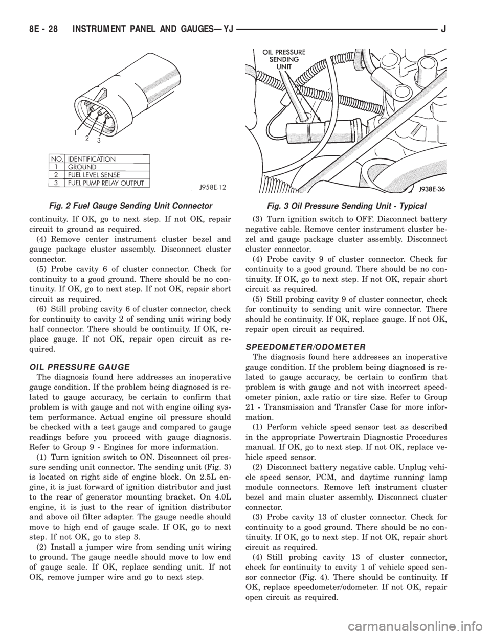
continuity. If OK, go to next step. If not OK, repair
circuit to ground as required.
(4) Remove center instrument cluster bezel and
gauge package cluster assembly. Disconnect cluster
connector.
(5) Probe cavity 6 of cluster connector. Check for
continuity to a good ground. There should be no con-
tinuity. If OK, go to next step. If not OK, repair short
circuit as required.
(6) Still probing cavity 6 of cluster connector, check
for continuity to cavity 2 of sending unit wiring body
half connector. There should be continuity. If OK, re-
place gauge. If not OK, repair open circuit as re-
quired.
OIL PRESSURE GAUGE
The diagnosis found here addresses an inoperative
gauge condition. If the problem being diagnosed is re-
lated to gauge accuracy, be certain to confirm that
problem is with gauge and not with engine oiling sys-
tem performance. Actual engine oil pressure should
be checked with a test gauge and compared to gauge
readings before you proceed with gauge diagnosis.
Refer to Group 9 - Engines for more information.
(1) Turn ignition switch to ON. Disconnect oil pres-
sure sending unit connector. The sending unit (Fig. 3)
is located on right side of engine block. On 2.5L en-
gine, it is just forward of ignition distributor and just
to the rear of generator mounting bracket. On 4.0L
engine, it is just to the rear of ignition distributor
and above oil filter adapter. The gauge needle should
move to high end of gauge scale. If OK, go to next
step. If not OK, go to step 3.
(2) Install a jumper wire from sending unit wiring
to ground. The gauge needle should move to low end
of gauge scale. If OK, replace sending unit. If not
OK, remove jumper wire and go to next step.(3) Turn ignition switch to OFF. Disconnect battery
negative cable. Remove center instrument cluster be-
zel and gauge package cluster assembly. Disconnect
cluster connector.
(4) Probe cavity 9 of cluster connector. Check for
continuity to a good ground. There should be no con-
tinuity. If OK, go to next step. If not OK, repair short
circuit as required.
(5) Still probing cavity 9 of cluster connector, check
for continuity to sending unit wire connector. There
should be continuity. If OK, replace gauge. If not OK,
repair open circuit as required.
SPEEDOMETER/ODOMETER
The diagnosis found here addresses an inoperative
gauge condition. If the problem being diagnosed is re-
lated to gauge accuracy, be certain to confirm that
problem is with gauge and not with incorrect speed-
ometer pinion, axle ratio or tire size. Refer to Group
21 - Transmission and Transfer Case for more infor-
mation.
(1) Perform vehicle speed sensor test as described
in the appropriate Powertrain Diagnostic Procedures
manual. If OK, go to next step. If not OK, replace ve-
hicle speed sensor.
(2) Disconnect battery negative cable. Unplug vehi-
cle speed sensor, PCM, and daytime running lamp
module connectors. Remove left instrument cluster
bezel and main cluster assembly. Disconnect cluster
connector.
(3) Probe cavity 13 of cluster connector. Check for
continuity to a good ground. There should be no con-
tinuity. If OK, go to next step. If not OK, repair short
circuit as required.
(4) Still probing cavity 13 of cluster connector,
check for continuity to cavity 1 of vehicle speed sen-
sor connector (Fig. 4). There should be continuity. If
OK, replace speedometer/odometer. If not OK, repair
open circuit as required.
Fig. 2 Fuel Gauge Sending Unit ConnectorFig. 3 Oil Pressure Sending Unit - Typical
8E - 28 INSTRUMENT PANEL AND GAUGESÐYJJ
Page 377 of 2198
TURN SIGNAL INDICATOR LAMPS
(1) Disconnect battery negative cable. Remove left
instrument cluster bezel and main cluster assembly.
Probe cavity 20 of cluster connector. Check for conti-
nuity to a good ground. There should be continuity. If
OK, go to next step. If not OK, repair open circuit to
ground.
(2) Connect battery negative cable. Install a
jumper wire from cavity 18 (left indicator) or cavity 7
(right indicator) of cluster connector to a 12-volt bat-
tery feed. Lamp should light. If OK, continue to next
step. If not OK, replace bulb.
(3) Disconnect battery negative cable. Check for
continuity between cavity 18 (left indicator) or cavity
7 (right indicator) of cluster connector and cavity H
(left front turn signal) or cavity J (right front turn
signal) of steering column wiring connector. There
should be continuity. If OK, refer to Group 8J - Turn
Signal and Hazard Warning Systems for further di-
agnosis. If not OK, repair open circuit as required.
UPSHIFT INDICATOR LAMP
(1) Disconnect battery negative cable. Unplug PCM
connector. Connect battery negative cable. Turn igni-
tion switch to ON. Install a jumper wire from cavity
54 of PCM connector (Fig. 5) to a good ground. Lamp
should light. Remove jumper from ground. Lamp
should go off. If OK, refer to Powertrain Diagnostic
Procedures manual to diagnose PCM. If not OK, turn
ignition switch to OFF and go to next step.
(2) Disconnect battery negative cable. Remove left
instrument cluster bezel and main cluster assembly.
Install a jumper wire from cavity 5 of cluster connec-
tor to a good ground. Connect battery negative cable.
Turn ignition switch to ON. Lamp should light. If
OK, go to next step. If not OK, replace bulb.
(3) Turn ignition switch to OFF. Disconnect battery
negative cable. Unplug cluster connector. Check for
continuity between cavity 5 of cluster connector and
a good ground. There should be no continuity. If OK,
go to next step. If not OK, repair short circuit as re-
quired.(4) Check for continuity between cavity 5 of cluster
connector and cavity 54 of PCM connector. There
should be continuity. If not OK, repair open circuit as
required.
CLUSTER ILLUMINATION LAMPS
(1) Check fuse 10 in fuseblock module. If OK, go to
next step. If not OK, replace fuse.
(2) Turn park lamps on at headlamp switch. Rotate
panel dimmer switch thumb-wheel to HI position,
just before interior lamps detent. Check for battery
voltage at fuse 10 in fuseblock module. Rotate panel
dimmer thumb-wheel towards LO position while ob-
serving test voltmeter. Reading should go from bat-
tery voltage to zero volts. If OK, go to next step. If
not OK, repair open circuit to headlamp switch or re-
fer to Group 8L - Lamps to diagnose headlamp
switch.
(3) Disconnect battery negative cable. Remove left
or center instrument cluster bezel and main or gauge
package cluster assembly. Unplug cluster connector.
Connect battery negative cable. Turn park lamps on
at headlamp switch. Rotate panel dimmer thumb-
wheel to HI position, just before interior lamps de-
tent. Check for battery voltage at cavity 21 of main
cluster connector, or cavity 7 of gauge package clus-
ter connector. If OK, go to next step. If not OK, re-
pair open circuit to fuse as required.
(4) Turn park lamps off. Disconnect battery nega-
tive cable. Remove fuse 10 from fuseblock module.
Probe cavity 21 of main cluster connector, or cavity 7
of gauge package cluster connector. Check for conti-
nuity to a good ground. There should be no continu-
ity. If OK, go to next step. If not OK, repair short
circuit as required.
(5) Probe cavity 20 of main cluster connector, or
cavities 1 and 13 of gauge package cluster connector.
Check for continuity to ground. There should be con-
tinuity. If not OK, repair open circuit as required.
8E - 34 INSTRUMENT PANEL AND GAUGESÐYJJ
Page 389 of 2198
ANTENNA
All models use a fixed-length stainless steel rod-
type antenna mast, installed at the right front (fend-
er on XJ, cowl side on YJ) of the vehicle. The
antenna mast is connected to the center wire of the
coaxial antenna cable and is not grounded to any
part of the vehicle.
To eliminate static, the antenna base must have a
good ground. The coaxial antenna cable shield (the
outer wire mesh of the cable) is grounded to the an-
tenna base and the radio chassis.
The factory installed ETRs automatically compen-
sate for radio antenna trim. Therefore, no antenna
trimmer adjustment is required or possible when re-
placing the receiver or the antenna.
RADIO NOISE SUPPRESSION
Radio Frequency Interference (RFI) and Electro-
Magnetic Interference (EMI) noise suppression is ac-
complished primarily through circuitry internal to
the radio receivers. These internal suppression de-
vices are only serviced as a part of the radio receiver.External suppression devices that are serviceable
and should be checked in the case of RFI or EMI
noise complaints include the following:
²radio antenna base ground
²engine-to-body ground strap
²resistor-type spark plugs
²radio suppression-type secondary ignition wiring.
In addition, if the source of RFI or EMI noise is
identified as a component on the vehicle (i.e.:genera-
tor, blower motor, etc.), the ground path for that com-
ponent should be checked. If excessive resistance is
found in that circuit, repair as required before con-
sidering any component replacement.
Fleet vehicles are available with an extra-cost RFI-
suppressed Powertrain Control Module (PCM). This
unit reduces interference generated by the PCM on
some radio frequencies used in two-way radio com-
munications. However, this unit will not resolve com-
plaints of RFI in the commercial AM or FM radio
frequency ranges.
DIAGNOSIS
RADIO
CAUTION: Do not operate the radio with speaker
leads detached since damage to the transistors
may result.
(1) Check fuse 2 in fuseblock module and fuse in
back of radio chassis. If OK, go to next step. If not
OK, replace fuse.
(2) Turn ignition switch to ON position. Check for
battery voltage at fuse 2. If OK, go to next step. If
not OK, repair circuit to ignition switch as required.
(3) Turn ignition switch to OFF position. Discon-
nect battery negative cable. Remove instrument clus-
ter bezel. Remove radio, but do not unplug any
connections. Check for continuity between the radio
chassis and a good ground. There should be continu-
ity. If OK, go to next step. If not OK, repair radio
ground circuit as required.
(4) Connect battery negative cable. Turn ignition
switch to ON position. See Radio Connections chart.
Check for battery voltage at cavity 3 of radio connec-
tor. If OK, go to next step. If not OK, repair circuit to
fuse 2 as required.
(5) Turn ignition switch to OFF position. Check for
battery voltage at cavity 4 of radio connector. If OK,
replace radio. If not OK, repair circuit to IOD fuse in
PDC as required.
SPEAKERS
CAUTION: Do not operate the radio with speaker
leads detached since damage to the transistors
may result.
(1) Turn radio on and adjust balance and fader
controls to check performance of each individual
speaker. Note the speaker locations that are not per-
forming correctly. Go to next step.
(2) Turn radio off. Disconnect battery negative ca-
ble. Remove instrument cluster bezel and remove ra-
dio. See Radio Connections chart. Check both the
speaker feed and return cavities at radio for continu-
ity to a good ground. There should be no continuity.
If OK, go to next step. If not OK, repair wiring cir-
cuit as required.
(3) Check resistance between speaker feed and re-
turn cavities. Meter should read between 3 and 8
ohms (speaker impedance). If OK, see diagnosis for
Radio. If not OK, go to next step.
(4) Unplug speaker wiring connector. Check for
continuity between speaker feed cavity at radio and
at speaker. Repeat check between speaker return
cavity at radio and at speaker. If OK, replace
speaker. If not OK, repair wiring circuit as required.
8F - 2 AUDIO SYSTEMSJ
Page 404 of 2198
VEHICLE SPEED CONTROL SYSTEM
CONTENTS
page page
DIAGNOSIS............................. 2
GENERAL INFORMATION.................. 1SERVICE PROCEDURES................... 9
GENERAL INFORMATION
The vehicle speed control system (Fig. 1) is an
available option on all XJ (Cherokee) models. The
system is electronically controlled and vacuum oper-
ated. Following are general descriptions of the major
components in the vehicle speed control system. Re-
fer to Group 8W - Wiring Diagrams for complete cir-
cuit descriptions and diagrams.
SPEED CONTROL SERVO
The speed control servo is mounted to a bracket on
the right side inner fender shield in the engine com-
partment. The servo unit consists of a solenoid valve
body, a vacuum servo and the mounting bracket. The
PCM controls the solenoid valve body. The solenoid
valve body controls the application and release of
vacuum to the diaphragm of the vacuum servo. The
servo unit cannot be repaired and is serviced only as
a complete assembly.
SPEED CONTROL SWITCH
The speed control switch module is mounted to the
center of the steering wheel below the driver's airbag
module. The PCM monitors the state of the speed
control switches. The individual switches are labeled:
OFF/ON, RESUME/ACCEL, SET/COAST. Refer to
the owner's manual for more information on speed
control switch functions and setting procedures. The
individual switches cannot be repaired. If one switch
fails, the entire switch module must be replaced.
STOP LAMP SWITCH
Vehicles with the speed control option use a dual
function stop lamp switch. The switch is mounted in
the same location as the conventional stop lamp
switch, on the brake pedal mounting bracket under
the instrument panel. The PCM monitors the state of
the dual function stop lamp switch. Refer to Group 5
- Brakes for more information on stop lamp switch
service and adjustment procedures.
SERVO CABLE
The speed control servo cable is connected betweenthe speed control vacuum servo diaphragm and the
throttle control linkage. This cable causes the throt-
tle control linkage to open or close the throttle valve
in response to movement of the vacuum servo dia-
phragm.
POWERTRAIN CONTROL MODULE
The speed control electronic control circuitry is in-
tegrated into the Powertrain Control Module (PCM).
The PCM is located in the engine compartment on
the left side inner fender shield. The PCM speed con-
trol functions are monitored by the On-Board Diag-
nostics (OBD). All OBD-sensed systems are
monitored by the PCM. Each monitored circuit is as-
signed a Diagnostic Trouble Code (DTC). The PCM
will store a DTC in electronic memory for any failure
it detects. See Using On-Board Diagnostic System in
this group for more information. The PCM cannot be
repaired and must be replaced if faulty.
VACUUM RESERVOIR
The vacuum reservoir is mounted behind the left
end of the front bumper bar. The reservoir contains a
one-way check valve to trap engine vacuum in the
reservoir. When engine vacuum drops, as in climbing
a grade while driving, the reservoir supplies the vac-
uum needed to maintain proper speed control opera-
tion. The vacuum reservoir cannot be repaired and
must be replaced if faulty.
VEHICLE SPEED SENSOR
The Vehicle Speed Sensor (VSS) is a pulse genera-
tor mounted to an adapter near the transmission
(two-wheel drive) or transfer case (four-wheel drive)
output shaft. The sensor is driven through the
adapter by a speedometer pinion gear. The VSS pulse
signal to the speedometer/odometer is monitored by
the PCM speed control circuitry to determine vehicle
speed and to maintain speed control set speed. Refer
to the appropriate Powertrain Diagnostic Procedures
manual for testing of this component. Refer to Group
14 - Fuel System for service of this component.
JVEHICLE SPEED CONTROL SYSTEM 8H - 1
Page 780 of 2198
CONNECTOR LOCATIONS
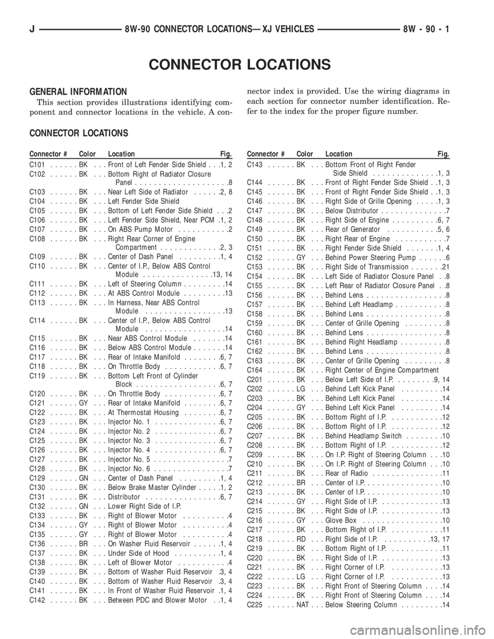
GENERAL INFORMATION
This section provides illustrations identifying com-
ponent and connector locations in the vehicle. A con-nector index is provided. Use the wiring diagrams in
each section for connector number identification. Re-
fer to the index for the proper figure number.
CONNECTOR LOCATIONS
Connector # Color Location Fig.
C101......BK ...Front of Left Fender Side Shield . . .1, 2
C102......BK ...Bottom Right of Radiator Closure
Panel....................8
C103......BK ...Near Left Side of Radiator......2,8
C104......BK ...Left Fender Side Shield
C105......BK ...Bottom of Left Fender Side Shield . . .2
C106......BK ...Left Fender Side Shield, Near PCM .1, 2
C107......BK ...OnABSPump Motor...........2
C108......BK ...Right Rear Corner of Engine
Compartment.............2,3
C109......BK ...Center of Dash Panel.........1,4
C110......BK ...Center of I.P., Below ABS Control
Module...............13, 14
C111......BK ...Left of Steering Column.........14
C112......BK ...AtABSControl Module.........13
C113......BK ...InHarness, Near ABS Control
Module.................13
C114......BK ...Center of I.P., Below ABS Control
Module.................14
C115......BK ...Near ABS Control Module.......14
C116......BK ...Below ABS Control Module.......14
C117......BK ...Rear of Intake Manifold........6,7
C118......BK ...OnThrottle Body............6,7
C119......BK ...Bottom Left Front of Cylinder
Block..................6,7
C120......BK ...OnThrottle Body............6,7
C121......GY ...Rear of Intake Manifold........6,7
C122......BK ...AtThermostat Housing........6,7
C123......BK ...Injector No. 1..............6,7
C124......BK ...Injector No. 2..............6,7
C125......BK ...Injector No. 3..............6,7
C126......BK ...Injector No. 4..............6,7
C127......BK ...Injector No. 5................7
C128......BK ...Injector No. 6................7
C129......GN ...Center of Dash Panel.........1,4
C130......BK ...Below Brake Master Cylinder.....1,2
C131......BK ...Distributor................6,7
C132......GN ...Lower Right Side of I.P.
C133......BK ...Right of Blower Motor..........4
C134......GY ...Right of Blower Motor..........4
C135......GY ...Right of Blower Motor..........4
C136......BR ...OnWasher Fluid Reservoir......1,4
C137......BK ...Under Side of Hood..........1,4
C138......BK ...Left of Blower Motor...........4
C139......BK ...Bottom of Washer Fluid Reservoir .3, 4
C140......BK ...Bottom of Washer Fluid Reservoir .3, 4
C141......BK ...InFront of Washer Fluid Reservoir .1, 4
C142......BK ...Between PDC and Blower Motor . .1, 4Connector # Color Location Fig.
C143......BK ...Bottom Front of Right Fender
Side Shield..............1,3
C144......BK ...Front of Right Fender Side Shield . .1, 3
C145......BK ...Front of Right Fender Side Shield . .1, 3
C146......BK ...Right Side of Grille Opening.....1,3
C147......BK ...Below Distributor..............7
C148......BK ...Right Side of Engine..........6,7
C149......BK ...Rear of Generator...........5,6
C150......BK ...Right Rear of Engine...........7
C151......BK ...Right Fender Side Shield.......1,4
C152......GY ...Behind Power Steering Pump......6
C153......BK ...Right Side of Transmission.......21
C154......BK ...Left Side of Radiator Closure Panel . .8
C155......BK ...Left Rear of Radiator Closure Panel . .8
C156......BK ...Behind Lens.................8
C157......BK ...Behind Left Headlamp...........8
C158......BK ...Behind Lens.................8
C159......BK ...Center of Grille Opening.........8
C160......BK ...Behind Lens.................8
C161......BK ...Behind Right Headlamp..........8
C162......BK ...Behind Lens.................8
C163......BK ...Center of Grille Opening.........8
C164......BK ...Right Center of Engine Compartment
C201......BK ...Below Left Side of I.P.........9,14
C202......LG ...Behind Left Kick Panel.........14
C203......BK ...Behind Left Kick Panel.........14
C204......GY ...Behind Left Kick Panel.........14
C205......BK ...Bottom Right of I.P............12
C206......BK ...Bottom Right of I.P............12
C207......BK ...Behind Headlamp Switch........10
C208......BK ...Bottom Right of I.P............12
C209......BK ...OnI.P.Right of Steering Column . . .10
C210......BK ...OnI.P.Right of Steering Column . . .10
C211......BK ...Rear of Radio...............11
C212......BR ...Center of I.P.................10
C213......BK ...Center of I.P.................10
C214......GY ...Right Side of I.P..............13
C215......BK ...Right Side of I.P..............13
C216......GY ...Glove Box.................10
C217......BK ...Bottom Right of I.P............11
C218......RD ...Right Side of I.P...........13, 17
C219......BK ...Bottom Right of I.P............11
C220......BK ...Right Side of I.P..............13
C221......BK ...Right Corner of I.P............13
C222......LG ...Right Corner of I.P............13
C223......BK ...Right Front of Steering Column....14
C224......BK ...Right Front of Steering Column....14
C225......NAT...Below Steering Column.........14
J8W-90 CONNECTOR LOCATIONSÐXJ VEHICLES 8W - 90 - 1
Page 1238 of 2198
The engine will not operate if the PCM does not re-
ceive a crankshaft position sensor input.
ENGINE COOLANT TEMPERATURE SENSORÐPCM
INPUT
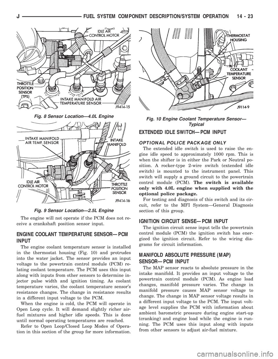
The engine coolant temperature sensor is installed
in the thermostat housing (Fig. 10) and protrudes
into the water jacket. The sensor provides an input
voltage to the powertrain control module (PCM) re-
lating coolant temperature. The PCM uses this input
along with inputs from other sensors to determine in-
jector pulse width and ignition timing. As coolant
temperature varies, the coolant temperature sensor's
resistance changes. The change in resistance results
in a different input voltage to the PCM.
When the engine is cold, the PCM will operate in
Open Loop cycle. It will demand slightly richer air-
fuel mixtures and higher idle speeds. This is done
until normal operating temperatures are reached.
Refer to Open Loop/Closed Loop Modes of Opera-
tion in this section of the group for more information.
EXTENDED IDLE SWITCHÐPCM INPUT
OPTIONAL POLICE PACKAGE ONLY
The extended idle switch is used to raise the en-
gine idle speed to approximately 1000 rpm. This is
when the shifter is in either the Park or Neutral po-
sition. A rocker-type 2-wire switch (extended idle
switch) is mounted to the instrument panel. This
switch will supply a ground circuit to the powertrain
control module (PCM).The switch is available
only with 4.0L engine when supplied with the
optional police package.
For testing and diagnosis of this switch and its cir-
cuit, refer to the MFI SystemÐGeneral Diagnosis
section of this group.
IGNITION CIRCUIT SENSEÐPCM INPUT
The ignition circuit sense input tells the powertrain
control module (PCM) the ignition switch has ener-
gized the ignition circuit. Refer to the wiring dia-
grams for circuit information.
MANIFOLD ABSOLUTE PRESSURE (MAP)
SENSORÐPCM INPUT
The MAP sensor reacts to absolute pressure in the
intake manifold. It provides an input voltage to the
powertrain control module (PCM). As engine load
changes, manifold pressure varies. The change in
manifold pressure causes MAP sensor voltage to
change. The change in MAP sensor voltage results in
a different input voltage to the PCM. The input volt-
age level supplies the PCM with information about
ambient barometric pressure during engine start-up
(cranking) and engine load while the engine is run-
ning. The PCM uses this input along with inputs
from other sensors to adjust air-fuel mixture.
Fig. 8 Sensor LocationÐ4.0L Engine
Fig. 9 Sensor LocationÐ2.5L Engine
Fig. 10 Engine Coolant Temperature SensorÐ
Typical
JFUEL SYSTEM COMPONENT DESCRIPTION/SYSTEM OPERATION 14 - 23
Page 1242 of 2198
DATA LINK CONNECTORÐPCM OUTPUT
Refer to the previous paragraphs on Data Link
ConnectorÐPCM Input for information.
EMR LAMPÐPCM OUTPUT
The EMR (SRI) lamp is not used for the 1995
model year.
FUEL PUMP RELAYÐPCM OUTPUT
The PCM energizes the fuel pump and the oxygen
sensor (O2S) heating element through the fuel pump
relay. Battery voltage is applied to the relay from the
ignition switch. The relay is energized when a
ground is provided by the PCM. Refer to Automatic
Shutdown Relay for additional information.
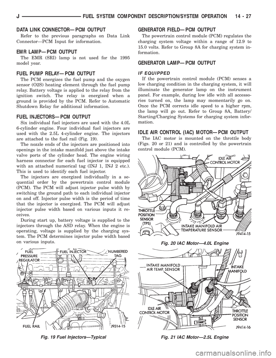
FUEL INJECTORSÐPCM OUTPUT
Six individual fuel injectors are used with the 4.0L
6-cylinder engine. Four individual fuel injectors are
used with the 2.5L 4-cylinder engine. The injectors
are attached to the fuel rail (Fig. 19).
The nozzle ends of the injectors are positioned into
openings in the intake manifold just above the intake
valve ports of the cylinder head. The engine wiring
harness connector for each fuel injector is equipped
with an attached numerical tag (INJ 1, INJ 2 etc.).
This is used to identify each fuel injector.
The injectors are energized individually in a se-
quential order by the powertrain control module
(PCM). The PCM will adjust injector pulse width by
switching the ground path to each individual injector
on and off. Injector pulse width is the period of time
that the injector is energized. The PCM will adjust
injector pulse width based on various inputs it re-
ceives.
During start up, battery voltage is supplied to the
injectors through the ASD relay. When the engine is
operating, voltage is supplied by the charging sys-
tem. The PCM determines injector pulse width based
on various inputs.
GENERATOR FIELDÐPCM OUTPUT
The powertrain control module (PCM) regulates the
charging system voltage within a range of 12.9 to
15.0 volts. Refer to Group 8A for charging system in-
formation.
GENERATOR LAMPÐPCM OUTPUT
IF EQUIPPED
If the powertrain control module (PCM) senses a
low charging condition in the charging system, it will
illuminate the generator lamp on the instrument
panel. For example, during low idle with all accesso-
ries turned on, the lamp may momentarily go on.
Once the PCM corrects idle speed to a higher rpm,
the lamp will go out. Refer to Group 8A, Battery/
Starting/Charging Systems for charging system infor-
mation.
IDLE AIR CONTROL (IAC) MOTORÐPCM OUTPUT
The IAC motor is mounted on the throttle body
(Figs. 20 or 21) and is controlled by the powertrain
control module (PCM).
Fig. 19 Fuel InjectorsÐTypical
Fig. 20 IAC MotorÐ4.0L Engine
Fig. 21 IAC MotorÐ2.5L Engine
JFUEL SYSTEM COMPONENT DESCRIPTION/SYSTEM OPERATION 14 - 27
Page 1255 of 2198
plugged catalytic convertor.
(27) If equipped with automatic transmission, ver-
ify that electrical harness is firmly connected to park/
neutral safety switch. Refer to Automatic
Transmission section of Group 21.
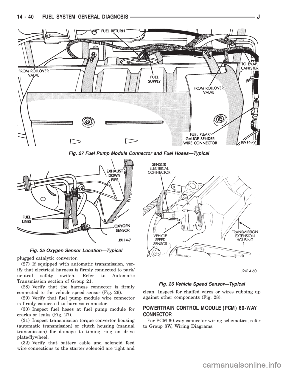
(28) Verify that the harness connector is firmly
connected to the vehicle speed sensor (Fig. 26).
(29) Verify that fuel pump module wire connector
is firmly connected to harness connector.
(30) Inspect fuel hoses at fuel pump module for
cracks or leaks (Fig. 27).
(31) Inspect transmission torque convertor housing
(automatic transmission) or clutch housing (manual
transmission) for damage to timing ring on drive
plate/flywheel.
(32) Verify that battery cable and solenoid feed
wire connections to the starter solenoid are tight andclean. Inspect for chaffed wires or wires rubbing up
against other components (Fig. 28).
POWERTRAIN CONTROL MODULE (PCM) 60-WAY
CONNECTOR
For PCM 60-way connector wiring schematics, refer
to Group 8W, Wiring Diagrams.
Fig. 27 Fuel Pump Module Connector and Fuel HosesÐTypical
Fig. 25 Oxygen Sensor LocationÐTypical
Fig. 26 Vehicle Speed SensorÐTypical
14 - 40 FUEL SYSTEM GENERAL DIAGNOSISJ