1995 JEEP CHEROKEE electrical wiring
[x] Cancel search: electrical wiringPage 66 of 2198
SHIFT MOTORÐREMOVAL/DISASSEMBLY
(1) Disconnect the vacuum and wiring connector
from the shift housing.
(2) Remove indicator switch.
(3) Remove the shift motor housing cover, gasket
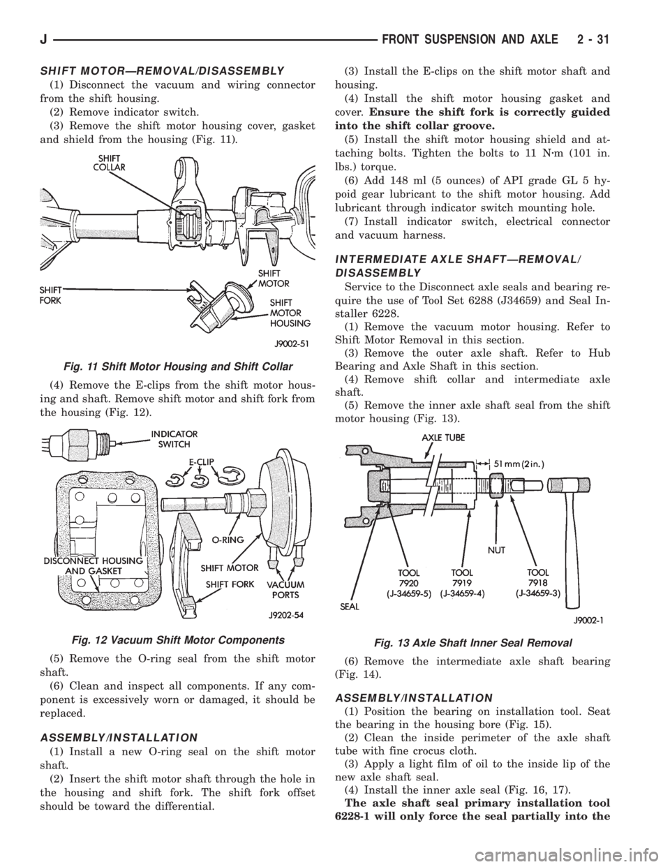
and shield from the housing (Fig. 11).
(4) Remove the E-clips from the shift motor hous-
ing and shaft. Remove shift motor and shift fork from
the housing (Fig. 12).
(5) Remove the O-ring seal from the shift motor
shaft.
(6) Clean and inspect all components. If any com-
ponent is excessively worn or damaged, it should be
replaced.
ASSEMBLY/INSTALLATION
(1) Install a new O-ring seal on the shift motor
shaft.
(2) Insert the shift motor shaft through the hole in
the housing and shift fork. The shift fork offset
should be toward the differential.(3) Install the E-clips on the shift motor shaft and
housing.
(4) Install the shift motor housing gasket and
cover.Ensure the shift fork is correctly guided
into the shift collar groove.
(5) Install the shift motor housing shield and at-
taching bolts. Tighten the bolts to 11 Nzm (101 in.
lbs.) torque.
(6) Add 148 ml (5 ounces) of API grade GL 5 hy-
poid gear lubricant to the shift motor housing. Add
lubricant through indicator switch mounting hole.
(7) Install indicator switch, electrical connector
and vacuum harness.
INTERMEDIATE AXLE SHAFTÐREMOVAL/
DISASSEMBLY
Service to the Disconnect axle seals and bearing re-
quire the use of Tool Set 6288 (J34659) and Seal In-
staller 6228.
(1) Remove the vacuum motor housing. Refer to
Shift Motor Removal in this section.
(3) Remove the outer axle shaft. Refer to Hub
Bearing and Axle Shaft in this section.
(4) Remove shift collar and intermediate axle
shaft.
(5) Remove the inner axle shaft seal from the shift
motor housing (Fig. 13).
(6) Remove the intermediate axle shaft bearing
(Fig. 14).
ASSEMBLY/INSTALLATION
(1) Position the bearing on installation tool. Seat
the bearing in the housing bore (Fig. 15).
(2) Clean the inside perimeter of the axle shaft
tube with fine crocus cloth.
(3) Apply a light film of oil to the inside lip of the
new axle shaft seal.
(4) Install the inner axle seal (Fig. 16, 17).
The axle shaft seal primary installation tool
6228-1 will only force the seal partially into the
Fig. 11 Shift Motor Housing and Shift Collar
Fig. 12 Vacuum Shift Motor ComponentsFig. 13 Axle Shaft Inner Seal Removal
JFRONT SUSPENSION AND AXLE 2 - 31
Page 254 of 2198
(4) For access to radiator draincock, remove radia-
tor grille mounting screws and remove grill. Refer to
Group 23, Body for procedures.
(5) Attach one end of a 24 inch long X 1/4 inch ID
hose to the radiator draincock. Put the other end into
a clean container. Open draincock and drain radiator.
(6) If equipped, disconnect auxiliary electric cooling
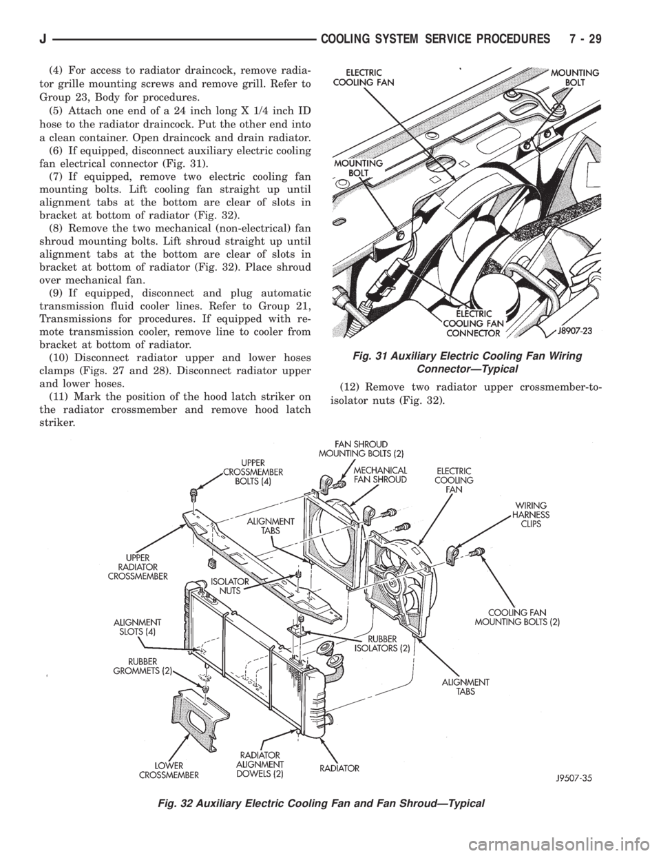
fan electrical connector (Fig. 31).
(7) If equipped, remove two electric cooling fan
mounting bolts. Lift cooling fan straight up until
alignment tabs at the bottom are clear of slots in
bracket at bottom of radiator (Fig. 32).
(8) Remove the two mechanical (non-electrical) fan
shroud mounting bolts. Lift shroud straight up until
alignment tabs at the bottom are clear of slots in
bracket at bottom of radiator (Fig. 32). Place shroud
over mechanical fan.
(9) If equipped, disconnect and plug automatic
transmission fluid cooler lines. Refer to Group 21,
Transmissions for procedures. If equipped with re-
mote transmission cooler, remove line to cooler from
bracket at bottom of radiator.
(10) Disconnect radiator upper and lower hoses
clamps (Figs. 27 and 28). Disconnect radiator upper
and lower hoses.
(11) Mark the position of the hood latch striker on
the radiator crossmember and remove hood latch
striker.(12) Remove two radiator upper crossmember-to-
isolator nuts (Fig. 32).
Fig. 31 Auxiliary Electric Cooling Fan Wiring
ConnectorÐTypical
Fig. 32 Auxiliary Electric Cooling Fan and Fan ShroudÐTypical
JCOOLING SYSTEM SERVICE PROCEDURES 7 - 29
Page 272 of 2198
ELECTRICAL
GROUP INDEX
Group Group
AUDIO SYSTEMS........................ 8F
BATTERY/STARTER/GENERATOR SERVICE.... 8B
BATTERY/STARTING/CHARGING SYSTEMS
DIAGNOSTICS......................... 8A
CHIME/BUZZER WARNING SYSTEMS........ 8U
HORNS................................ 8G
IGNITION SYSTEMS...................... 8D
INSTRUMENT PANEL AND GAUGES......... 8E
LAMPS................................ 8L
OVERHEAD CONSOLE.................... 8C
POWER LOCKS.......................... 8P
POWER MIRRORS....................... 8TPOWER SEATS.......................... 8R
POWER WINDOWS....................... 8S
REAR WINDOW DEFOGGER............... 8N
RESTRAINT SYSTEMS................... 8M
TURN SIGNAL AND HAZARD WARNING
SYSTEMS............................. 8J
VEHICLE SPEED CONTROL SYSTEM......... 8H
WIPER AND WASHER SYSTEMS............ 8K
XJ WIRING DIAGRAMS-LEFT HAND DRIVE . . . 8W
XJ WIRING DIAGRAMS-RIGHT HAND DRIVE . 8W
YJ WIRING DIAGRAMS.................. 8W
BATTERY/STARTING/CHARGING SYSTEMS DIAGNOSTICS
CONTENTS
page page
BATTERY............................... 2
CHARGING SYSTEM..................... 17
IGNITION-OFF DRAW.................... 10SPECIFICATIONS........................ 23
STARTING SYSTEM...................... 11
USING ON-BOARD DIAGNOSTIC SYSTEM.... 22
GENERAL INFORMATION
The battery, starting, and charging systems operate
with one another; therefore, they must be tested as a
complete system. In order for the vehicle to start and
charge properly, all of the components involved in
these systems must perform within specifications.
Group 8A covers battery, starting (Fig. 1) and
charging (Fig. 2) system diagnostic procedures. These
procedures include the most basic conventional diag-
nostic methods, to On-Board Diagnostics (OBD) builtinto the Powertrain Control Module (PCM). Use of an
induction milliamp ammeter, volt/ohmmeter, battery
charger, carbon pile rheostat (load tester), and 12-
volt test lamp will be required.
All OBD-sensed systems are monitored by the
PCM. Each monitored circuit is assigned a Diagnos-
tic Trouble Code (DTC). The PCM will store a DTC in
electronic memory for any failure it detects. See Us-
ing On-Board Diagnostic System in this group for
more information.
JELECTRICAL 8A - 1
Page 281 of 2198
IGNITION-OFF DRAW
GENERAL INFORMATION
Ignition-Off Draw (IOD) refers to power being
drained from the battery with the ignition switch
turned OFF. A normal vehicle electrical system will
draw from 5 to 20 milliamps (0.005 - 0.020 amps).
This is with the ignition switch in the OFF position,
and all non-ignition controlled circuits in proper
working order. The 20 milliamps are needed to sup-
ply PCM memory, digital clock memory, and electron-
ically-tuned radio memory.
A vehicle that has not been operated for approxi-
mately 20 days, may discharge the battery to an in-
adequate level. When a vehicle will not be used for
20 days or more (stored), remove the IOD fuse in the
Power Distribution Center (PDC). This will reduce
battery discharging.
Excessive battery drain can be caused by:
²electrical items left on
²faulty or improperly adjusted switches
²internally shorted generator
²intermittent shorts in the wiring.
If the IOD is over 20 milliamps, the problem must
be found and corrected before replacing a battery. In
most cases, the battery can be charged and returned
to service.
DIAGNOSIS
Testing for high-amperage IOD must be per-
formed first to prevent damage to most milli-
amp meters.
(1) Verify that all electrical accessories are off.
Turn off all lamps, remove ignition key, and close all
doors. If the vehicle is equipped with illuminated en-
try or electronically-tuned radio, allow the systems to
automatically shut off (time out). This may take up
to 3 minutes.
(2) Determine that the underhood lamp is operat-
ing properly, then disconnect or remove bulb.
(3) Disconnect negative cable from battery.
(4) Connect a typical 12-volt test lamp (low-watt-
age bulb) between the negative cable clamp and the
battery negative terminal. Make sure that the doors
remain closed so that illuminated entry is not acti-
vated.The test lamp may light brightly for up to 3 min-
utes, or may not light at all, depending upon the ve-
hicle's electrical equipment. The term brightly, as
used throughout the following tests, implies the
brightness of the test lamp will be the same as if it
were connected across the battery.
The test lamp must be securely clamped to the neg-
ative cable clamp and battery negative terminal. If
the test lamp becomes disconnected during any part
of the IOD test, the electronic timer function will be
activated and all tests must be repeated.
(5) After 3 minutes the test lamp should turn off
or be dimly lit, depending upon the vehicle's electri-
cal equipment. If the test lamp remains brightly lit,
do not disconnect it. Remove each fuse or circuit
breaker (refer to Group 8W - Wiring Diagrams) until
test lamp is either off or dimly lit. This will isolate
each circuit and identify the source of the high-am-
perage draw.
If the test lamp is still brightly lit after disconnect-
ing each fuse and circuit breaker, disconnect the wir-
ing harness from the generator. If test lamp now
turns off or is dimly lit, see Charging System in this
group to diagnose faulty generator. Do not disconnect
the test lamp.
After high-amperage IOD has been corrected, low-
amperage IOD may be checked. It is now safe to in-
stall a milliamp meter to check for low- amperage
IOD.
(6) With test lamp still connected securely, clamp a
milliamp meter between battery negative terminal
and negative cable clamp.
Do not open any doors or turn on any electri-
cal accessories with the test lamp disconnected
or the milliamp meter may be damaged.
(7) Disconnect test lamp. Observe milliamp meter.
The current draw should not exceed 0.020 amp. If
draw exceeds 20 milliamps, isolate each circuit by re-
moving circuit breakers and fuses. The milliamp
meter reading will drop when the source of the draw
is disconnected. Repair this circuit as necessary,
whether a wiring short, incorrect switch adjustment
or a component failure is found.
8A - 10 BATTERY/STARTING/CHARGING SYSTEMS DIAGNOSTICSJ
Page 296 of 2198
BATTERY/STARTER/GENERATOR SERVICE
CONTENTS
page page
BATTERY............................... 1
GENERATOR............................ 6SPECIFICATIONS......................... 8
STARTER AND STARTER RELAY............. 4
GENERAL INFORMATION
Group 8B covers battery, starter and generator ser-
vice procedures. For diagnosis of these components
and their related systems, refer to Group 8A - Bat-tery/Starting/Charging Systems Diagnostics. Refer to
Group 8W - Wiring Diagrams for complete circuit de-
scriptions and diagrams.
BATTERY
GENERAL INFORMATION
This section covers battery service procedures only.
For battery maintenance procedures, refer to Group 0
- Lubrication and Maintenance. While battery charg-
ing can be considered a service or maintenance pro-
cedure, this information is located in Group 8A -
Battery/Starting/Charging Systems Diagnostics. This
was done because the battery must be fully charged
before any diagnosis is performed.
It is important that the battery, starting, and
charging systems be thoroughly tested and inspected
any time a battery needs to be charged or replaced.
The cause of abnormal discharge, over-charging, or
premature failure of the battery must be diagnosed
and corrected before a battery is replaced or returned
to service. Refer to Group 8A - Battery/Starting/
Charging Systems Diagnostics.
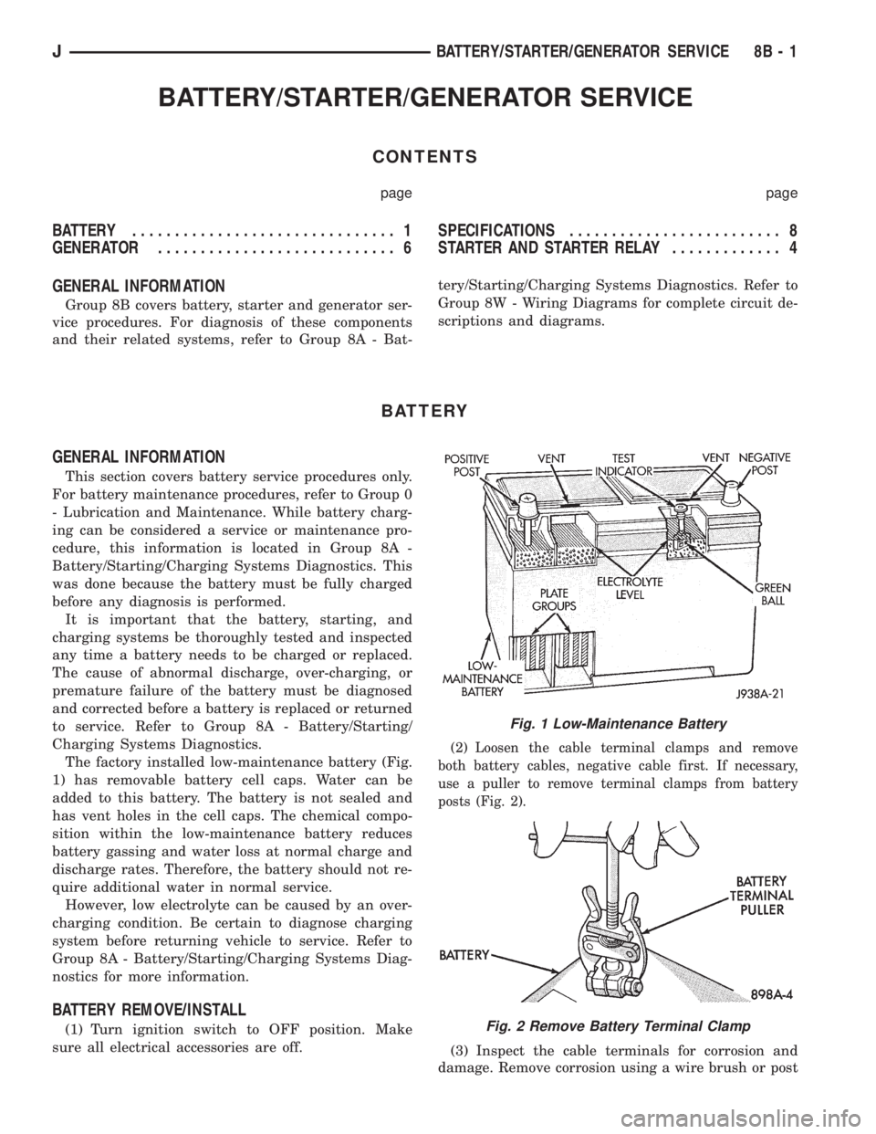
The factory installed low-maintenance battery (Fig.
1) has removable battery cell caps. Water can be
added to this battery. The battery is not sealed and
has vent holes in the cell caps. The chemical compo-
sition within the low-maintenance battery reduces
battery gassing and water loss at normal charge and
discharge rates. Therefore, the battery should not re-
quire additional water in normal service.
However, low electrolyte can be caused by an over-
charging condition. Be certain to diagnose charging
system before returning vehicle to service. Refer to
Group 8A - Battery/Starting/Charging Systems Diag-
nostics for more information.
BATTERY REMOVE/INSTALL
(1) Turn ignition switch to OFF position. Make
sure all electrical accessories are off.
(2) Loosen the cable terminal clamps and remove
both battery cables, negative cable first. If necessary,
use a puller to remove terminal clamps from battery
posts (Fig. 2).
(3) Inspect the cable terminals for corrosion and
damage. Remove corrosion using a wire brush or post
Fig. 1 Low-Maintenance Battery
Fig. 2 Remove Battery Terminal Clamp
JBATTERY/STARTER/GENERATOR SERVICE 8B - 1
Page 299 of 2198
CAUTION: Be certain that battery cables are con-
nected to the correct battery terminals. Reverse po-
larity can damage electrical components.
(12) Place oiled felt washer on battery positive ter-
minal post.
(13) Install and tighten battery positive cable ter-
minal clamp. Then install and tighten negative cableterminal clamp. Both cable clamp bolts require
torque of 8.5 Nzm (75 in. lbs.).
(14) Apply a thin coating of petroleum jelly or
chassis grease to cable terminals and battery posts.
STARTER AND STARTER RELAY
GENERAL INFORMATION
This section covers starter and starter relay service
procedures only. For diagnostic procedures, refer to
Group 8A - Battery/Starting/Charging Systems Diag-
nostics. Service procedures for other starting system
components can be found as follows:
²battery - see Battery, in this group
²ignition switch - refer to Group 8D - Ignition Sys-
tems
²park/neutral position switch (automatic transmis-
sion) - refer to Group 21 - Transmission and Transfer
Case
²wiring harness and connectors - refer to Group 8W
- Wiring Diagrams.
STARTER
The starter motor incorporates several features to
create a reliable, efficient, compact and lightweight
unit. A planetary gear system (intermediate trans-
mission) is used between the electric motor and pin-
ion gear. This feature makes it possible to reduce the
dimensions of the starter. At the same time, it allows
higher armature rotational speed and delivers in-
creased torque through the pinion gear to the fly-
wheel or drive plate ring gear.
The use of a permanent magnet field also reduces
starter size and weight. This field consists of six
high-strength permanent magnets. The magnets are
aligned according to their polarity and are perma-
nently fixed in the starter field frame.
The starter motors for all engines are activated by
a solenoid mounted to the overrunning clutch hous-
ing. However, the starter motor/solenoid are serviced
only as a complete assembly. If either component
fails, the entire assembly must be replaced.
This unit is highly sensitive to hammering, shocks
and external pressure.
CAUTION: The starter motor MUST NOT BE
CLAMPED in a vise by the starter field frame. Doing
so may damage the magnets. It may be clamped by
the mounting flange ONLY.CAUTION: Do not connect starter motor incorrectly
when tests are being performed. The permanent
magnets may be damaged and rendered unservice-
able.
STARTER RELAY
The starter relay is an International Standards Or-
ganization (ISO) type relay, and is located in the
Power Distribution Center (PDC). Refer to underside
of PDC cover for relay location.
STARTER REMOVE/INSTALLÐ2.5L
XJ MODELS
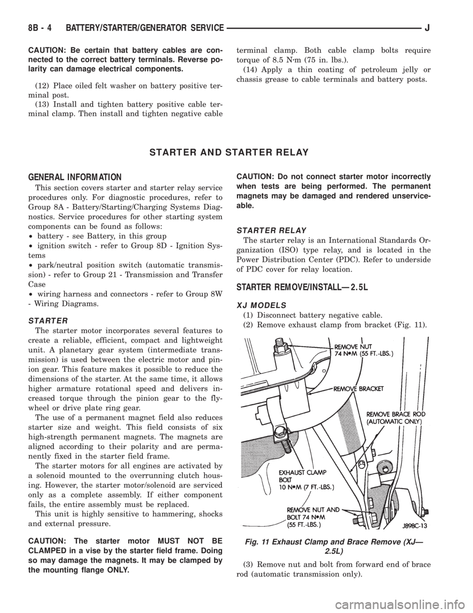
(1) Disconnect battery negative cable.
(2) Remove exhaust clamp from bracket (Fig. 11).
(3) Remove nut and bolt from forward end of brace
rod (automatic transmission only).
Fig. 11 Exhaust Clamp and Brace Remove (XJÐ
2.5L)
8B - 4 BATTERY/STARTER/GENERATOR SERVICEJ
Page 305 of 2198
DIAGNOSIS
COMPASS/DISPLAY SELF-DIAGNOSTIC TEST
This self-diagnostic test is used to determine that
the compass and all of its display segments are oper-
ating properly electrically. Initiate the self-diagnostic
test as follows:
(1) With the ignition switch in the OFF position,
simultaneously press and hold the COMP/TEMP but-
ton and the US/METRIC button.
(2) Turn ignition switch to the ON position.
(3) Continue to hold both buttons until the display
performs a walking segment test. In this test all of
the compass points are displayed, along with various
number combinations. These combinations verify that
all display segments are functional. If any segment
should fail to light during the test, the unit is faulty
and requires replacement. To repeat the test, momen-
tarily depress and release the COMP/TEMP button
one time.
(4) Momentarily depress and release the US/MET-
RIC button one time and all segments will light si-
multaneously for about 2 seconds. If any segment
should fail to light during the test, the unit is faulty
and requires replacement. To repeat the test, momen-
tarily depress and release the COMP/TEMP button
one time.
(5) Momentarily depress and release the US/MET-
RIC button one time or turn the ignition switch to
OFF to exit the self-diagnostic mode and return to
normal operation.
If the compass functions, but accuracy is sus-
pect, it may be necessary to perform a variation
adjustment. This procedure allows the unit to
accommodate variations in the earth's mag-
netic field strength based on geographic loca-
tion. See Compass Variation Adjustment, in this
group.
If the compass display has blanked out and
only CAL appears, demagnetizing may be nec-
essary to remove excessive residual magnetic
fields from the vehicle. See Compass Demagne-
tizing, in this group.
THERMOMETER DIAGNOSIS
The thermometer function is supported by a tem-
perature sensor, a wiring circuit and a portion of the
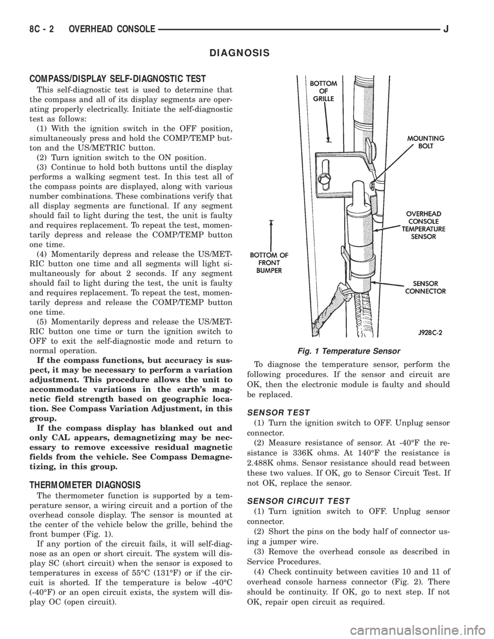
overhead console display. The sensor is mounted at
the center of the vehicle below the grille, behind the
front bumper (Fig. 1).
If any portion of the circuit fails, it will self-diag-
nose as an open or short circuit. The system will dis-
play SC (short circuit) when the sensor is exposed to
temperatures in excess of 55ÉC (131ÉF) or if the cir-
cuit is shorted. If the temperature is below -40ÉC
(-40ÉF) or an open circuit exists, the system will dis-
play OC (open circuit).To diagnose the temperature sensor, perform the
following procedures. If the sensor and circuit are
OK, then the electronic module is faulty and should
be replaced.
SENSOR TEST
(1) Turn the ignition switch to OFF. Unplug sensor
connector.
(2) Measure resistance of sensor. At -40ÉF the re-
sistance is 336K ohms. At 140ÉF the resistance is
2.488K ohms. Sensor resistance should read between
these two values. If OK, go to Sensor Circuit Test. If
not OK, replace the sensor.
SENSOR CIRCUIT TEST
(1) Turn ignition switch to OFF. Unplug sensor
connector.
(2) Short the pins on the body half of connector us-
ing a jumper wire.
(3) Remove the overhead console as described in
Service Procedures.
(4) Check continuity between cavities 10 and 11 of
overhead console harness connector (Fig. 2). There
should be continuity. If OK, go to next step. If not
OK, repair open circuit as required.
Fig. 1 Temperature Sensor
8C - 2 OVERHEAD CONSOLEJ
Page 338 of 2198
INSTALLATION
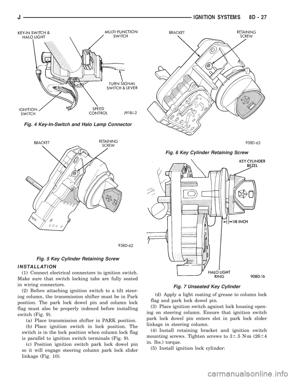
(1) Connect electrical connectors to ignition switch.
Make sure that switch locking tabs are fully seated
in wiring connectors.
(2) Before attaching ignition switch to a tilt steer-
ing column, the transmission shifter must be in Park
position. The park lock dowel pin and column lock
flag must also be properly indexed before installing
switch (Fig. 9).
(a) Place transmission shifter in PARK position.
(b) Place ignition switch in lock position. The
switch is in the lock position when column lock flag
is parallel to ignition switch terminals (Fig. 9).
(c) Position ignition switch park lock dowel pin
so it will engage steering column park lock slider
linkage (Fig. 10).(d) Apply a light coating of grease to column lock
flag and park lock dowel pin.
(3) Place ignition switch against lock housing open-
ing on steering column. Ensure that ignition switch
park lock dowel pin enters slot in park lock slider
linkage in steering column.
(4) Install retaining bracket and ignition switch
mounting screws. Tighten screws to 36.5 Nzm (2664
in. lbs.) torque.
(5) Install ignition lock cylinder:
Fig. 4 Key-In-Switch and Halo Lamp Connector
Fig. 5 Key Cylinder Retaining Screw
Fig. 6 Key Cylinder Retaining Screw
Fig. 7 Unseated Key Cylinder
JIGNITION SYSTEMS 8D - 27