1995 JEEP CHEROKEE electrical wiring
[x] Cancel search: electrical wiringPage 1254 of 2198
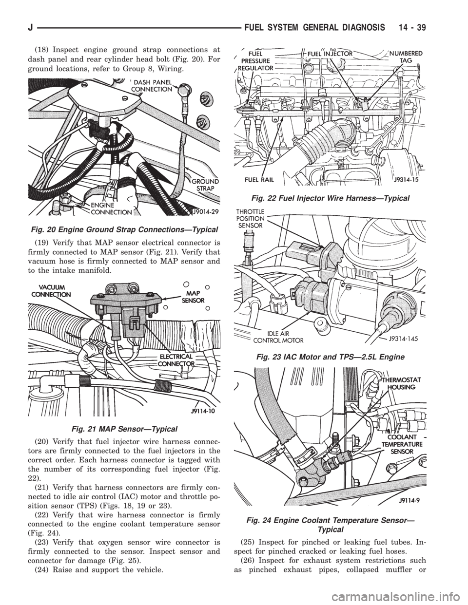
(18) Inspect engine ground strap connections at
dash panel and rear cylinder head bolt (Fig. 20). For
ground locations, refer to Group 8, Wiring.
(19) Verify that MAP sensor electrical connector is
firmly connected to MAP sensor (Fig. 21). Verify that
vacuum hose is firmly connected to MAP sensor and
to the intake manifold.
(20) Verify that fuel injector wire harness connec-
tors are firmly connected to the fuel injectors in the
correct order. Each harness connector is tagged with
the number of its corresponding fuel injector (Fig.
22).
(21) Verify that harness connectors are firmly con-
nected to idle air control (IAC) motor and throttle po-
sition sensor (TPS) (Figs. 18, 19 or 23).
(22) Verify that wire harness connector is firmly
connected to the engine coolant temperature sensor
(Fig. 24).
(23) Verify that oxygen sensor wire connector is
firmly connected to the sensor. Inspect sensor and
connector for damage (Fig. 25).
(24) Raise and support the vehicle.(25) Inspect for pinched or leaking fuel tubes. In-
spect for pinched cracked or leaking fuel hoses.
(26) Inspect for exhaust system restrictions such
as pinched exhaust pipes, collapsed muffler or
Fig. 20 Engine Ground Strap ConnectionsÐTypical
Fig. 21 MAP SensorÐTypical
Fig. 22 Fuel Injector Wire HarnessÐTypical
Fig. 23 IAC Motor and TPSÐ2.5L Engine
Fig. 24 Engine Coolant Temperature SensorÐ
Typical
JFUEL SYSTEM GENERAL DIAGNOSIS 14 - 39
Page 1255 of 2198
plugged catalytic convertor.
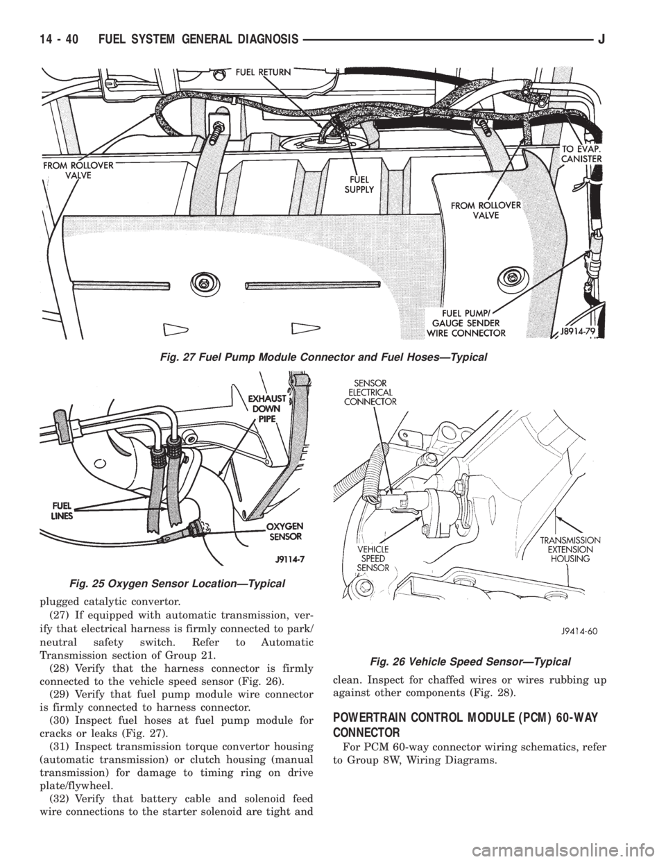
(27) If equipped with automatic transmission, ver-
ify that electrical harness is firmly connected to park/
neutral safety switch. Refer to Automatic
Transmission section of Group 21.
(28) Verify that the harness connector is firmly
connected to the vehicle speed sensor (Fig. 26).
(29) Verify that fuel pump module wire connector
is firmly connected to harness connector.
(30) Inspect fuel hoses at fuel pump module for
cracks or leaks (Fig. 27).
(31) Inspect transmission torque convertor housing
(automatic transmission) or clutch housing (manual
transmission) for damage to timing ring on drive
plate/flywheel.
(32) Verify that battery cable and solenoid feed
wire connections to the starter solenoid are tight andclean. Inspect for chaffed wires or wires rubbing up
against other components (Fig. 28).
POWERTRAIN CONTROL MODULE (PCM) 60-WAY
CONNECTOR
For PCM 60-way connector wiring schematics, refer
to Group 8W, Wiring Diagrams.
Fig. 27 Fuel Pump Module Connector and Fuel HosesÐTypical
Fig. 25 Oxygen Sensor LocationÐTypical
Fig. 26 Vehicle Speed SensorÐTypical
14 - 40 FUEL SYSTEM GENERAL DIAGNOSISJ
Page 1266 of 2198
(8) Disconnect jumper wires from relay and 12 Volt
power source.
If continuity or resistance tests did not pass, re-
place relay. If tests passed, refer to Group 8W, Wiring
Diagrams for additional circuit information. Also re-
fer to the appropriate Powertrain Diagnostic Proce-
dures manual for operation of the DRB scan tool.
STARTER MOTOR RELAY TEST
Refer to Group 8A, Battery/Starting/Charging/Sys-
tem Diagnostics, for starter motor relay testing.
FUEL INJECTOR TEST
To perform a complete test of the fuel injectors and
their circuitry, refer to DRB scan tool and appropri-
ate Powertrain Diagnostics Procedures manual. To
test the injector only, refer to the following:
Disconnect the injector wire connector from the in-
jector. Place an ohmmeter on the injector terminals.
Resistance reading should be approximately 14.5
ohms61.2 ohms at 20ÉC (68ÉF). Proceed to the fol-
lowing Injector Diagnosis chart.When performing
the following tests from the chart, do not leave
electrical current applied to the injector for
longer than five seconds. Damage to injector
coil or internal injector seals could result.
FUEL SYSTEM PRESSURE TEST
Refer to the Fuel Delivery System section of this
group. See Fuel System Pressure Test.
ON-BOARD DIAGNOSTICS (OBD)
The powertrain control module (PCM) has been
programmed to monitor many different circuits of the
fuel injection system. If a problem is sensed in a
monitored circuit often enough to indicate an actual
problem, a Diagnostic Trouble Code (DTC) is stored.
The DTC will be stored in the PCM memory for even-
tual display to the service technician. If the problem
is repaired or ceases to exist, the PCM cancels the
DTC after 51 engine starts.Certain criteria must be met for a diagnostic trou-
ble code (DTC) to be entered into PCM memory. The
criteria may be a specific range of engine rpm, engine
temperature and/or input voltage to the PCM.
It is possible that a DTC for a monitored circuit
may not be entered into memory even though a mal-
function has occurred. This may happen because one
of the DTC criteria for the circuit has not been met.
Example: assume that one of the criteria for the
MAP sensor circuit is that the engine must be oper-
ating between 750 and 2000 rpm to be monitored for
a DTC. If the MAP sensor output circuit shorts to
ground when the engine rpm is above 2400 rpm, a 0
volt input will be seen by the PCM. A DTC will not
be entered into memory because the condition does
not occur within the specified rpm range.
A DTC indicates that the powertrain control mod-
ule (PCM) has recognized an abnormal signal in a
circuit or the system. A DTC may indicate the result
of a failure, but never identify the failed component
directly.
There are several operating conditions that the
PCM does not monitor and set a DTC for. Refer to
the following Monitored Circuits and Non-Monitored
Circuits in this section.
MONITORED CIRCUITS
The powertrain control module (PCM) can detect
certain problems in the fuel injection system.
Open or Shorted Circuit- The PCM can deter-
mine if sensor output (which is the input to PCM) is
within proper range. It also determines if the circuit
is open or shorted.
Output Device Current Flow- The PCM senses
whether the output devices are hooked up.
If there is a problem with the circuit, the PCM
senses whether the circuit is open, shorted to ground
(-), or shorted to (+) voltage.
Oxygen Sensor- The PCM can determine if the
oxygen sensor is switching between rich and lean.
This is, once the system has entered Closed Loop. Re-
fer to Open Loop/Closed Loop Modes Of Operation in
the Component Description/System Operation section
for an explanation of Closed (or Open) Loop opera-
tion.
NON-MONITORED CIRCUITS
The PCM does not monitor the following circuits,
systems or conditions that could have malfunctions
that result in driveability problems. A Diagnostic
Trouble Code (DTC) may not be displayed for these
conditions.
Fuel Pressure:Fuel pressure is controlled by the
vacuum assisted fuel pressure regulator. The PCM
cannot detect a clogged fuel pump inlet filter, clogged
in-line fuel filter, or a pinched fuel supply or return
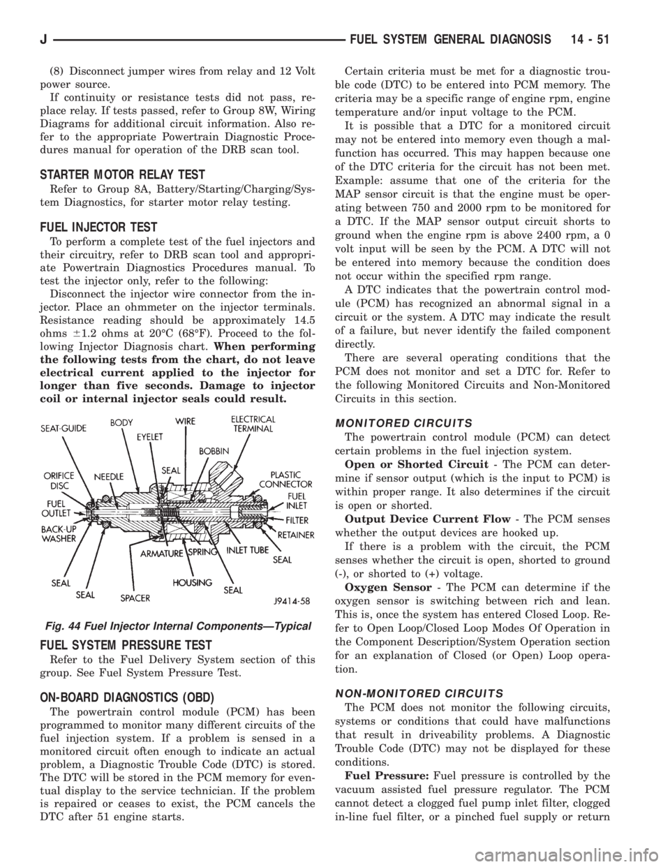
Fig. 44 Fuel Injector Internal ComponentsÐTypical
JFUEL SYSTEM GENERAL DIAGNOSIS 14 - 51
Page 1347 of 2198
GENERAL INFORMATION
The airbag system is a standard equipment safety
device on XJ (Cherokee) models. It is designed to pro-
tect the driver from serious injury, caused by a fron-
tal impact of the vehicle. If the airbag module
assembly is defective and non-deployed, refer to
Chrysler Corporation current return list for proper
handling procedures.
ARMING/DISARMING MECHANISM
BEFORE SERVICING A COLUMN EQUIPPED
WITH AIR BAG, REFER TO GROUP 8M, ELEC-
TRICAL FOR PROPER AND SAFE PROCE-
DURES.
The steering wheel hub incorporates an airbag
Arming/Disarming mechanism and a specially de-
signed nut-blocker. The nut-blocker serves as a safety
to prevent removal of the airbag module until the
unit has been disarmed. A removable plastic cover
plug on the top, outer hub of the steering wheel al-
lows access to the arming screw.
When the airbag module is disarmed, the arming
screw extends upward from the steering wheel hub.
This will prevent installation of the plastic cover
plug. Also, the nut-blocker is retracted to allow ac-
cess to the two upper airbag module mounting nuts.
When the airbag module is armed, the plastic cover
plug will install flush with the outer surface of the
steering wheel hub. In addition, the nut-blocker will
prevent access to the two upper airbag module
mounting nuts.THE FASTENERS, SCREWS, AND BOLTS, ORIG-
INALLY USED FOR THE AIR BAG COMPONENTS,
HAVE SPECIAL COATINGS. THIS HARDWARE IS
SPECIFICALLY DESIGNED FOR THE AIR BAG
SYSTEM. THEY MUST NEVER BE REPLACED
WITH ANY SUBSTITUTES. REPLACE WITH THE
CORRECT FASTENERS PROVIDED IN THE SER-
VICE PACKAGE OR FASTENERS IN THE PARTS
BOOK.
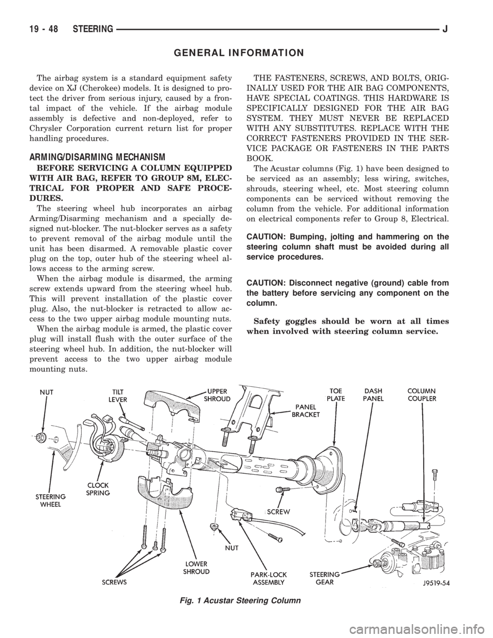
The Acustar columns (Fig. 1) have been designed to
be serviced as an assembly; less wiring, switches,
shrouds, steering wheel, etc. Most steering column
components can be serviced without removing the
column from the vehicle. For additional information
on electrical components refer to Group 8, Electrical.
CAUTION: Bumping, jolting and hammering on the
steering column shaft must be avoided during all
service procedures.
CAUTION: Disconnect negative (ground) cable from
the battery before servicing any component on the
column.
Safety goggles should be worn at all times
when involved with steering column service.
Fig. 1 Acustar Steering Column
19 - 48 STEERINGJ
Page 1353 of 2198
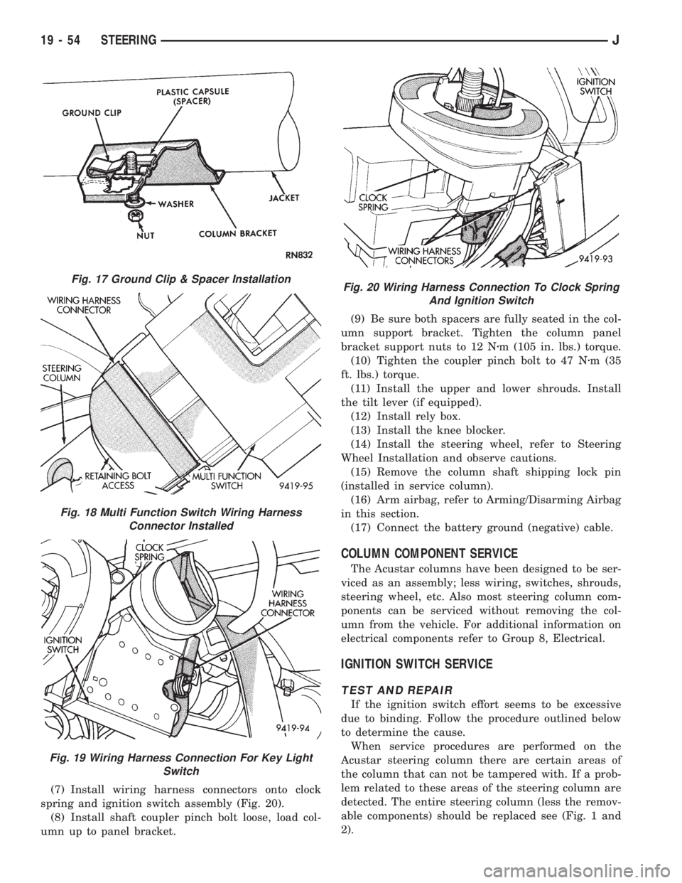
(7) Install wiring harness connectors onto clock
spring and ignition switch assembly (Fig. 20).
(8) Install shaft coupler pinch bolt loose, load col-
umn up to panel bracket.(9) Be sure both spacers are fully seated in the col-
umn support bracket. Tighten the column panel
bracket support nuts to 12 Nzm (105 in. lbs.) torque.
(10) Tighten the coupler pinch bolt to 47 Nzm (35
ft. lbs.) torque.
(11) Install the upper and lower shrouds. Install
the tilt lever (if equipped).
(12) Install rely box.
(13) Install the knee blocker.
(14) Install the steering wheel, refer to Steering
Wheel Installation and observe cautions.
(15) Remove the column shaft shipping lock pin
(installed in service column).
(16) Arm airbag, refer to Arming/Disarming Airbag
in this section.
(17) Connect the battery ground (negative) cable.
COLUMN COMPONENT SERVICE
The Acustar columns have been designed to be ser-
viced as an assembly; less wiring, switches, shrouds,
steering wheel, etc. Also most steering column com-
ponents can be serviced without removing the col-
umn from the vehicle. For additional information on
electrical components refer to Group 8, Electrical.
IGNITION SWITCH SERVICE
TEST AND REPAIR
If the ignition switch effort seems to be excessive
due to binding. Follow the procedure outlined below
to determine the cause.
When service procedures are performed on the
Acustar steering column there are certain areas of
the column that can not be tampered with. If a prob-
lem related to these areas of the steering column are
detected. The entire steering column (less the remov-
able components) should be replaced see (Fig. 1 and
2).
Fig. 17 Ground Clip & Spacer Installation
Fig. 18 Multi Function Switch Wiring Harness
Connector Installed
Fig. 19 Wiring Harness Connection For Key Light
Switch
Fig. 20 Wiring Harness Connection To Clock Spring
And Ignition Switch
19 - 54 STEERINGJ
Page 1918 of 2198
COMPONENT SERVICEÐXJ VEHICLES
INDEX
page page
A/C Recirculating Door Vacuum Motor
Replacement........................... 27
Blower Motor Resistors Replacement.......... 31
Blower Motor/Fan Replacement............... 24
Condenser Filter DrierÐ2.5L Engines.......... 27
CondenserÐ4.0L Engines................... 28
Description.............................. 23
Evaporator Coil........................... 30
Evaporator/Blower Housing.................. 29Expansion Valve.......................... 31
Filter DrierÐ4.0L Engines................... 28
Fin Sensing Cycling Clutch Switch............. 31
Heater and A/C Control Replacement.......... 23
Heater Core............................. 26
Heater Housing Replacement................ 26
Heater/Defroster/Instrument Panel Outlet Vacuum
Motor Replacement...................... 26
DESCRIPTION
The Climate Control System combines air condi-
tioning, heating and ventilating capabilities for vehi-
cles equipped with air conditioning. Vehicles without
air conditioning perform heating and ventilating
functions without the air conditioning evaporator.
Both systems consist basically of 2 parts:
²Blower and Air Inlet Assembly
²Heater Core and Air Distribution Assembly
These unit may be removed separately from under
the instrument panel for service.
HEATER AND A/C CONTROL REPLACEMENT
(1) Disconnect negative cable from battery.
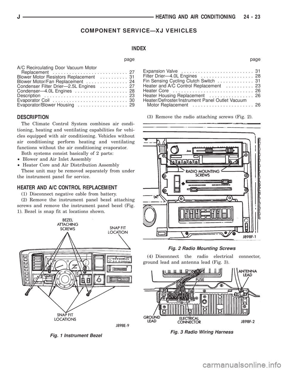
(2) Remove the instrument panel bezel attaching
screws and remove the instrument panel bezel (Fig.
1). Bezel is snap fit at locations shown.(3) Remove the radio attaching screws (Fig. 2).
(4) Disconnect the radio electrical connector,
ground lead and antenna lead (Fig. 3).
Fig. 1 Instrument Bezel
Fig. 2 Radio Mounting Screws
Fig. 3 Radio Wiring Harness
JHEATING AND AIR CONDITIONING 24 - 23
Page 1926 of 2198

(5) Remove expansion valve from the evaporator.
INSTALLATION
Add 30 ml (1 fluid oz.) of refrigerant oil to the A/C
system if the evaporator is replaced.
(1) Install expansion valve on evaporator.
(2) Position evaporator in the housing. Install and
tighten the evaporator retaining screws.
(3) Install cycling clutch switch into evaporator. In-
stall the top of the evaporator housing.
(4) Install the evaporator/blower housing.
(5) Evacuate and charge A/C system as outlined in
this section.
EXPANSION VALVE
REVIEW ALL WARNINGS AND CAUTIONS IN
THIS GROUP BEFORE PERFORMING THIS
OPERATION.
REMOVAL
(1) Recover refrigerant from A/C system.
(2) Remove the coolant bottle and bracket.
(3) Disconnect A/C hoses from the expansion valve
(Fig. 26).
(4) Disconnect expansion valve from the evaporator
core inlet and outlet tubes. Remove the expansion
valve.
INSTALLATION
(1) Install the expansion valve. Connect the expan-
sion valve to the evaporator core inlet and outlet
tubes.
(2) Connect A/C hoses to the expansion valve.
(3) Install the coolant bottle and bracket.(4) Evacuate and charge A/C system as outlined in
this section.
(5) Preform the leak test.
BLOWER MOTOR RESISTORS REPLACEMENT
(1) Remove vacuum motor cover retaining screw
and lower the cover.
(2) Remove blower motor resistor connector, re-
move the resistor retaining screws, and remove resis-
tor.
To install the blower motor resistor reverse the re-
moval procedures.
FIN SENSING CYCLING CLUTCH SWITCH
REMOVAL
(1) Disconnect negative cable from battery.
(2) If equipped with center console remove the con-
sole. Refer to Group 23 body for proper procedure.
(3) Remove lower instrument panel.
(4) Pull the rosebud terminal out of the housing
(Fig. 27).
(5) Disconnect the electrical connection.
(6) Remove the wires from the retaining clip.
(7) Carefully remove the thermostat cycling clutch
switch from the evaporator (Fig. 27).
INSTALLATION
(1) Carefully install cycling switch.
(2) Connect the electrical connection.
(3) Snap the terminal into the hole in the housing.
(4) Install wiring connections.
(5) Install lower instrument panel.
(6) Install console if equipped.
(7) Install negative battery cable.
Fig. 26 Expansion Valve
Fig. 27 Fin Sensing Cycling Clutch Switch
JHEATING AND AIR CONDITIONING 24 - 31
Page 1970 of 2198
DOOR REMOVAL/INSTALLATIONÐXJ.....23-35
DOOR RESTRAINT REPLACEMENTÐXJ . . . 23-41
DOOR SERVICEÐYJ, FULL-METAL......23-142
DOOR SPACER BLOCKSÐTWO-DOOR
VEHICLES, FRONT....................23-53
DOOR STATIONARY WINDOW
GLASSÐXJ, REAR...................23-46
DOOR TRIM PANELÐXJ...............23-31
DOOR TRIM PANELÐYJ, FULL-METAL . . . 23-137
DOOR VACUUM MOTOR, FRESH AIR.....24-34
DOOR VACUUM MOTOR REPLACEMENT,
A/C RECIRCULATING..................24-27
DOOR VENT WINDOW GLASSÐYJ,
FULL-METAL.......................23-137
DOOR WATERDAMÐYJ, FULL-METAL . . . 23-137
DOOR WEATHERSTRIP SEAL
REPLACEMENTÐYJ.................23-142
DOOR WEATHERSTRIP SEALSÐYJ,
FULL-METAL.......................23-141
DOOR WINDOW EXTERIOR
MOLDINGSÐXJ.....................23-54
DOOR WINDOW GLASS AND DOOR
OPENING WEATHERSTRIP SEALSÐXJ....23-55
DOOR WINDOW GLASS REGULATOR
HANDLEÐYJ, FULL-METAL............23-136
DOOR WINDOW GLASS REGULATORÐ
XJ, FRONT..........................23-42
DOOR WINDOW GLASS REGULATORÐ
XJ, REAR...........................23-44
DOOR WINDOW GLASS REGULATORÐ
YJ, FULL-METAL....................23-138
DOOR WINDOW GLASSÐXJ, FRONT.....23-43
DOOR WINDOW GLASSÐXJ, REAR......23-45
DOOR WINDOW GLASSÐYJ, FULL-
METAL............................23-139
DOORÐYJ, HALF-METAL SOFT TOP.....23-134
DOUBLE CARDAN (CV)................16-11
DRAG LINK....................19-16,19-20
DRAINING COOLING SYSTEM............7-21
DRAW FUSE, IGNITION-OFF.............8F-1
DRAW, IGNITION-OFF.................8A-10
DRB SCAN TOOL; BRAKES...............5-3
DRB SCAN TOOL; COOLING SYSTEM.......7-5
DRB SCAN TOOL; EMISSION CONTROL
SYSTEMS...........................25-2
DRB SCAN TOOL; FUEL SYSTEM........14-54
DRB SCAN TOOL; IGNITION SYSTEMS....8D-8
DRIERÐ2.5L ENGINES, CONDENSER
FILTER.............................24-27
DRIERÐ4.0L ENGINES, FILTER.........24-28
DRIP RAIL MOLDINGÐXJ.............23-25
DRIVE (4WD) SWITCH, FOUR-WHEEL;
INSTRUMENT CLUSTER (XJ-RHD).....8W-40-2
DRIVE (4WD) SWITCH, FOUR-WHEEL;
TRANSMISSION CONTROLS (XJ-RHD) . . 8W-31-1
DRIVE, AUTOMATIC BELT TENSIONERÐ
XJ MODELS WITH RIGHT HAND..........7-42
DRIVE AXLE ASSEMBLY
REPLACEMENTÐXJ VEHICLES; FRONT
SUSPENSION AND AXLE................2-23
DRIVE AXLE ASSEMBLY
REPLACEMENTÐXJ VEHICLES; REAR
SUSPENSION AND AXLES...........3-14,3-31
DRIVE AXLE ASSEMBLY
REPLACEMENTÐYJ VEHICLES; FRONT
SUSPENSION AND AXLE................2-24
DRIVE AXLE ASSEMBLY
REPLACEMENTÐYJ VEHICLES; REAR
SUSPENSION AND AXLES
...............3-14
DRIVE AXLE, FRONT
....................2-3
DRIVE BELT, ACCESSORY
...............0-21
DRIVE BELT DIAGNOSIS (CONT.),
SERPENTINE
.........................7-40
DRIVE BELT DIAGNOSIS, SERPENTINE
.....7-39
DRIVE, BELT SERVICEÐEXCEPT RIGHT
HAND
...............................7-40
DRIVE, BELT SERVICEÐXJ MODELS
WITH RIGHT HAND
....................7-42
DRIVE BELT TENSION
..................7-45
DRIVE BELTS, ENGINE ACCESSORY
.......7-38
DRIVE GEAR, SPEED SENSOR
ROTORÐSPEEDOMETER
.............21-193
DRIVE, GENERATOR REMOVE/INSTALLÐ
LEFT-HAND
..........................8B-6
DRIVE, GENERATOR REMOVE/INSTALLÐ
RIGHT-HAND
.........................8B-7
DRIVE PULLEY REPLACEMENT
..........19-13DRIVE (RHD), BELT TENSIONÐEXCEPT
RIGHT HAND.........................7-38
DRIVE (RHD), BELT TENSIONÐRIGHT
HAND...............................7-38
DRIVE (RHD) MODELS, BELT TENSIONÐ
EXCEPT RIGHT HAND..................7-45
DRIVE SHAFTS.......................0-26
DRIVE VEHICLES, RIGHT HAND..........23-1
DRIVE, VISCOUS FAN..................7-34
DRIVELINE SNAP; FRONT SUSPENSION
AND AXLE...........................2-19
DRIVELINE SNAP; REAR SUSPENSION
AND AXLES..........................3-10
DRIVELINE VIBRATION.................16-3
DRIVER'S DOOR JAMB SWITCH.....8U-1,8U-2
DRIVER'S POWER LOCK SWITCHÐ2-
DOOR (LHD).........................8P-3
DRIVER'S POWER LOCK SWITCHÐ2-
DOOR (RHD).........................8P-4
DRIVER'S POWER LOCK SWITCHÐ4-
DOOR..............................8P-5
DRIVER'S POWER WINDOW SWITCHÐ
2-DOOR (LHD).......................8S-4
DRIVER'S POWER WINDOW SWITCHÐ
2-DOOR (RHD).......................8S-5
DRIVER'S POWER WINDOW SWITCHÐ
4-DOOR.............................8S-3
DRIVER'S SEAT BELT SWITCH.......8U-1,8U-3
DRIVETRAIN.........................0-22
DRL MODULE REPLACEMENTÐXJ.......8L-15
DRL MODULE REPLACEMENTÐYJ........8L-30
DRUM BRAKE ADJUSTMENT............5-57
DRUM BRAKES.......................5-55
DRUM BRAKESHOE INSTALLATION.......5-55
DRUM BRAKESHOE REMOVAL...........5-55
DRUM REFINISHING, BRAKE............5-58
DRUMÐREAR SUPPORT OVERHAUL,
OVERRUNNING CLUTCHÐLOW-
REVERSE..........................21-125
DUCT, DEFROSTER NOZZLE............24-33
DUCT, FRESH AIR INTAKE..............24-34
ECU AND HCU DIAGNOSIS, ANTILOCK......5-3
ECU INSTALLATION (XJ MODELS)........5-40
ECU OPERATION......................5-37
ECU REMOVAL (XJ MODELS)............5-40
ECU REMOVAL/INSTALLATION (YJ
MODELS)............................5-41
EDGE GUARD/EDGE PROTECTOR
STRIPÐXJ, DOOR....................23-54
EFFECTS OF INCORRECT FLUID LEVEL....21-71
EFFORT, HARD PEDAL OR HIGH PEDAL.....5-6
ELECTRIC COOLING FANÐXJ MODELS
WITH 4.0L 6-CYLINDER ENGINE,
AUXILIARY..........................7-35
ELECTRICAL CONTROL, FUEL PUMP......14-5
ELECTRONIC CONTROL UNIT (ECU).......5-34
ELECTROSTATIC DISCHARGE (ESD)
SENSITIVE DEVICES; WIRING
DIAGRAMSÐGENERAL INFORMATION
(XJ)...............................8W-2
ELEMENT, AIR CLEANER; EMISSION
CONTROL SYSTEMS...................25-7
ELEMENT, AIR CLEANER; FUEL SYSTEM . . 14-59
ELEMENT, AIR CLEANER; LUBRICATION
AND MAINTENANCE...................0-18
ELEMENT TEST, OXYGEN SENSOR (O2S)
HEATING...........................14-48
ELEMENTS, HEATER; POWER MIRRORS
(XJ-RHD).........................8W-62-1
EMISSION CONTROL INFORMATION
(VECI) LABEL, VEHICLE.................25-1
EMISSION CONTROL SYSTEM...........0-20
EMISSION CONTROL SYSTEM
MAINTENANCE........................0-4
EMISSION CONTROLS..................25-4
EMR LAMPÐPCM OUTPUT............14-27
ENGINE ACCESSORY DRIVE BELTS.......7-38
ENGINE AND TRANSMISSION/TRANSFER
CASE IDENTIFICATION...............Intro.-5
ENGINE ASSEMBLY (SHORT BLOCK),
SERVICE.............................9-4
ENGINE ASSEMBLYÐXJ VEHICLES
. . . 9-18,9-59
ENGINE ASSEMBLYÐYJ VEHICLES
. . . 9-20,9-62
ENGINE, AUXILIARY ELECTRIC COOLING
FANÐXJ MODELS WITH 4.0L
6-CYLINDER
.........................7-35
ENGINE BLOCK HEATER
................7-44
ENGINE BREAK-IN
.....................0-15ENGINE COOLANT TEMPERATURE
GAUGE; INSTRUMENT CLUSTER (XJ) . . 8W-40-1
ENGINE COOLANT TEMPERATURE
SENSOR; FUEL SYSTEM...............14-60
ENGINE COOLANT TEMPERATURE
SENSOR; FUEL/IGNITION (XJ)........8W-30-3
ENGINE COOLANT TEMPERATURE
SENSOR; FUEL/IGNITION (YJ)........8W-30-3
ENGINE COOLANT TEMPERATURE
SENSOR; IGNITION SYSTEMS......8D-19,8D-5
ENGINE COOLANT TEMPERATURE
SENSOR; FUEL/IGNITION (XJ-RHD)....8W-30-3
ENGINE COOLANT TEMPERATURE
SENSOR TEST; FUEL SYSTEM..........14-46
ENGINE COOLANT TEMPERATURE
SENSOR TEST; IGNITION SYSTEMS.......8D-9
ENGINE COOLANT TEMPERATURE
SENSORÐPCM INPUT................14-23
ENGINE COOLANT TEMPERATURE
WARNING LAMP; INSTRUMENT
CLUSTER (XJ).....................8W-40-1
ENGINE COOLANT TEMPERATURE
WARNING LAMP; INSTRUMENT
CLUSTER (XJ-RHD)................8W-40-1
ENGINE COOLING SYSTEM..............0-18
ENGINE CYLINDER HEAD...........9-25,9-67
ENGINE CYLINDER HEAD COVER.....9-22,9-64
ENGINE CYLINDER HEAD GASKET
FAILURE DIAGNOSIS....................9-5
ENGINE DAMPER.....................9-17
ENGINE DIAGNOSIS....................9-5
ENGINE, DIAGRAM INDEXÐ2.5L;
FUEL/IGNITION (XJ)..................8W-30-6
ENGINE, DIAGRAM INDEXÐ4.0L;
FUEL/IGNITION (XJ)................8W-30-6
ENGINE, ENGINE EXHAUST MANIFOLDÐ
2.5L................................11-7
ENGINE, ENGINE EXHAUST MANIFOLDÐ
4.0L................................11-7
ENGINE, ENGINE FIRING ORDERÐ2.5L
4-CYLINDER........................8D-32
ENGINE, ENGINE FIRING ORDERÐ4.0L
6-CYLINDER........................8D-32
ENGINE EXHAUST MANIFOLDÐ2.5L
ENGINE.............................11-7
ENGINE EXHAUST MANIFOLDÐ4.0L
ENGINE.............................11-7
ENGINE FIRING ORDERÐ2.5L
4-CYLINDER ENGINE.................8D-32
ENGINE FIRING ORDERÐ4.0L
6-CYLINDER ENGINE.................8D-32
ENGINE, INTAKE MANIFOLDÐ2.5L........11-7
ENGINE, INTAKE MANIFOLDÐ4.0L........11-8
ENGINE MAINTENANCE.................0-15
ENGINE MOUNTÐREAR............9-16,9-57
ENGINE MOUNTSÐFRONT..........9-14,9-56
ENGINE OIL..........................0-15
ENGINE OIL CHANGE AND FILTER
REPLACEMENT.......................0-16
ENGINE OIL FILTER....................0-17
ENGINE OIL PRESSURE.................9-7
ENGINE ONLY, POWER STEERING
PRESSURE SWITCHÐ2.5L.............14-63
ENGINE ONLY, TORQUE CONVERTER
CLUTCH (TCC) SOLENOID AND
RELAYÐ2.5L; TRANSMISSION
CONTROLS (XJ)...................8W-31-1
ENGINE ONLY, TRANSMISSION
CONTROL MODULEÐ4.0L;
TRANSMISSION CONTROLS (XJ)......8W-31-1
ENGINE PERFORMANCE.................9-2
ENGINE SERVICE PROCEDURES, 2.5L.....9-13
ENGINE SERVICE PROCEDURES, 4.0L.....9-55
ENGINE SPECIFICATIONS...........9-52,9-93
ENGINE, VACUUM ROUTING
SCHEMATICÐ2.5L 4 CYLINDER..........25-3
ENGINE, VACUUM ROUTING
SCHEMATICÐ4.0L 6 CYLINDER..........25-3
ENGINES, CONDENSER FILTER
DRIERÐ2.5L........................24-27
ENGINES, CONDENSERÐ4.0L..........24-28
ENGINES, FILTER DRIERÐ4.0L
.........24-28
ENGINES, FUEL USAGE STATEMENTÐ
GAS
................................0-19
ENGLISH/SAE CONVERSION, METRIC
. . Intro.-11
ENTRY MODULE, KEYLESS
.........8P-1,8P-7
ENTRY MODULE, REMOTE KEYLESS;
POWER DOOR LOCKS (XJ)
...........8W-61-1
JINDEX 9
Description Group-Page Description Group-Page Description Group-Page