1995 JEEP CHEROKEE alarm
[x] Cancel search: alarmPage 178 of 2198
(2) Align and attach harness connector to ECU.
Slide connector into engagement with tangs on ECU.
Then tilt connector downward and into engagement
with ECU pin terminals. Exercise care as pin termi-
nals can be damaged if connector is forced into place.
(3) Connect harness to security alarm module, if
equipped.
(4) Position ECU bracket under instrument panel.
(5) Install and tighten ECU mounting bracket
bolts/nuts to 8-14 Nzm (75- 125 in. lbs.) torque.
(6) Install trim panel on instrument panel, if re-
moved.
ECU REMOVAL/INSTALLATION (YJ MODELS)
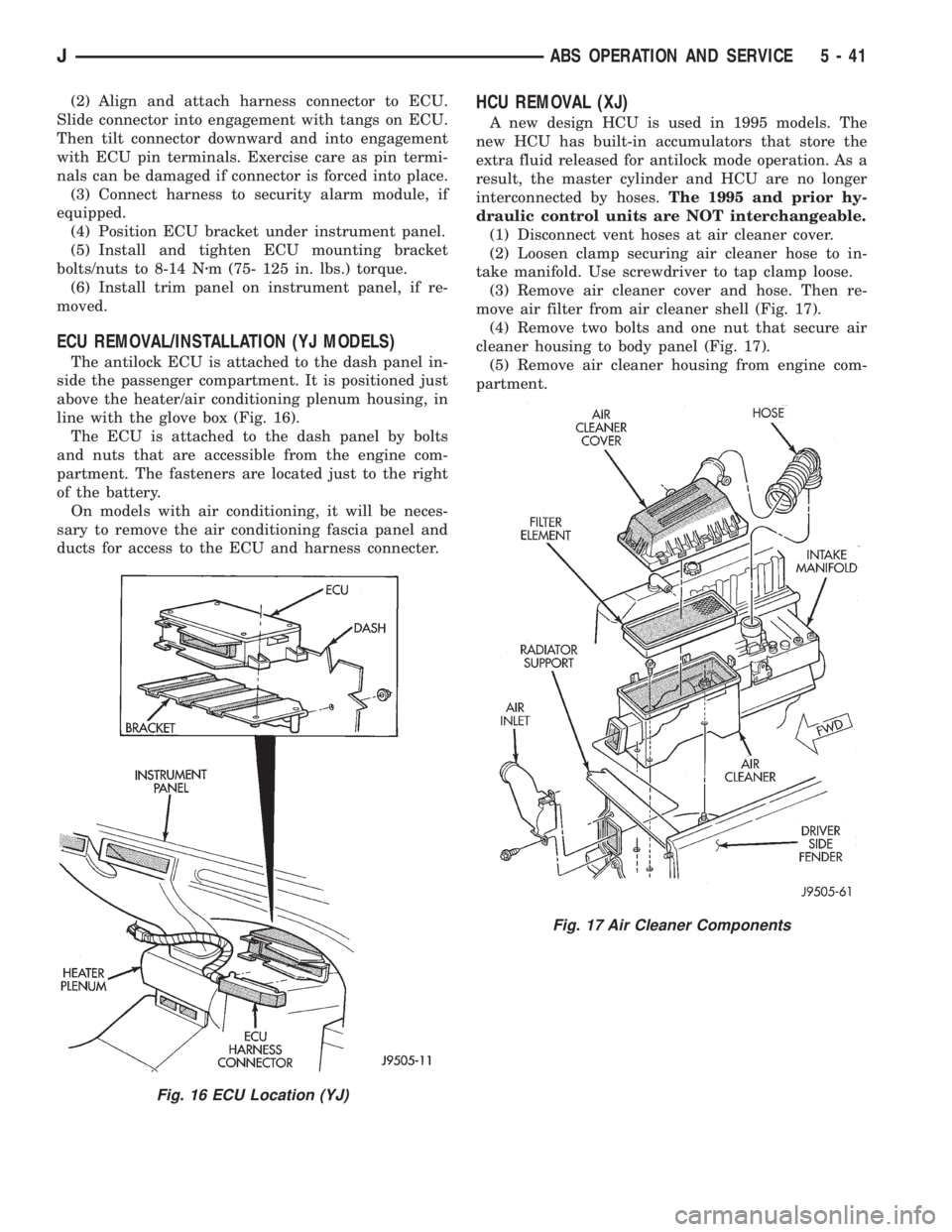
The antilock ECU is attached to the dash panel in-
side the passenger compartment. It is positioned just
above the heater/air conditioning plenum housing, in
line with the glove box (Fig. 16).
The ECU is attached to the dash panel by bolts
and nuts that are accessible from the engine com-
partment. The fasteners are located just to the right
of the battery.
On models with air conditioning, it will be neces-
sary to remove the air conditioning fascia panel and
ducts for access to the ECU and harness connecter.
HCU REMOVAL (XJ)
A new design HCU is used in 1995 models. The
new HCU has built-in accumulators that store the
extra fluid released for antilock mode operation. As a
result, the master cylinder and HCU are no longer
interconnected by hoses.The 1995 and prior hy-
draulic control units are NOT interchangeable.
(1) Disconnect vent hoses at air cleaner cover.
(2) Loosen clamp securing air cleaner hose to in-
take manifold. Use screwdriver to tap clamp loose.
(3) Remove air cleaner cover and hose. Then re-
move air filter from air cleaner shell (Fig. 17).
(4) Remove two bolts and one nut that secure air
cleaner housing to body panel (Fig. 17).
(5) Remove air cleaner housing from engine com-
partment.
Fig. 16 ECU Location (YJ)
Fig. 17 Air Cleaner Components
JABS OPERATION AND SERVICE 5 - 41
Page 463 of 2198
INTERIOR LAMPS
INDEX
page page
Dome Lamp ReplacementÐXJ............... 17
Dome/Courtesy Lamp Service InformationÐXJ . . . 16
Dome/Courtesy Lamp Trouble DiagnosisÐXJ.... 16Lighted Vanity Mirror Trouble DiagnosisÐXJ..... 16
Lighted Vanity MirrorÐXJ................... 16
Overhead ConsoleÐXJ..................... 17
DOME/COURTESY LAMP SERVICE
INFORMATIONÐXJ
Voltage is applied at all times via the dome lamp
fuse to each of the interior lamp bulbs. The interior
lamp bulbs illuminate when they are connected to
body ground via the switch:
²Headlamp switch.
²Glove box switch.
²Door pillar switch.
²Liftgate switch (if the cargo lamp is ON).
If equipped with Security Alarm Module, refer to
Group 8Q, Vehicle Theft Security System.
DOME/COURTESY LAMP TROUBLE DIAGNOSISÐ
XJ
ALL LAMPS INOPERATIVE
(1) Rotate the headlamp switch rheostat clockwise.
The lamps should light. If not OK, remove, inspect
and test the dome lamp fuse. Replace if bad.
(2) If the fuse is OK, repair the open circuit in the
wire harness to vehicle body ground.
ONE LAMP INOPERATIVE
(1) Measure the resistance across the bulb holder
terminals. The ohmmeter should indicate zero ohms.
If not, replace the bulb.
(2) Measure the voltage between the voltage side
of the bulb holder and vehicle body ground. The volt-
meter should indicate battery voltage. If not, repair
the open circuit in the wire harness to the splice.
LAMPS INOPERATIVE WITH ONE OR MORE
DOORS OPENED
(1) Remove the inoperative switch from the door
pillar and connect the switch wire directly to ground.
The lamp should light.
(2) If not, check for an open circuit in black
(ground) wire. Repair as necessary. If lamps still do
not light, replace the switch.
LIGHTED VANITY MIRRORÐXJ
SERVICE INFORMATION
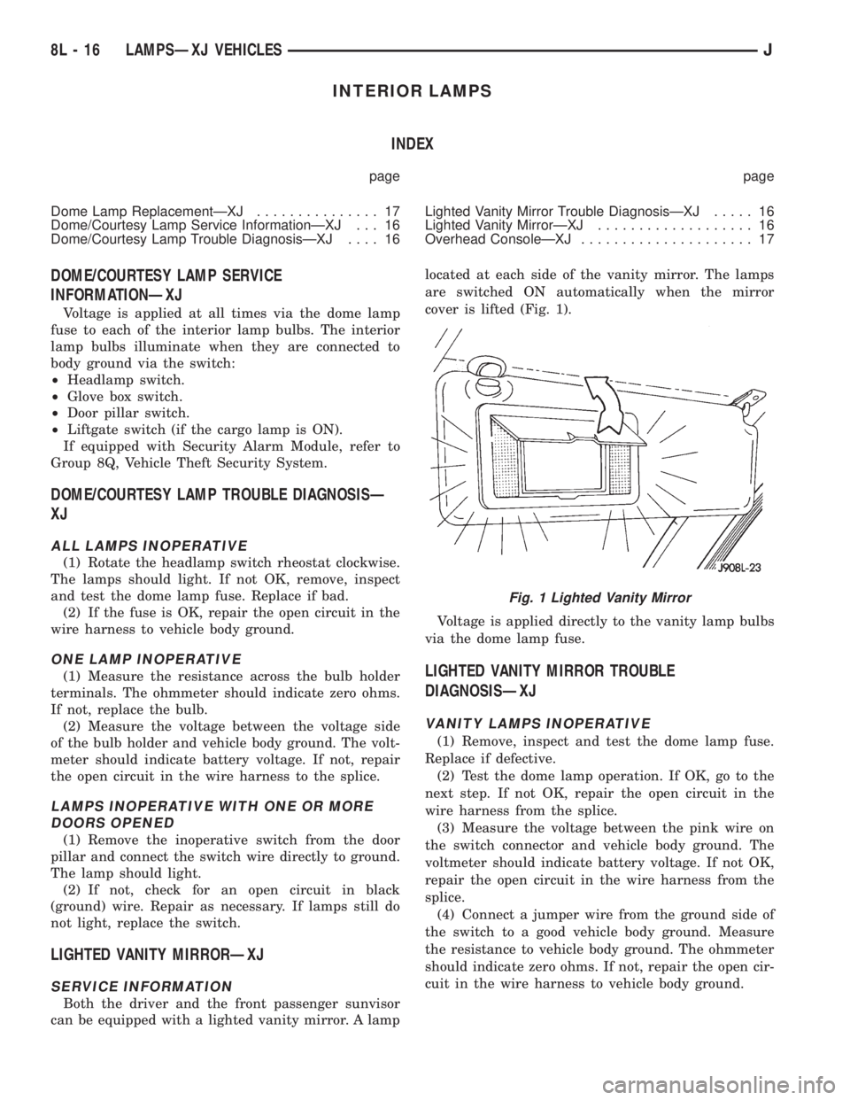
Both the driver and the front passenger sunvisor
can be equipped with a lighted vanity mirror. A lamplocated at each side of the vanity mirror. The lamps
are switched ON automatically when the mirror
cover is lifted (Fig. 1).
Voltage is applied directly to the vanity lamp bulbs
via the dome lamp fuse.
LIGHTED VANITY MIRROR TROUBLE
DIAGNOSISÐXJ
VANITY LAMPS INOPERATIVE
(1) Remove, inspect and test the dome lamp fuse.
Replace if defective.
(2) Test the dome lamp operation. If OK, go to the
next step. If not OK, repair the open circuit in the
wire harness from the splice.
(3) Measure the voltage between the pink wire on
the switch connector and vehicle body ground. The
voltmeter should indicate battery voltage. If not OK,
repair the open circuit in the wire harness from the
splice.
(4) Connect a jumper wire from the ground side of
the switch to a good vehicle body ground. Measure
the resistance to vehicle body ground. The ohmmeter
should indicate zero ohms. If not, repair the open cir-
cuit in the wire harness to vehicle body ground.
Fig. 1 Lighted Vanity Mirror
8L - 16 LAMPSÐXJ VEHICLESJ
Page 1768 of 2198
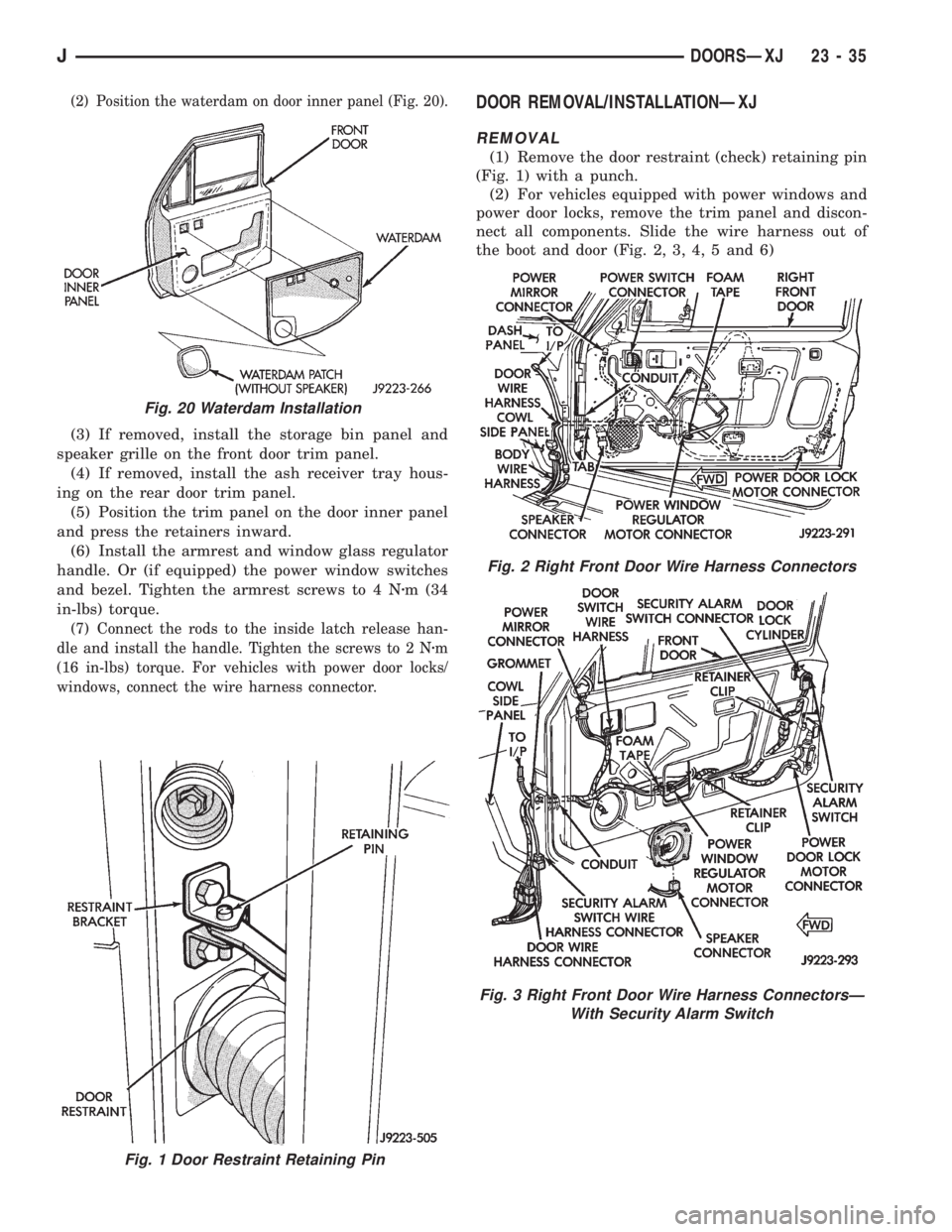
(2) Position the waterdam on door inner panel (Fig. 20).
(3) If removed, install the storage bin panel and
speaker grille on the front door trim panel.
(4) If removed, install the ash receiver tray hous-
ing on the rear door trim panel.
(5) Position the trim panel on the door inner panel
and press the retainers inward.
(6) Install the armrest and window glass regulator
handle. Or (if equipped) the power window switches
and bezel. Tighten the armrest screws to 4 Nzm (34
in-lbs) torque.
(7) Connect the rods to the inside latch release han-
dle and install the handle. Tighten the screws to 2 Nzm
(16 in-lbs) torque. For vehicles with power door locks/
windows, connect the wire harness connector.
DOOR REMOVAL/INSTALLATIONÐXJ
REMOVAL
(1) Remove the door restraint (check) retaining pin
(Fig. 1) with a punch.
(2) For vehicles equipped with power windows and
power door locks, remove the trim panel and discon-
nect all components. Slide the wire harness out of
the boot and door (Fig. 2, 3, 4, 5 and 6)
Fig. 1 Door Restraint Retaining Pin
Fig. 20 Waterdam Installation
Fig. 2 Right Front Door Wire Harness Connectors
Fig. 3 Right Front Door Wire Harness ConnectorsÐ
With Security Alarm Switch
JDOORSÐXJ 23 - 35
Page 1780 of 2198
(3) Remove the window weatherstrip seals from
the door.
(4) Remove the trim panel and waterdam from
door inner panel.
(5) Remove the channel/division bar screws. Drill
out the rivet head to remove it from the inner panel.
(6) Tilt the channel/division bar forward and re-
move it from the door.
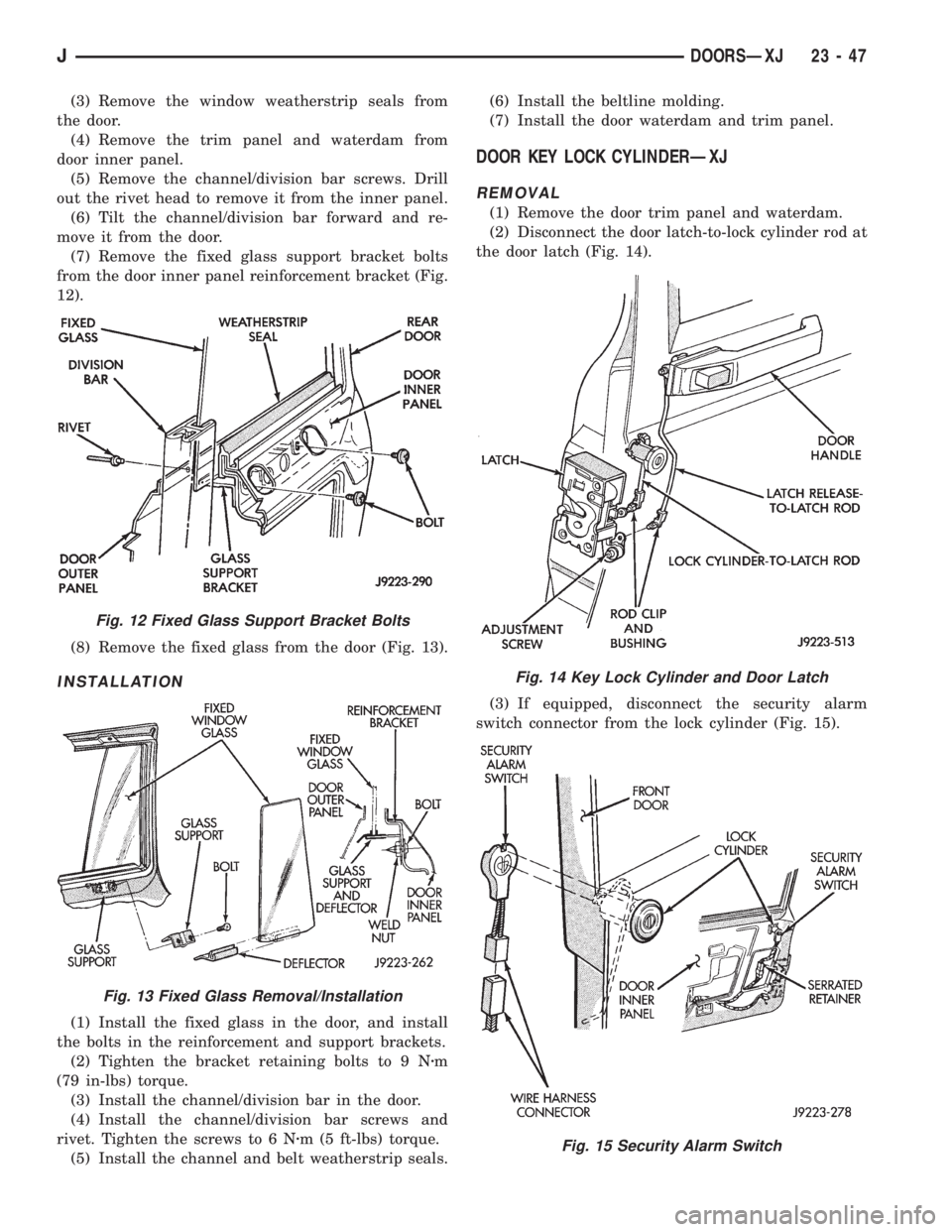
(7) Remove the fixed glass support bracket bolts
from the door inner panel reinforcement bracket (Fig.
12).
(8) Remove the fixed glass from the door (Fig. 13).
INSTALLATION
(1) Install the fixed glass in the door, and install
the bolts in the reinforcement and support brackets.
(2) Tighten the bracket retaining bolts to 9 Nzm
(79 in-lbs) torque.
(3) Install the channel/division bar in the door.
(4) Install the channel/division bar screws and
rivet. Tighten the screws to 6 Nzm (5 ft-lbs) torque.
(5) Install the channel and belt weatherstrip seals.(6) Install the beltline molding.
(7) Install the door waterdam and trim panel.
DOOR KEY LOCK CYLINDERÐXJ
REMOVAL
(1) Remove the door trim panel and waterdam.
(2) Disconnect the door latch-to-lock cylinder rod at
the door latch (Fig. 14).
(3) If equipped, disconnect the security alarm
switch connector from the lock cylinder (Fig. 15).
Fig. 12 Fixed Glass Support Bracket Bolts
Fig. 13 Fixed Glass Removal/Installation
Fig. 14 Key Lock Cylinder and Door Latch
Fig. 15 Security Alarm Switch
JDOORSÐXJ 23 - 47
Page 1781 of 2198
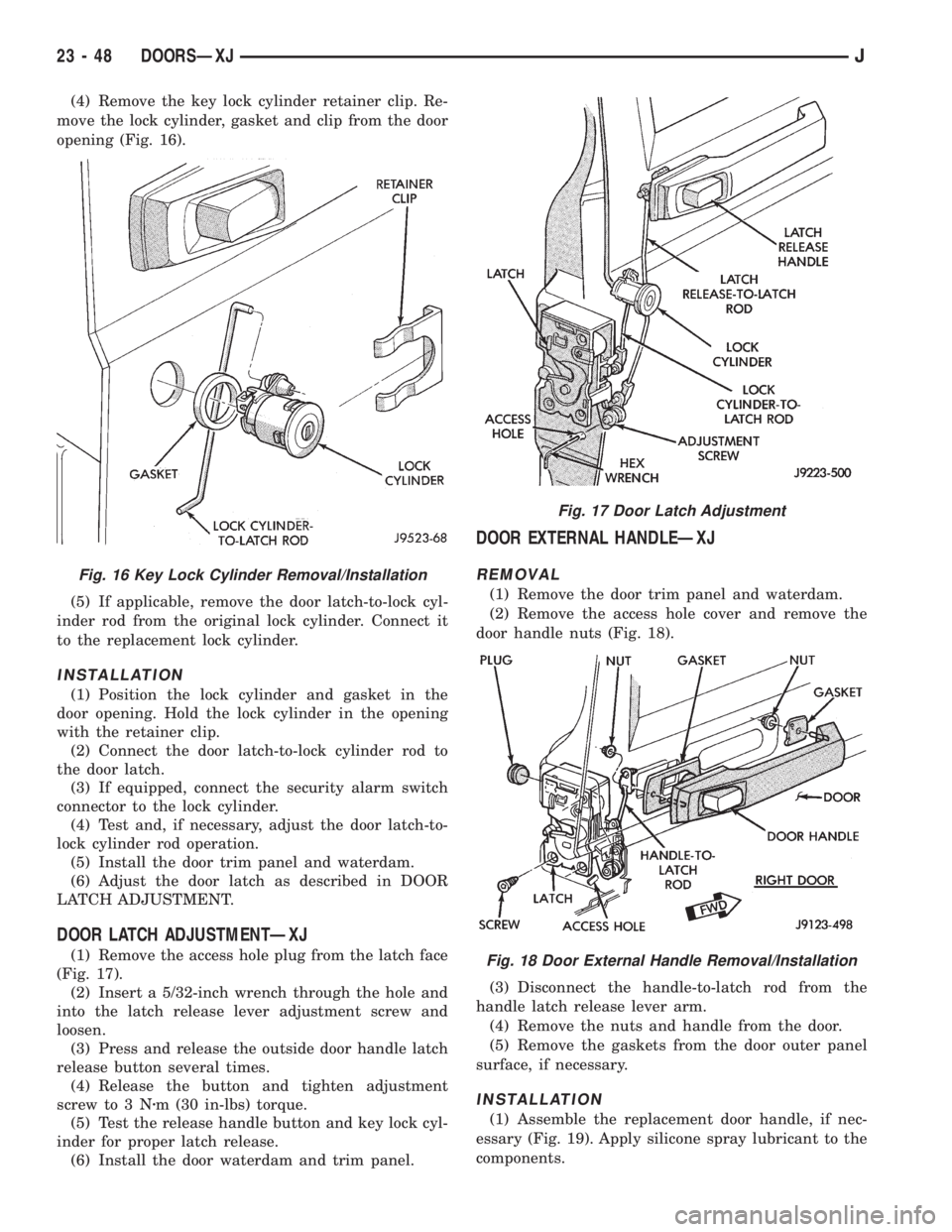
(4) Remove the key lock cylinder retainer clip. Re-
move the lock cylinder, gasket and clip from the door
opening (Fig. 16).
(5) If applicable, remove the door latch-to-lock cyl-
inder rod from the original lock cylinder. Connect it
to the replacement lock cylinder.
INSTALLATION
(1) Position the lock cylinder and gasket in the
door opening. Hold the lock cylinder in the opening
with the retainer clip.
(2) Connect the door latch-to-lock cylinder rod to
the door latch.
(3) If equipped, connect the security alarm switch
connector to the lock cylinder.
(4) Test and, if necessary, adjust the door latch-to-
lock cylinder rod operation.
(5) Install the door trim panel and waterdam.
(6) Adjust the door latch as described in DOOR
LATCH ADJUSTMENT.
DOOR LATCH ADJUSTMENTÐXJ
(1) Remove the access hole plug from the latch face
(Fig. 17).
(2) Insert a 5/32-inch wrench through the hole and
into the latch release lever adjustment screw and
loosen.
(3) Press and release the outside door handle latch
release button several times.
(4) Release the button and tighten adjustment
screw to 3 Nzm (30 in-lbs) torque.
(5) Test the release handle button and key lock cyl-
inder for proper latch release.
(6) Install the door waterdam and trim panel.
DOOR EXTERNAL HANDLEÐXJ
REMOVAL
(1) Remove the door trim panel and waterdam.
(2) Remove the access hole cover and remove the
door handle nuts (Fig. 18).
(3) Disconnect the handle-to-latch rod from the
handle latch release lever arm.
(4) Remove the nuts and handle from the door.
(5) Remove the gaskets from the door outer panel
surface, if necessary.
INSTALLATION
(1) Assemble the replacement door handle, if nec-
essary (Fig. 19). Apply silicone spray lubricant to the
components.
Fig. 16 Key Lock Cylinder Removal/Installation
Fig. 17 Door Latch Adjustment
Fig. 18 Door External Handle Removal/Installation
23 - 48 DOORSÐXJJ