1995 JEEP CHEROKEE dead battery
[x] Cancel search: dead batteryPage 315 of 2198

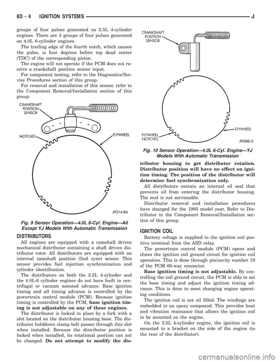
groups of four pulses generated on 2.5L 4-cylinder
engines. There are 3 groups of four pulses generated
on 4.0L 6-cylinder engines.
The trailing edge of the fourth notch, which causes
the pulse, is four degrees before top dead center
(TDC) of the corresponding piston.
The engine will not operate if the PCM does not re-
ceive a crankshaft position sensor input.
For component testing, refer to the Diagnostics/Ser-
vice Procedures section of this group.
For removal and installation of this sensor, refer to
the Component Removal/Installation section of this
group.
DISTRIBUTORS
All engines are equipped with a camshaft driven
mechanical distributor containing a shaft driven dis-
tributor rotor. All distributors are equipped with an
internal camshaft position (fuel sync) sensor. This
sensor provides fuel injection synchronization and
cylinder identification.
The distributors on both the 2.5L 4-cylinder and
the 4.0L-6 cylinder engines do not have built in cen-
trifugal or vacuum assisted advance. Base ignition
timing and all timing advance is controlled by the
powertrain control module (PCM). Because ignition
timing is controlled by the PCM,base ignition tim-
ing is not adjustable on any of these engines.
The distributor is locked in place by a fork with a
slot located on the distributor housing base. The dis-
tributor holddown clamp bolt passes through this slot
when installed. Because the distributor position is
locked when installed, its rotational position can not
be changed.Do not attempt to modify the dis-tributor housing to get distributor rotation.
Distributor position will have no effect on igni-
tion timing. The position of the distributor will
determine fuel synchronization only.
All distributors contain an internal oil seal that
prevents oil from entering the distributor housing.
The seal is not serviceable.
Distributor removal and installation procedures
have changed for the 1995 model year. Refer to Dis-
tributor in the Component Removal/Installation sec-
tion of this group.
IGNITION COIL
Battery voltage is supplied to the ignition coil pos-
itive terminal from the ASD relay.
The powertrain control module (PCM) opens and
closes the ignition coil ground circuit for ignition coil
operation. This is done through pin/cavity number 19
of the PCM 60-way connector.
Base ignition timing is not adjustable.By con-
trolling the coil ground circuit, the PCM is able to set
the base timing and adjust the ignition timing ad-
vance. This is done to meet changing engine operat-
ing conditions.
The ignition coil is not oil filled. The windings are
embedded in an epoxy compound. This provides heat
and vibration resistance that allows the ignition coil
to be mounted on the engine.
On the 2.5L 4-cylinder engine, the ignition coil is
mounted to a bracket on the side of the engine (to
the rear of the distributor).
Fig. 9 Sensor OperationÐ4.0L 6-Cyl. EngineÐAll
Except YJ Models With Automatic Transmission
Fig. 10 Sensor OperationÐ4.0L 6-Cyl. EngineÐYJ
Models With Automatic Transmission
8D - 4 IGNITION SYSTEMSJ
Page 331 of 2198

REMOVALÐ2.5L OR 4.0L ENGINE
(1) Disconnect the negative battery cable at the
battery.
(2) Disconnect coil secondary cable at coil.
(3) Remove distributor cap from distributor (2
screws). Do not remove cables from cap. Do not re-
move rotor.
(4) Disconnect the distributor wiring harness from
the main engine harness.
(5) Remove the cylinder number 1 spark plug.
(6) Hold a finger over the open spark plug hole.
Rotate the engine at the vibration dampener bolt un-
til compression (pressure) is felt.
Slowly continue to rotate the engine. Do this until
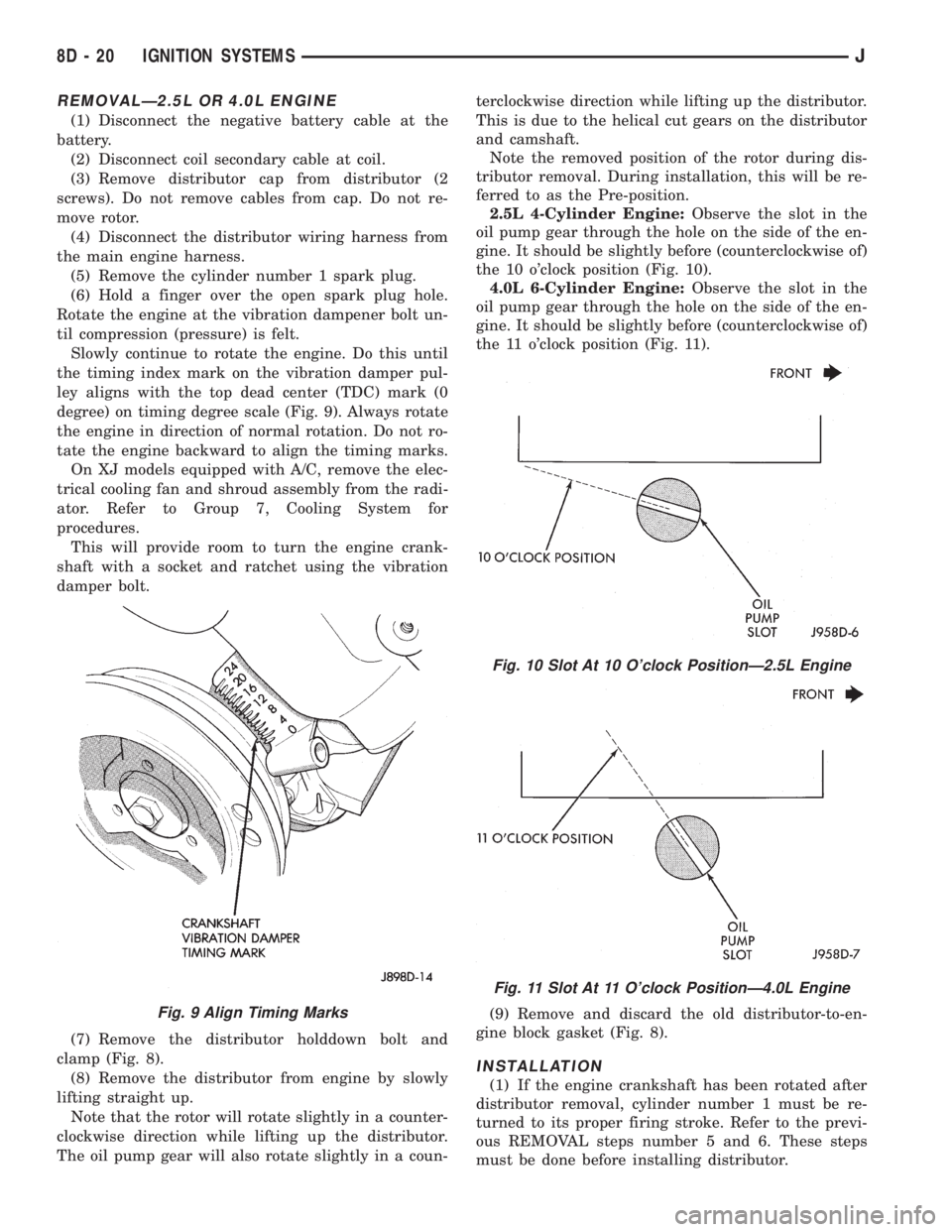
the timing index mark on the vibration damper pul-
ley aligns with the top dead center (TDC) mark (0
degree) on timing degree scale (Fig. 9). Always rotate
the engine in direction of normal rotation. Do not ro-
tate the engine backward to align the timing marks.
On XJ models equipped with A/C, remove the elec-
trical cooling fan and shroud assembly from the radi-
ator. Refer to Group 7, Cooling System for
procedures.
This will provide room to turn the engine crank-
shaft with a socket and ratchet using the vibration
damper bolt.
(7) Remove the distributor holddown bolt and
clamp (Fig. 8).
(8) Remove the distributor from engine by slowly
lifting straight up.
Note that the rotor will rotate slightly in a counter-
clockwise direction while lifting up the distributor.
The oil pump gear will also rotate slightly in a coun-terclockwise direction while lifting up the distributor.
This is due to the helical cut gears on the distributor
and camshaft.
Note the removed position of the rotor during dis-
tributor removal. During installation, this will be re-
ferred to as the Pre-position.
2.5L 4-Cylinder Engine:Observe the slot in the
oil pump gear through the hole on the side of the en-
gine. It should be slightly before (counterclockwise of)
the 10 o'clock position (Fig. 10).
4.0L 6-Cylinder Engine:Observe the slot in the
oil pump gear through the hole on the side of the en-
gine. It should be slightly before (counterclockwise of)
the 11 o'clock position (Fig. 11).
(9) Remove and discard the old distributor-to-en-
gine block gasket (Fig. 8).
INSTALLATION
(1) If the engine crankshaft has been rotated after
distributor removal, cylinder number 1 must be re-
turned to its proper firing stroke. Refer to the previ-
ous REMOVAL steps number 5 and 6. These steps
must be done before installing distributor.
Fig. 9 Align Timing Marks
Fig. 10 Slot At 10 O'clock PositionÐ2.5L Engine
Fig. 11 Slot At 11 O'clock PositionÐ4.0L Engine
8D - 20 IGNITION SYSTEMSJ
Page 333 of 2198

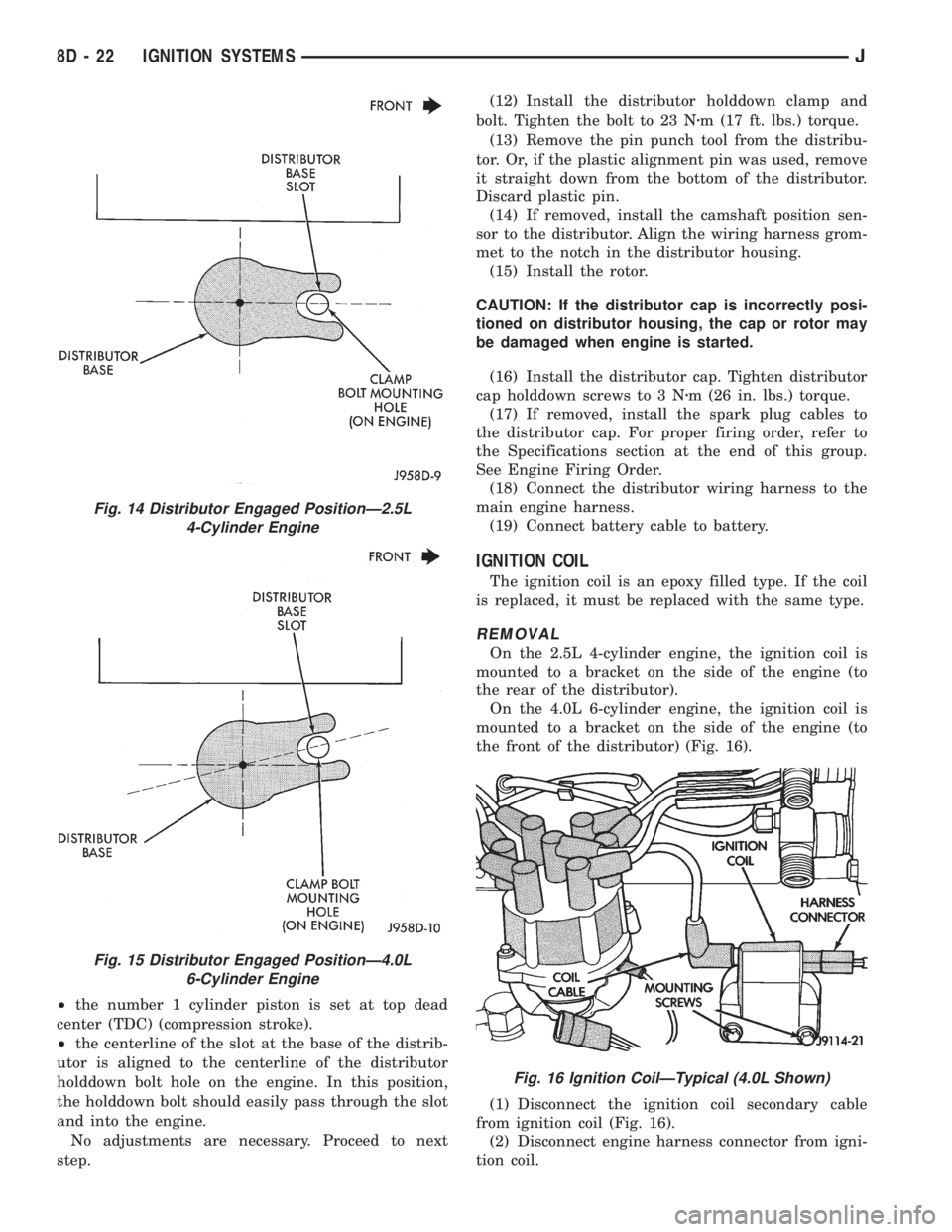
²the number 1 cylinder piston is set at top dead
center (TDC) (compression stroke).
²the centerline of the slot at the base of the distrib-
utor is aligned to the centerline of the distributor
holddown bolt hole on the engine. In this position,
the holddown bolt should easily pass through the slot
and into the engine.
No adjustments are necessary. Proceed to next
step.(12) Install the distributor holddown clamp and
bolt. Tighten the bolt to 23 Nzm (17 ft. lbs.) torque.
(13) Remove the pin punch tool from the distribu-
tor. Or, if the plastic alignment pin was used, remove
it straight down from the bottom of the distributor.
Discard plastic pin.
(14) If removed, install the camshaft position sen-
sor to the distributor. Align the wiring harness grom-
met to the notch in the distributor housing.
(15) Install the rotor.
CAUTION: If the distributor cap is incorrectly posi-
tioned on distributor housing, the cap or rotor may
be damaged when engine is started.
(16) Install the distributor cap. Tighten distributor
cap holddown screws to 3 Nzm (26 in. lbs.) torque.
(17) If removed, install the spark plug cables to
the distributor cap. For proper firing order, refer to
the Specifications section at the end of this group.
See Engine Firing Order.
(18) Connect the distributor wiring harness to the
main engine harness.
(19) Connect battery cable to battery.
IGNITION COIL
The ignition coil is an epoxy filled type. If the coil
is replaced, it must be replaced with the same type.
REMOVAL
On the 2.5L 4-cylinder engine, the ignition coil is
mounted to a bracket on the side of the engine (to
the rear of the distributor).
On the 4.0L 6-cylinder engine, the ignition coil is
mounted to a bracket on the side of the engine (to
the front of the distributor) (Fig. 16).
(1) Disconnect the ignition coil secondary cable
from ignition coil (Fig. 16).
(2) Disconnect engine harness connector from igni-
tion coil.
Fig. 14 Distributor Engaged PositionÐ2.5L
4-Cylinder Engine
Fig. 15 Distributor Engaged PositionÐ4.0L
6-Cylinder Engine
Fig. 16 Ignition CoilÐTypical (4.0L Shown)
8D - 22 IGNITION SYSTEMSJ
Page 1121 of 2198

at the engine cylinder head. Also tap the top of the
retainer to seat the valve locks.
(8) Install the engine cylinder head.
VALVE TIMING
Disconnect the spark plug wires and remove the
spark plugs.
Remove the engine cylinder head cover.
Remove the capscrews, bridge and pivot assembly,
and rocker arms from above the No.1 cylinder.
Alternately loosen each capscrew, one turn at a
time, to avoid damaging the bridge.
Rotate the crankshaft until the No.4 piston is at
top dead center (TDC) on the compression stroke.
Rotate the crankshaft counterclockwise (viewed
from the front of the engine) 90É.
Install a dial indicator on the end of the No.1 cyl-
inder intake valve push rod. Use rubber tubing to se-
cure the indicator stem on the push rod.
Set the dial indicator pointer at zero.
Rotate the crankshaft clockwise (viewed from the
front of the engine) until the dial indicator pointer
indicates 0.305 mm (0.012 inch) travel distance (lift).
The timing notch index on the vibration damper
should be aligned with the TDC mark on the timing
degree scale.
If the timing notch is more than 13 mm (1/2 inch)
away from the TDC mark in either direction, the
valve timing is incorrect.
If the valve timing is incorrect, the cause may be a
broken camshaft pin. It is not necessary to replace
the camshaft because of pin failure. A spring pin is
available for service replacement.
VIBRATION DAMPER
REMOVAL
(1) Disconnect negative cable from battery.
(2) Remove the serpentine drive belt and fan
shroud.
(3) Remove the vibration damper retaining bolt
and washer.
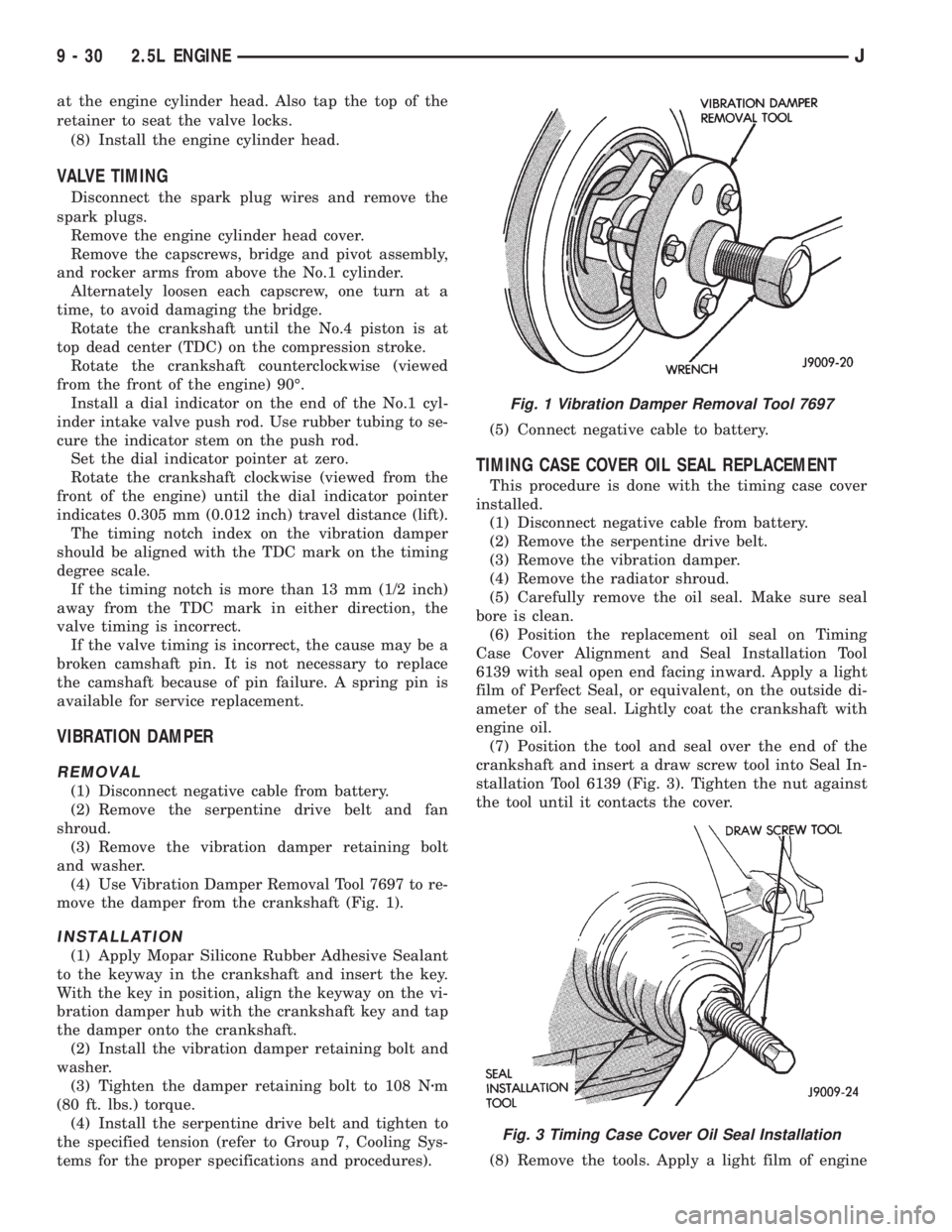
(4) Use Vibration Damper Removal Tool 7697 to re-
move the damper from the crankshaft (Fig. 1).
INSTALLATION
(1) Apply Mopar Silicone Rubber Adhesive Sealant
to the keyway in the crankshaft and insert the key.
With the key in position, align the keyway on the vi-
bration damper hub with the crankshaft key and tap
the damper onto the crankshaft.
(2) Install the vibration damper retaining bolt and
washer.
(3) Tighten the damper retaining bolt to 108 Nzm
(80 ft. lbs.) torque.
(4) Install the serpentine drive belt and tighten to
the specified tension (refer to Group 7, Cooling Sys-
tems for the proper specifications and procedures).(5) Connect negative cable to battery.
TIMING CASE COVER OIL SEAL REPLACEMENT
This procedure is done with the timing case cover
installed.
(1) Disconnect negative cable from battery.
(2) Remove the serpentine drive belt.
(3) Remove the vibration damper.
(4) Remove the radiator shroud.
(5) Carefully remove the oil seal. Make sure seal
bore is clean.
(6) Position the replacement oil seal on Timing
Case Cover Alignment and Seal Installation Tool
6139 with seal open end facing inward. Apply a light
film of Perfect Seal, or equivalent, on the outside di-
ameter of the seal. Lightly coat the crankshaft with
engine oil.
(7) Position the tool and seal over the end of the
crankshaft and insert a draw screw tool into Seal In-
stallation Tool 6139 (Fig. 3). Tighten the nut against
the tool until it contacts the cover.
(8) Remove the tools. Apply a light film of engine
Fig. 1 Vibration Damper Removal Tool 7697
Fig. 3 Timing Case Cover Oil Seal Installation
9 - 30 2.5L ENGINEJ