1995 JEEP CHEROKEE fuel tank removal
[x] Cancel search: fuel tank removalPage 261 of 2198
nostic Procedures manual for diagnostic information
and operation of the DRB scan tool.
To test operation of the fan relay only, refer to Re-
laysÐOperation/Testing. This can be found in Group
14, Fuel Systems.
REMOVAL
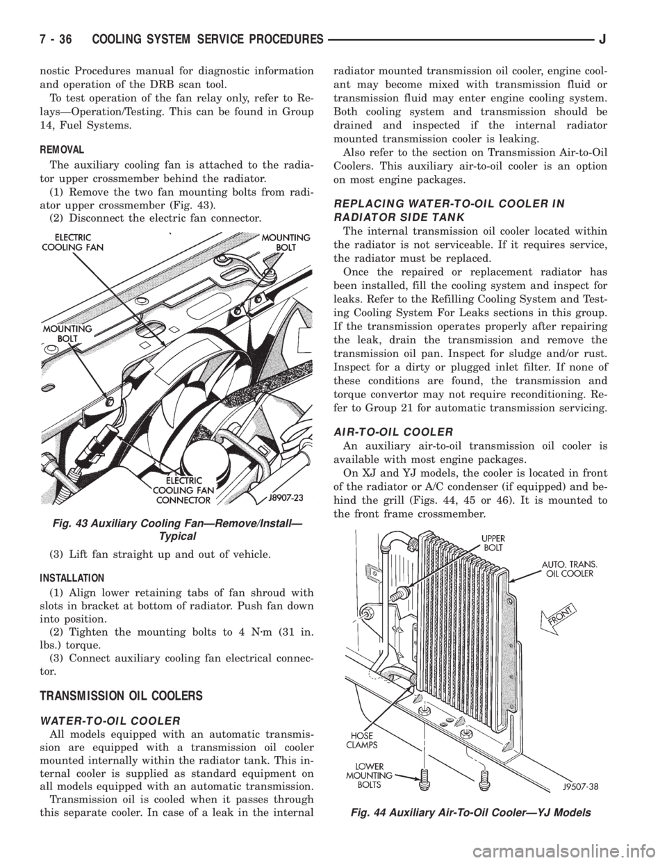
The auxiliary cooling fan is attached to the radia-
tor upper crossmember behind the radiator.
(1) Remove the two fan mounting bolts from radi-
ator upper crossmember (Fig. 43).
(2) Disconnect the electric fan connector.
(3) Lift fan straight up and out of vehicle.
INSTALLATION
(1) Align lower retaining tabs of fan shroud with
slots in bracket at bottom of radiator. Push fan down
into position.
(2) Tighten the mounting bolts to 4 Nzm (31 in.
lbs.) torque.
(3) Connect auxiliary cooling fan electrical connec-
tor.
TRANSMISSION OIL COOLERS
WATER-TO-OIL COOLER
All models equipped with an automatic transmis-
sion are equipped with a transmission oil cooler
mounted internally within the radiator tank. This in-
ternal cooler is supplied as standard equipment on
all models equipped with an automatic transmission.
Transmission oil is cooled when it passes through
this separate cooler. In case of a leak in the internalradiator mounted transmission oil cooler, engine cool-
ant may become mixed with transmission fluid or
transmission fluid may enter engine cooling system.
Both cooling system and transmission should be
drained and inspected if the internal radiator
mounted transmission cooler is leaking.
Also refer to the section on Transmission Air-to-Oil
Coolers. This auxiliary air-to-oil cooler is an option
on most engine packages.
REPLACING WATER-TO-OIL COOLER IN
RADIATOR SIDE TANK
The internal transmission oil cooler located within
the radiator is not serviceable. If it requires service,
the radiator must be replaced.
Once the repaired or replacement radiator has
been installed, fill the cooling system and inspect for
leaks. Refer to the Refilling Cooling System and Test-
ing Cooling System For Leaks sections in this group.
If the transmission operates properly after repairing
the leak, drain the transmission and remove the
transmission oil pan. Inspect for sludge and/or rust.
Inspect for a dirty or plugged inlet filter. If none of
these conditions are found, the transmission and
torque convertor may not require reconditioning. Re-
fer to Group 21 for automatic transmission servicing.
AIR-TO-OIL COOLER
An auxiliary air-to-oil transmission oil cooler is
available with most engine packages.
On XJ and YJ models, the cooler is located in front
of the radiator or A/C condenser (if equipped) and be-
hind the grill (Figs. 44, 45 or 46). It is mounted to
the front frame crossmember.
Fig. 43 Auxiliary Cooling FanÐRemove/InstallÐ
Typical
Fig. 44 Auxiliary Air-To-Oil CoolerÐYJ Models
7 - 36 COOLING SYSTEM SERVICE PROCEDURESJ
Page 322 of 2198
(4) Crank the engine for 5 seconds while monitor-
ing the voltage at the coil positive terminal:
²If the voltage remains near zero during the entire
period of cranking, refer to On-Board Diagnostics in
Group 14, Fuel Systems. Check the powertrain con-
trol module (PCM) and auto shutdown relay.
²If voltage is at or near battery voltage and drops
to zero after 1-2 seconds of cranking, check the cam-
shaft position sensor-to-PCM circuit. Refer to On-
Board Diagnostics in Group 14, Fuel Systems.
²If voltage remains at or near battery voltage dur-
ing the entire 5 seconds, turn the key off. Remove
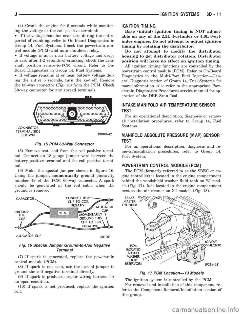
the 60-way connector (Fig. 15) from the PCM. Check
60-way connector for any spread terminals.
(5) Remove test lead from the coil positive termi-
nal. Connect an 18 gauge jumper wire between the
battery positive terminal and the coil positive termi-
nal.
(6) Make the special jumper shown in figure 16.
Using the jumper,momentarilyground pin/cavity
number 19 of the PCM 60-way connector. A spark
should be generated at the coil cable when the
ground is removed.
(7) If spark is generated, replace the powertrain
control module (PCM).
(8) If spark is not seen, use the special jumper to
ground the coil negative terminal directly.
(9) If spark is produced, repair wiring harness for
an open condition.
(10) If spark is not produced, replace the ignition
coil.IGNITION TIMING
Base (initial) ignition timing is NOT adjust-
able on any of the 2.5L 4-cylinder or 4.0L 6-cyl-
inder engines. Do not attempt to adjust ignition
timing by rotating the distributor.
Do not attempt to modify the distributor
housing to get distributor rotation. Distributor
position will have no effect on ignition timing.
All ignition timing functions are controlled by the
powertrain control module (PCM). Refer to On-Board
Diagnostics in the Multi-Port Fuel InjectionÐGen-
eral Diagnosis section of Group 14, Fuel Systems for
more information. Also refer to the appropriate Pow-
ertrain Diagnostics Procedures service manual for op-
eration of the DRB Scan Tool.
INTAKE MANIFOLD AIR TEMPERATURE SENSOR
TEST
For an operational description, diagnosis or remov-
al/ installation procedures, refer to Group 14, Fuel
Systems.
MANIFOLD ABSOLUTE PRESSURE (MAP) SENSOR
TEST
For an operational description, diagnosis and re-
moval/installation procedures, refer to Group 14,
Fuel System.
POWERTRAIN CONTROL MODULE (PCM)
The PCM (formerly referred to as the SBEC or en-
gine controller) is located in the engine compartment
behind the windshield washer fluid tank on YJ mod-
els (Fig. 17). It is located in the engine compartment
next to the air cleaner on XJ models (Fig. 18).
The ignition system is controlled by the PCM.
For removal and installation of this component, re-
fer to the Component Removal/Installation section of
this group.
Fig. 15 PCM 60-Way Connector
Fig. 16 Special Jumper Ground-to-Coil Negative
Terminal
Fig. 17 PCM LocationÐYJ Models
JIGNITION SYSTEMS 8D - 11
Page 454 of 2198
(6) Fuel tank should be FULL. Add 2.94 kg (6.5
lbs.) of weight over the fuel tank for each estimated
gallon of missing fuel.
HEADLAMP/FOG LAMP ADJUSTMENT USING
ALIGNMENT SCREENÐXJ
ALIGNMENT SCREEN PREPARATION
(1) Position vehicle on a level surface perpendicu-
lar to a flat wall 7.62 meters (25 ft) away from front
of headlamp lens (Fig. 1).
(2) If necessary, tape a line on the floor 7.62
meters (25 ft) away from and parallel to the wall.
(3) Measure from the floor up 1.27 meters (5 ft)
and tape a line on the wall at the centerline of the
vehicle. Sight along the centerline of the vehicle
(from rear of vehicle forward) to verify accuracy of
the line placement.
(4) Rock vehicle side-to-side three times to allow
suspension to stabilize.
(5) Jounce front suspension three times by pushing
downward on front bumper and releasing.
(6) Measure the distance from the center of head-
lamp lens to the floor. Transfer measurement to the
alignment screen (with tape). Use this line for up/
down adjustment reference.
(7) Measure distance from the centerline of the ve-
hicle to the center of each headlamp being aligned.
Transfer measurements to screen (with tape) to each
side of vehicle centerline. Use these lines for left/
right adjustment reference.
ADJUSTMENT
(1) Remove screws and both headlamp bezels.
(2) Clean front of the headlamps.
(3) Place headlamps on LOW beam.
(4) Cover front of the headlamp that is not being
adjusted.
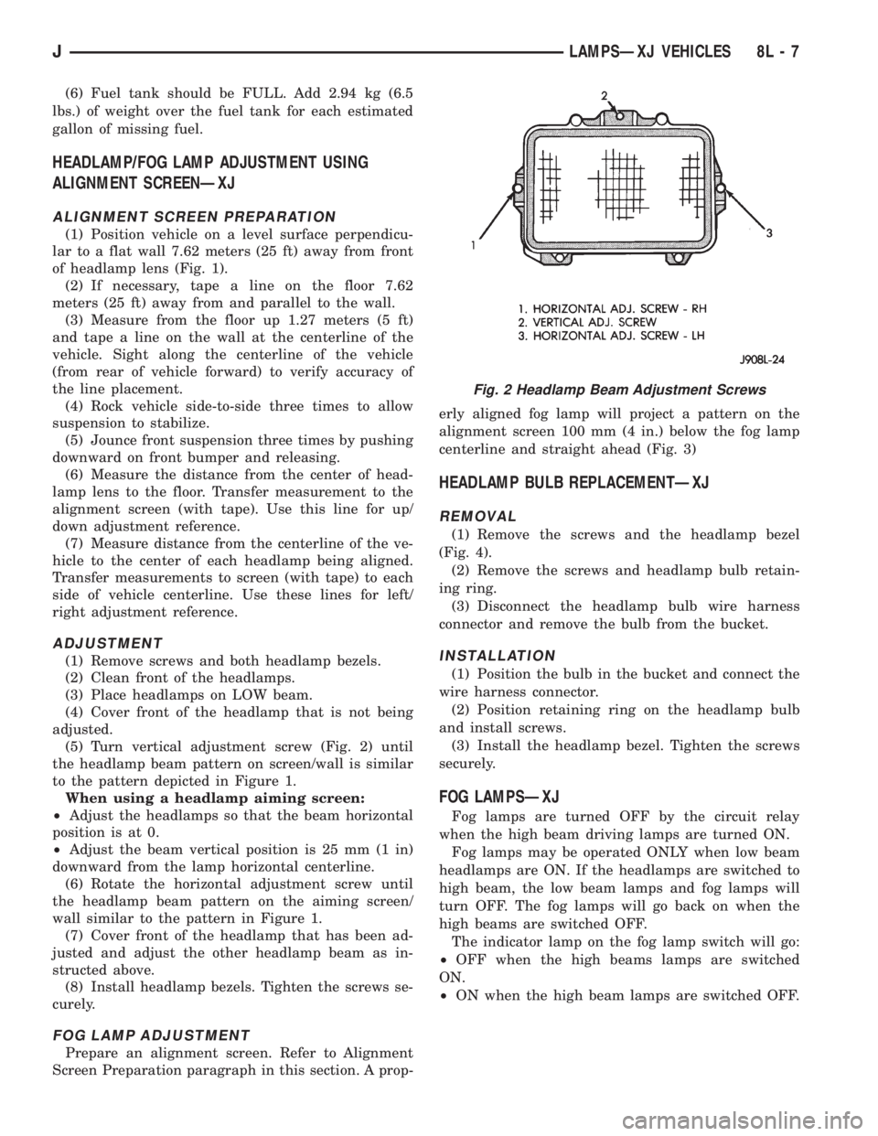
(5) Turn vertical adjustment screw (Fig. 2) until
the headlamp beam pattern on screen/wall is similar
to the pattern depicted in Figure 1.
When using a headlamp aiming screen:
²Adjust the headlamps so that the beam horizontal
position is at 0.
²Adjust the beam vertical position is 25 mm (1 in)
downward from the lamp horizontal centerline.
(6) Rotate the horizontal adjustment screw until
the headlamp beam pattern on the aiming screen/
wall similar to the pattern in Figure 1.
(7) Cover front of the headlamp that has been ad-
justed and adjust the other headlamp beam as in-
structed above.
(8) Install headlamp bezels. Tighten the screws se-
curely.
FOG LAMP ADJUSTMENT
Prepare an alignment screen. Refer to Alignment
Screen Preparation paragraph in this section. A prop-erly aligned fog lamp will project a pattern on the
alignment screen 100 mm (4 in.) below the fog lamp
centerline and straight ahead (Fig. 3)
HEADLAMP BULB REPLACEMENTÐXJ
REMOVAL
(1) Remove the screws and the headlamp bezel
(Fig. 4).
(2) Remove the screws and headlamp bulb retain-
ing ring.
(3) Disconnect the headlamp bulb wire harness
connector and remove the bulb from the bucket.
INSTALLATION
(1) Position the bulb in the bucket and connect the
wire harness connector.
(2) Position retaining ring on the headlamp bulb
and install screws.
(3) Install the headlamp bezel. Tighten the screws
securely.
FOG LAMPSÐXJ
Fog lamps are turned OFF by the circuit relay
when the high beam driving lamps are turned ON.
Fog lamps may be operated ONLY when low beam
headlamps are ON. If the headlamps are switched to
high beam, the low beam lamps and fog lamps will
turn OFF. The fog lamps will go back on when the
high beams are switched OFF.
The indicator lamp on the fog lamp switch will go:
²OFF when the high beams lamps are switched
ON.
²ON when the high beam lamps are switched OFF.
Fig. 2 Headlamp Beam Adjustment Screws
JLAMPSÐXJ VEHICLES 8L - 7
Page 1194 of 2198
INSTALLATION
(1) Install the muffler onto the catalytic converter
outlet. Ensure that the locator on the converter
aligns with the notch on the muffler, if so equipped.
Install the clamp and tighten the nuts finger tight.
(2) Install the exhaust tailpipe into the muffler
outlet. Ensure that the locator on the exhaust
tailpipe aligns with the notch on the muffler, if so
equipped. Install the clamp and tighten the nuts fin-
ger tight.
(3) Install the front exhaust tailpipe supports and
the rear exhaust tailpipe hanger. Ensure that the ex-
haust tailpipe has sufficient clearance from the floor
pan and shields.
(4) Tighten the nuts on the muffler-to-catalytic
converter and the muffler-to-exhaust tailpipe clamps
to 61 Nzm (45 ft. lbs.) torque.
(5) Lower the vehicle.
(6) Start the engine and inspect for exhaust leaks
and contact with the body panels and shields.
ENGINE EXHAUST MANIFOLDÐ2.5L ENGINE
REMOVAL
(1) Disconnect the battery negative cable.
(2) Remove all components attached to the intake
manifold.
(3) Raise the vehicle.
(4) Disconnect the exhaust pipe from the engine
exhaust manifold.
(5) Lower the vehicle.
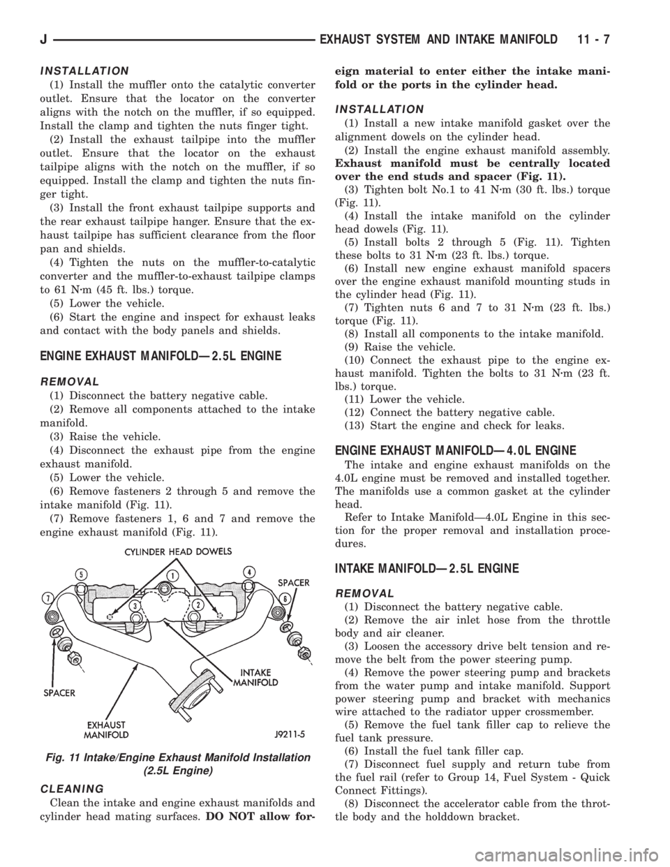
(6) Remove fasteners 2 through 5 and remove the
intake manifold (Fig. 11).
(7) Remove fasteners 1, 6 and 7 and remove the
engine exhaust manifold (Fig. 11).
CLEANING
Clean the intake and engine exhaust manifolds and
cylinder head mating surfaces.DO NOT allow for-eign material to enter either the intake mani-
fold or the ports in the cylinder head.
INSTALLATION
(1) Install a new intake manifold gasket over the
alignment dowels on the cylinder head.
(2) Install the engine exhaust manifold assembly.
Exhaust manifold must be centrally located
over the end studs and spacer (Fig. 11).
(3) Tighten bolt No.1 to 41 Nzm (30 ft. lbs.) torque
(Fig. 11).
(4) Install the intake manifold on the cylinder
head dowels (Fig. 11).
(5) Install bolts 2 through 5 (Fig. 11). Tighten
these bolts to 31 Nzm (23 ft. lbs.) torque.
(6) Install new engine exhaust manifold spacers
over the engine exhaust manifold mounting studs in
the cylinder head (Fig. 11).
(7) Tighten nuts 6 and 7 to 31 Nzm (23 ft. lbs.)
torque (Fig. 11).
(8) Install all components to the intake manifold.
(9) Raise the vehicle.
(10) Connect the exhaust pipe to the engine ex-
haust manifold. Tighten the bolts to 31 Nzm (23 ft.
lbs.) torque.
(11) Lower the vehicle.
(12) Connect the battery negative cable.
(13) Start the engine and check for leaks.
ENGINE EXHAUST MANIFOLDÐ4.0L ENGINE
The intake and engine exhaust manifolds on the
4.0L engine must be removed and installed together.
The manifolds use a common gasket at the cylinder
head.
Refer to Intake ManifoldÐ4.0L Engine in this sec-
tion for the proper removal and installation proce-
dures.
INTAKE MANIFOLDÐ2.5L ENGINE
REMOVAL
(1) Disconnect the battery negative cable.
(2) Remove the air inlet hose from the throttle
body and air cleaner.
(3) Loosen the accessory drive belt tension and re-
move the belt from the power steering pump.
(4) Remove the power steering pump and brackets
from the water pump and intake manifold. Support
power steering pump and bracket with mechanics
wire attached to the radiator upper crossmember.
(5) Remove the fuel tank filler cap to relieve the
fuel tank pressure.
(6) Install the fuel tank filler cap.
(7) Disconnect fuel supply and return tube from
the fuel rail (refer to Group 14, Fuel System - Quick
Connect Fittings).
(8) Disconnect the accelerator cable from the throt-
tle body and the holddown bracket.
Fig. 11 Intake/Engine Exhaust Manifold Installation
(2.5L Engine)
JEXHAUST SYSTEM AND INTAKE MANIFOLD 11 - 7
Page 1198 of 2198
FRAME AND BUMPERS
CONTENTS
page page
BUMPERS.............................. 5
BUMPERS............................. 16FRAME................................. 1
FRAME................................ 10
FRAME
INDEX
page page
Frame Dimensions......................... 1
Front Skid Plate........................... 1
Fuel Filler Hose Splash ShieldÐXJ Vehicles...... 4
Fuel Tank Skid Plate........................ 3Fuel Tank Support Strap..................... 4
General Information........................ 1
Transfer Case Skid Plate.................... 3
GENERAL INFORMATION
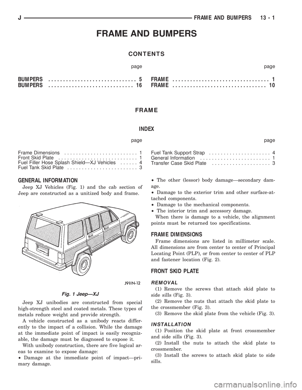
Jeep XJ Vehicles (Fig. 1) and the cab section of
Jeep are constructed as a unitized body and frame.
Jeep XJ unibodies are constructed from special
high-strength steel and coated metals. These types of
metals reduce weight and provide strength.
A vehicle constructed as a unibody reacts differ-
ently to the impact of a collision. While the damage
at the immediate point of impact is easily recogniz-
able, the damage must be diagnosed to expose it.
With unibody construction, there are five logical ar-
eas to examine to expose damage:
²Damage at the immediate point of impactÐpri-
mary damage.²The other (lessor) body damageÐsecondary dam-
age.
²Damage to the exterior trim and other surface-at-
tached components.
²Damage to the mechanical components.
²The interior trim and accessory damage.
When there is damage to a vehicle, the alignment
points must be returned too specifications.
FRAME DIMENSIONS
Frame dimensions are listed in millimeter scale.
All dimensions are from center to center of Principal
Locating Point (PLP), or from center to center of PLP
and fastener location (Fig. 2).
FRONT SKID PLATE
REMOVAL
(1) Remove the screws that attach skid plate to
side sills (Fig. 3).
(2) Remove the nuts that attach the skid plate to
the crossmember (Fig. 3).
(3) Remove the skid plate from the vehicle (Fig. 3).
INSTALLATION
(1) Position the skid plate at front crossmember
and side sills (Fig. 3).
(2) Install the nuts to attach the skid plate to
crossmember.
(3) Install the screws to attach skid plate to side
sills.
Fig. 1 JeepÐXJ
JFRAME AND BUMPERS 13 - 1
Page 1200 of 2198
TRANSFER CASE SKID PLATE
REMOVAL
(1) Support the skid plate.
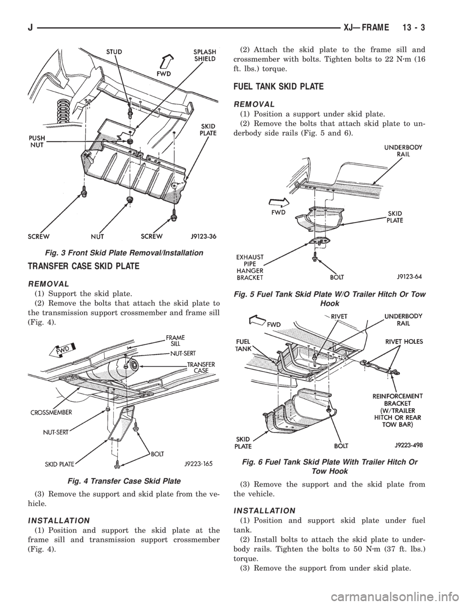
(2) Remove the bolts that attach the skid plate to
the transmission support crossmember and frame sill
(Fig. 4).
(3) Remove the support and skid plate from the ve-
hicle.
INSTALLATION
(1) Position and support the skid plate at the
frame sill and transmission support crossmember
(Fig. 4).(2) Attach the skid plate to the frame sill and
crossmember with bolts. Tighten bolts to 22 Nzm (16
ft. lbs.) torque.
FUEL TANK SKID PLATE
REMOVAL
(1) Position a support under skid plate.
(2) Remove the bolts that attach skid plate to un-
derbody side rails (Fig. 5 and 6).
(3) Remove the support and the skid plate from
the vehicle.
INSTALLATION
(1) Position and support skid plate under fuel
tank.
(2) Install bolts to attach the skid plate to under-
body rails. Tighten the bolts to 50 Nzm (37 ft. lbs.)
torque.
(3) Remove the support from under skid plate.
Fig. 3 Front Skid Plate Removal/Installation
Fig. 4 Transfer Case Skid Plate
Fig. 5 Fuel Tank Skid Plate W/O Trailer Hitch Or Tow
Hook
Fig. 6 Fuel Tank Skid Plate With Trailer Hitch Or
Tow Hook
JXJÐFRAME 13 - 3
Page 1201 of 2198
FUEL FILLER HOSE SPLASH SHIELDÐXJ
VEHICLES
REMOVAL
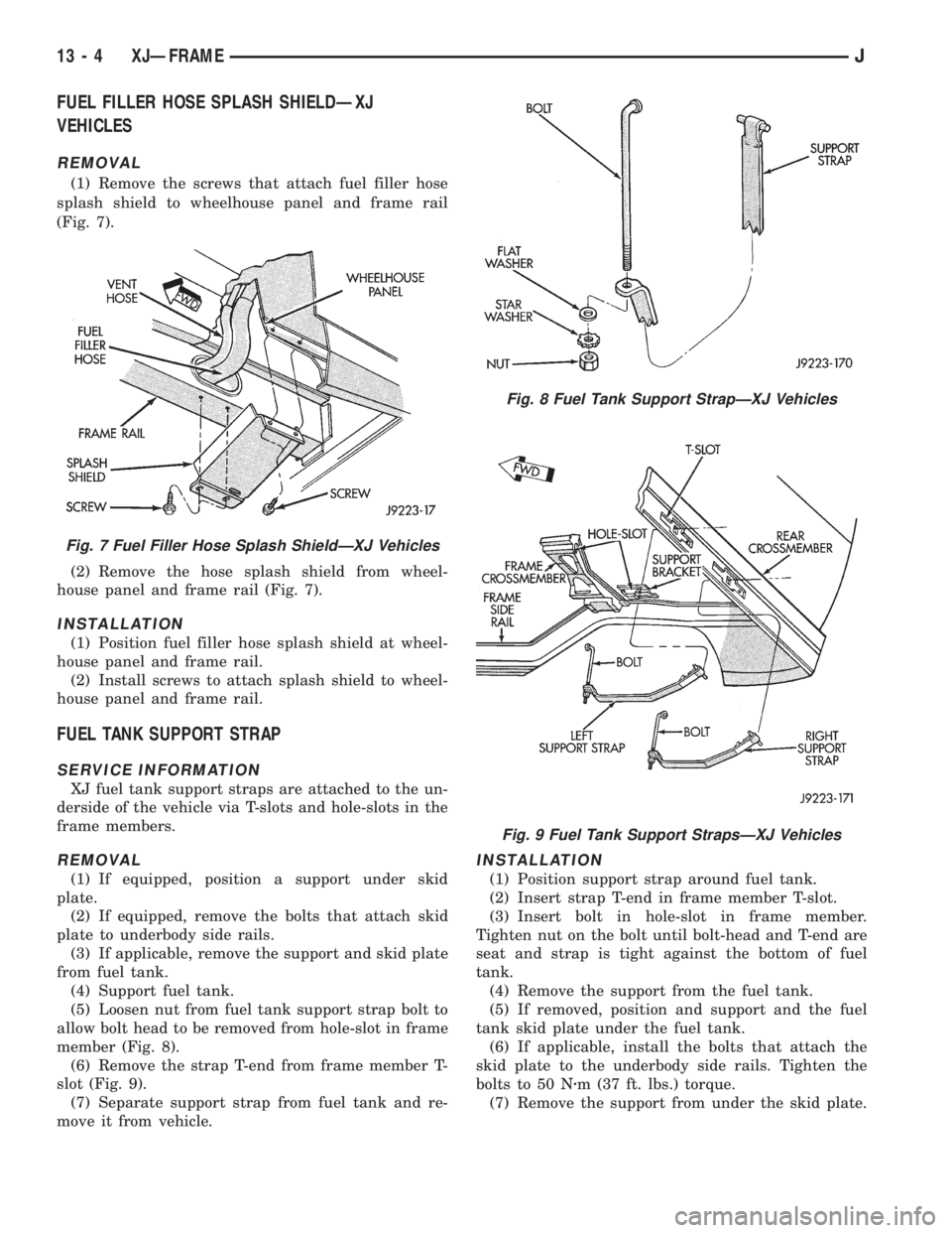
(1) Remove the screws that attach fuel filler hose
splash shield to wheelhouse panel and frame rail
(Fig. 7).
(2) Remove the hose splash shield from wheel-
house panel and frame rail (Fig. 7).
INSTALLATION
(1) Position fuel filler hose splash shield at wheel-
house panel and frame rail.
(2) Install screws to attach splash shield to wheel-
house panel and frame rail.
FUEL TANK SUPPORT STRAP
SERVICE INFORMATION
XJ fuel tank support straps are attached to the un-
derside of the vehicle via T-slots and hole-slots in the
frame members.
REMOVAL
(1) If equipped, position a support under skid
plate.
(2) If equipped, remove the bolts that attach skid
plate to underbody side rails.
(3) If applicable, remove the support and skid plate
from fuel tank.
(4) Support fuel tank.
(5) Loosen nut from fuel tank support strap bolt to
allow bolt head to be removed from hole-slot in frame
member (Fig. 8).
(6) Remove the strap T-end from frame member T-
slot (Fig. 9).
(7) Separate support strap from fuel tank and re-
move it from vehicle.
INSTALLATION
(1) Position support strap around fuel tank.
(2) Insert strap T-end in frame member T-slot.
(3) Insert bolt in hole-slot in frame member.
Tighten nut on the bolt until bolt-head and T-end are
seat and strap is tight against the bottom of fuel
tank.
(4) Remove the support from the fuel tank.
(5) If removed, position and support and the fuel
tank skid plate under the fuel tank.
(6) If applicable, install the bolts that attach the
skid plate to the underbody side rails. Tighten the
bolts to 50 Nzm (37 ft. lbs.) torque.
(7) Remove the support from under the skid plate.
Fig. 7 Fuel Filler Hose Splash ShieldÐXJ Vehicles
Fig. 8 Fuel Tank Support StrapÐXJ Vehicles
Fig. 9 Fuel Tank Support StrapsÐXJ Vehicles
13 - 4 XJÐFRAMEJ
Page 1212 of 2198
INSTALLATION
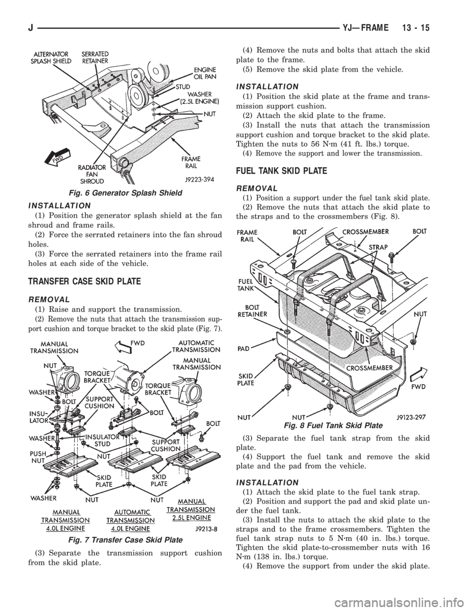
(1) Position the generator splash shield at the fan
shroud and frame rails.
(2) Force the serrated retainers into the fan shroud
holes.
(3) Force the serrated retainers into the frame rail
holes at each side of the vehicle.
TRANSFER CASE SKID PLATE
REMOVAL
(1) Raise and support the transmission.
(2) Remove the nuts that attach the transmission sup-
port cushion and torque bracket to the skid plate (Fig. 7).
(3) Separate the transmission support cushion
from the skid plate.(4) Remove the nuts and bolts that attach the skid
plate to the frame.
(5) Remove the skid plate from the vehicle.
INSTALLATION
(1) Position the skid plate at the frame and trans-
mission support cushion.
(2) Attach the skid plate to the frame.
(3) Install the nuts that attach the transmission
support cushion and torque bracket to the skid plate.
Tighten the nuts to 56 Nzm (41 ft. lbs.) torque.
(4) Remove the support and lower the transmission.
FUEL TANK SKID PLATE
REMOVAL
(1) Position a support under the fuel tank skid plate.
(2) Remove the nuts that attach the skid plate to
the straps and to the crossmembers (Fig. 8).
(3) Separate the fuel tank strap from the skid
plate.
(4) Support the fuel tank and remove the skid
plate and the pad from the vehicle.
INSTALLATION
(1) Attach the skid plate to the fuel tank strap.
(2) Position and support the pad and skid plate un-
der the fuel tank.
(3) Install the nuts to attach the skid plate to the
straps and to the frame crossmembers. Tighten the
fuel tank strap nuts to 5 Nzm (40 in. lbs.) torque.
Tighten the skid plate-to-crossmember nuts with 16
Nzm (138 in. lbs.) torque.
(4) Remove the support from under the skid plate.
Fig. 6 Generator Splash Shield
Fig. 7 Transfer Case Skid Plate
Fig. 8 Fuel Tank Skid Plate
JYJÐFRAME 13 - 15