1995 JEEP CHEROKEE service indicator
[x] Cancel search: service indicatorPage 19 of 2198
USED ENGINE OIL DISPOSAL
Care should be exercised when disposing used en-
gine oil after it has been drained from a vehicle en-
gine. Refer to the WARNING listed above.
ENGINE COOLING SYSTEM
WARNINGS AND PRECAUTIONS
WARNING: ANTIFREEZE IS AN ETHYLENE GLYCOL
BASE COOLANT AND IS HARMFUL IF SWAL-
LOWED OR INHALED. IF SWALLOWED, DRINK
TWO GLASSES OF WATER AND INDUCE VOMIT-
ING. IF INHALED, MOVE TO FRESH AIR AREA.
SEEK MEDICAL ATTENTION IMMEDIATELY. DO NOT
STORE IN OPEN OR UNMARKED CONTAINERS.
WASH SKIN AND CLOTHING THOROUGHLY AFTER
COMING IN CONTACT WITH ETHYLENE GLYCOL.
KEEP OUT OF REACH OF CHILDREN.
DISPOSE OF GLYCOL BASE COOLANT PROP-
ERLY, CONTACT YOUR DEALER OR GOVERNMENT
AGENCY FOR LOCATION OF COLLECTION CENTER
IN YOUR AREA.
DO NOT OPEN A COOLING SYSTEM WHEN THE
ENGINE IS AT RUNNING TEMPERATURE, PER-
SONAL INJURY CAN RESULT.
AVOID RADIATOR COOLING FAN WHEN ENGINE
COMPARTMENT RELATED SERVICE IS PER-
FORMED, PERSONAL INJURY CAN RESULT.
CAUTION: Do not use straight antifreeze as engine
coolant, inadequate engine running temperatures
can result.
Do not operate vehicle without proper concentra-
tion of recommended ethylene glycol coolant, high
running temperatures and cooling system corrosion
can result.
The engine cooling system will develop internal
pressure of 97 to 123 kPa (14 to 18 psi) at normal op-
erating temperature. Allow the vehicle approximately
one half hour to cool off before opening the cooling
system. As an indicator of pressure, squeeze the up-
per radiator hose between index finger and thumb. If
it collapses with little effort the system would have
low internal pressure and should be safe to open to
the first safety notch of the radiator cap. Refer to
Group 7, Cooling System.
COOLING SYSTEM INSPECTION
Coolant level should be inspected when other en-
gine compartment service is performed or when cool-
ant leak is suspected. With the engine at normal
operating temperature, observe the coolant level in
thecoolant recovery bottle. The coolant level mustbe at least above the ADD mark and preferably at
the FULL mark. Add coolant to the coolant recovery
bottleonly, if necessary.
Cooling system freeze protection should be tested
at the onset of the winter season or every 12 months.
Service is required if coolant is low, contaminated,
rusty or freeze protection is inadequate. To properly
test cooling system, see Group 7, Cooling System.
The cooling system factory fill is a mixture of 50%
Ethylene Glycol based antifreeze and 50% water. Us-
ing a suitable hydrometer, measure antifreeze con-
centration in the radiator when the engine is cool. If
the cooling system has recently been serviced, allow
coolant to circulate for at least 20 minutes before
taking hydrometer reading. Properly mixed coolant
will protect the cooling system to -37ÉC (-35ÉF). If the
freeze protection is above -28ÉC (-20ÉF), drain enough
coolant from the cooling system to allow room to add
antifreeze to achieve adequate protection. A mix table
on the coolant container indicates the amount of an-
tifreeze required to winterize the cooling system
based on the capacity, see Capacity Chart in General
Information section of this group.
ANTIFREEZE SPECIFICATION
Chrysler Corporation recommends the use of Mo-
par Antifreeze/Coolant or a high quality, ethylene
glycol base antifreeze/coolant, with a silicate inhibi-
tor.
COOLING SYSTEM SERVICE
The cooling system should be drained, flushed and
filled with the proper coolant mixture at the inter-
vals described in the Lubrication and Maintenance
Schedules. Refer to General Information section of
this group. For proper service instructions see Group
7, Cooling System.
AIR CLEANER ELEMENT
The air cleaner element should be serviced at the
intervals described in the Lubrication and Mainte-
nance Schedules sections of this group. Additional in-
formation can be found in Group 14, Fuel System
and Group 25, Emission System. Inspect all air
cleaner hoses or tubes for damage or leaks when
other engine compartment service is performed. Re-
place faulty components.
FILTER ELEMENT SERVICE/REPLACEMENT
CAUTION: The air cleaner cover must be installed
properly for the emissions system and engine con-
troller to function correctly.
Do not immerse paper air filter element in clean-
ing solvents, damage can result.
(1) Remove the air cleaner cover from the body/
housing (Fig. 9).
0 - 18 LUBRICATION AND MAINTENANCEJ
Page 23 of 2198
DRIVETRAIN
INDEX
page page
Automatic Transmission.................... 23
Clutch and Brake Pedal Bushings............. 22
Clutch Master Cylinder..................... 22
Drive Shafts............................. 26Front and Rear Axles...................... 24
Manual Transmission...................... 22
Rubber and Plastic Hoses/Tubing............. 26
Transfer Case (4WD Vehicles)................ 24
CLUTCH AND BRAKE PEDAL BUSHINGS
If the clutch and brake pedal mechanism squeaks,
the pivot bushings should be lubricated. Use Mopar
Multi-Purpose Lubricant, or an equivalent. Refer to
Group 5, Brakes for location of bushings.
CLUTCH MASTER CYLINDER
LEVEL INSPECTION
WARNING: DO NOT ALLOW PETROLEUM OR WA-
TER BASE LIQUIDS TO CONTAMINATE CLUTCH
FLUID, SEAL DAMAGE AND CLUTCH FAILURE CAN
RESULT.
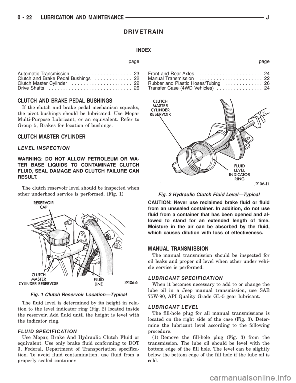
The clutch reservoir level should be inspected when
other underhood service is performed. (Fig. 1)
The fluid level is determined by its height in rela-
tion to the level indicator ring (Fig. 2) located inside
the reservoir. Add fluid until the height is level with
the indicator ring.
FLUID SPECIFICATION
Use Mopar, Brake And Hydraulic Clutch Fluid or
equivalent. Use only brake fluid conforming to DOT
3, Federal, Department of Transportation specifica-
tion. To avoid fluid contamination, use fluid from a
properly sealed container.CAUTION: Never use reclaimed brake fluid or fluid
from an unsealed container. In addition, do not use
fluid from a container that has been opened and al-
lowed to stand for an extended length of time.
Moisture in the air can be absorbed by the fluid,
which causes dilution with loss of effectiveness.
MANUAL TRANSMISSION
The manual transmission should be inspected for
oil leaks and proper oil level when other under vehi-
cle service is performed.
LUBRICANT SPECIFICATION
When it becomes necessary to add to or change the
lube oil in a Jeep manual transmission, use SAE
75W-90, API Quality Grade GL-5 gear lubricant.
LUBRICANT LEVEL
The fill-hole plug for all manual transmissions is
located on the right side of the case (Fig. 3). Deter-
mine the lubricant level according to the following
procedure.
(1) Remove the fill-hole plug (Fig. 3) from the
transmission. The lube oil should be level with the
bottom edge of the fill hole. The level can be slightly
below the bottom edge of the fill hole if the lube oil is
cold.
Fig. 1 Clutch Reservoir LocationÐTypical
Fig. 2 Hydraulic Clutch Fluid LevelÐTypical
0 - 22 LUBRICATION AND MAINTENANCEJ
Page 24 of 2198

If the transmission is warm, lube oil could
drip out of the fill hole. This is acceptable but
the lube oil should not gush out of the fill hole.
(2) If not acceptable, raise the lube oil level to the
bottom edge of the transmission fill hole.
Add lube oil in small amounts to raise the
level.
(3) Install the fill-hole plug in the transmission.
Tighten the plug with 37 Nzm (27 ft. lbs.) torque.
LUBE OIL CHANGE
When it becomes necessary to change manual
transmission lube oil, use the following procedure.
(1) Raise and support the vehicle.
(2) Remove the fill-hole plug from the transmis-
sion.
(3) Place a container to collect the lube oil under
the transmission drain-hole plug.
(4) Remove the drain-hole plug and drain the lube
oil from the transmission into the container.
Care should be exercised when disposing
used lube oil after it has been drained from a
transmission.
(5) Install the drain-hole plug in the transmission.
Tighten the plug with 37 Nzm (27 ft. lbs.) torque.
(6) Fill the transmission until the lube oil begins to
drip out of the fill hole.
(7) Install the fill-hole plug in the transmission.
Tighten the plug with 37 Nzm (27 ft. lbs.) torque.
(8) Remove the support and lower the vehicle.
AUTOMATIC TRANSMISSION
The automatic transmission fluid should be
changed and bands adjusted at the intervals de-
scribed in the Maintenance Schedules section of this
Group. The automatic transmission should be in-
spected for fluid leaks and proper fluid level whenother under hood service is performed. Refer to
Group 21, Transmission for proper service proce-
dures.
CAUTION: To minimize fluid contamination, verify
that dipstick is seated in the fill tube after fluid level
reading is taken.
TO INSPECT THE TRANSMISSION FLUID
LEVEL
WARNING: USE EXTREME CAUTION WHEN THE
ENGINE IS OPERATING. DO NOT PUT YOUR
HANDS NEAR THE DRIVE BELT, PULLEYS OR FAN
BLADE. DO NOT STAND IN A DIRECT LINE WITH
THE FAN BLADE.
(1) Be sure transmission fluid is at normal operat-
ing temperature. Normal operating temperature is
reached after approximately 15 miles (25km) of oper-
ation.
(2) Position the vehicle on a level surface. This is
important for an accurate fluid level check.
(3) While sitting in driver seat, apply brakes and
place gear selector in each position, then move the
selector to:
²XJ vehicles-P (Park).
²YJ vehicles-N (Neutral).
(4) Apply parking brake.
(5) Raise hood and wipe off dipstick handle to pre-
vent dirt from entering fill tube. Then remove trans-
mission fluid level indicator (dipstick) and wipe clean
with a wiping cloth.
(6) Install dipstick and verify it is seated in fill
hole or tube.
(7) Remove dipstick, with handle above tip, take
fluid level reading. If the vehicle has been driven for
at least 15 minutes before inspecting fluid level,
transmission can be considered hot and reading
should be in the OK area. If vehicle has run for less
than 15 minutes and more than 60 seconds transmis-
sion can be considered warm and reading should be
above MIN mark. Add fluid only if level is below
MIN mark on dipstick when transmission is warm
(Fig. 4).
CAUTION: Do not overfill automatic transmission,
leakage or damage can result.
AUTOMATIC TRANSMISSION FLUID
SPECIFICATION
When it becomes necessary to add fluid or when
the ATF is replaced, use:
²MOPAR Dexron IIE/Mercon ATFonlyfor AW-4
automatic transmissions (XJ vehicles).
²MOPAR ATF PLUS type 7176 (YJ vehicles).
Fig. 3 Manual Transmission Fill- & Drain-Hole
PlugsÐTypical
JLUBRICATION AND MAINTENANCE 0 - 23
Page 31 of 2198
FLUID LEVEL
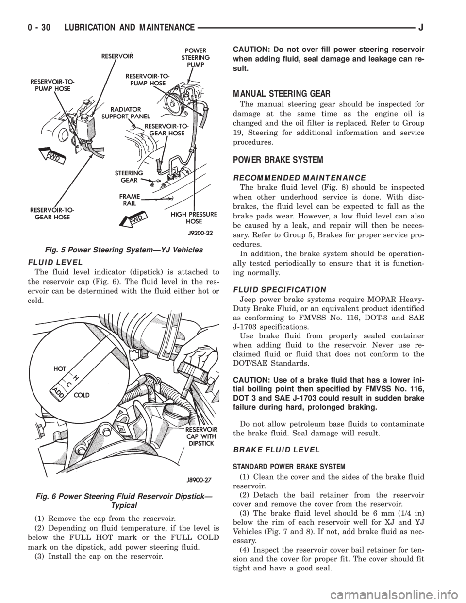
The fluid level indicator (dipstick) is attached to
the reservoir cap (Fig. 6). The fluid level in the res-
ervoir can be determined with the fluid either hot or
cold.
(1) Remove the cap from the reservoir.
(2) Depending on fluid temperature, if the level is
below the FULL HOT mark or the FULL COLD
mark on the dipstick, add power steering fluid.
(3) Install the cap on the reservoir.CAUTION: Do not over fill power steering reservoir
when adding fluid, seal damage and leakage can re-
sult.
MANUAL STEERING GEAR
The manual steering gear should be inspected for
damage at the same time as the engine oil is
changed and the oil filter is replaced. Refer to Group
19, Steering for additional information and service
procedures.
POWER BRAKE SYSTEM
RECOMMENDED MAINTENANCE
The brake fluid level (Fig. 8) should be inspected
when other underhood service is done. With disc-
brakes, the fluid level can be expected to fall as the
brake pads wear. However, a low fluid level can also
be caused by a leak, and repair will then be neces-
sary. Refer to Group 5, Brakes for proper service pro-
cedures.
In addition, the brake system should be operation-
ally tested periodically to ensure that it is function-
ing normally.
FLUID SPECIFICATION
Jeep power brake systems require MOPAR Heavy-
Duty Brake Fluid, or an equivalent product identified
as conforming to FMVSS No. 116, DOT-3 and SAE
J-1703 specifications.
Use brake fluid from properly sealed container
when adding fluid to the reservoir. Never use re-
claimed fluid or fluid that does not conform to the
DOT/SAE Standards.
CAUTION: Use of a brake fluid that has a lower ini-
tial boiling point then specified by FMVSS No. 116,
DOT 3 and SAE J-1703 could result in sudden brake
failure during hard, prolonged braking.
Do not allow petroleum base fluids to contaminate
the brake fluid. Seal damage will result.
BRAKE FLUID LEVEL
STANDARD POWER BRAKE SYSTEM
(1) Clean the cover and the sides of the brake fluid
reservoir.
(2) Detach the bail retainer from the reservoir
cover and remove the cover from the reservoir.
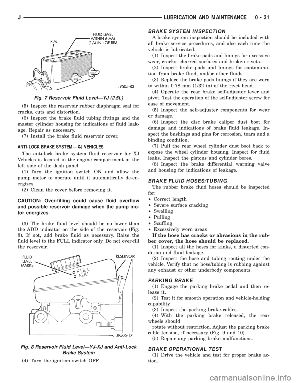
(3) The brake fluid level should be 6 mm (1/4 in)
below the rim of each reservoir well for XJ and YJ
Vehicles (Fig. 7 and 8). If not, add brake fluid as nec-
essary.
(4) Inspect the reservoir cover bail retainer for ten-
sion and the cover for proper fit. The cover should fit
tight and have a good seal.
Fig. 5 Power Steering SystemÐYJ Vehicles
Fig. 6 Power Steering Fluid Reservoir DipstickÐ
Typical
0 - 30 LUBRICATION AND MAINTENANCEJ
Page 32 of 2198
(5) Inspect the reservoir rubber diaphragm seal for
cracks, cuts and distortion.
(6) Inspect the brake fluid tubing fittings and the
master cylinder housing for indications of fluid leak-
age. Repair as necessary.
(7) Install the brake fluid reservoir cover.
ANTI-LOCK BRAKE SYSTEMÐXJ VEHICLES
The anti-lock brake system fluid reservoir for XJ
Vehicles is located in the engine compartment at the
left side of the dash panel.
(1) Turn the ignition switch ON and allow the
pump motor to operate until it automatically de-en-
ergizes.
(2) Clean the cover before removing it.
CAUTION: Over-filling could cause fluid overflow
and possible reservoir damage when the pump mo-
tor energizes.
(3) The brake fluid level should be no lower than
the ADD indicator on the side of the reservoir (Fig.
8). If not, add brake fluid as necessary. Raise the
fluid level to the FULL indicator only. Do not over-fill
the reservoir.
(4) Turn the ignition switch OFF.
BRAKE SYSTEM INSPECTION
A brake system inspection should be included with
all brake service procedures, and also each time the
vehicle is lubricated.
(1) Inspect the brake pads and linings for excessive
wear, cracks, charred surfaces and broken rivets.
(2) Inspect brake pads and linings for contamina-
tion from brake fluid, and/or other fluids.
(3) Replace the brake pads linings if they are worn
to within 0.78 mm (1/32 in) of the rivet head.
(4) Operate the rear brake self-adjuster lever and
pivot. Test the operation of the self-adjuster screw for
ease of movement.
(5) Inspect the self-adjuster components for wear
or damage.
(6) Inspect the disc brake caliper dust boot for
damage and indications of brake fluid leakage. In-
spect the bushings and pins for corrosion, tears and a
binding condition.
(7) Pull the rear wheel cylinder dust boot back to
expose the wheel cylinder housing. Inspect for fluid
leaks. Inspect the pistons and cylinder bores.
(8) Inspect the brake differential warning valve
and housing for indications of leakage.
BRAKE FLUID HOSES/TUBING
The rubber brake fluid hoses should be inspected
for:
²Correct length
²Severe surface cracking
²Swelling
²Pulling
²Scuffing
²Excessively worn areas
If the hose has cracks or abrasions in the rub-
ber cover, the hose should be replaced.
(1) Inspect all the hoses for kinks, a distorted con-
dition and fluid leakage.
(2) Inspect the hose and tubing routing under the
vehicle. Verify that no hose/tubing is rubbing against
any exhaust or other underbody components.
PARKING BRAKE
(1) Engage the parking brake pedal and then re-
lease it.
(2) Test it for smooth operation and vehicle-holding
capability.
(3) Inspect the parking brake cables.
(4) With the parking brake released, the rear
wheels should
rotate without restriction. Adjust the parking brake
cable tension, if necessary (Fig. 9 and 10).
(5) Repair any parking brake malfunctions.
BRAKE OPERATIONAL TEST
(1) Drive the vehicle and test for proper brake ac-
tion.
Fig. 7 Reservoir Fluid LevelÐYJ (2.5L)
Fig. 8 Reservoir Fluid LevelÐYJ-XJ and Anti-Lock
Brake System
JLUBRICATION AND MAINTENANCE 0 - 31
Page 53 of 2198

AXLE NOISE/VIBRATION DIAGNOSIS
INDEX
page page
Driveline Snap........................... 19
Gear and Bearing Noise.................... 18
General Information....................... 18Low Speed Knock......................... 19
Vibration................................ 19
GENERAL INFORMATION
Axle bearing problem conditions are usually caused
by:
²Insufficient or incorrect lubricant
²Foreign matter/water contamination
²Incorrect bearing preload torque adjustment
²Incorrect backlash (to tight)
When serviced, the bearings must be cleaned thor-
oughly. They should be dried with lint-free shop tow-
els.Never dry bearings with compressed air.
This will overheat them and brinell the bearing
surfaces. This will result in noisy operation af-
ter repair.
Axle gear problem conditions are usually the result
of:
²Insufficient lubrication
²Incorrect or contaminated lubricant
²Overloading (excessive engine torque) or exceeding
vehicle weight capacity
²Incorrect clearance or backlash adjustment
Insufficient lubrication is usually the result of a
housing cover leak. It can also be from worn axle
shaft or pinion gear seals. Check for cracks or porous
areas in the housing or tubes.
Using the wrong lubricant will cause overheating
and gear failure. Gear tooth cracking and bearing
spalling are indicators of this.
Axle component breakage is most often the result
of:
²Severe overloading
²Insufficient lubricant
²Incorrect lubricant
²Improperly tightened components
Overloading occurs when towing heavier than rec-
ommended loads. Component breakage can occur
when the wheels are spun excessively. Incorrect lu-
bricant quantity contributes to breakage. Loose dif-
ferential components can also cause breakage.
Incorrect bearing preload or gear backlash will not
result in component breakage. Mis-adjustment will
produce enough noise to cause service repair before a
failure occurs. If a mis-adjustment condition is not
corrected, component failure can result.
Excessive bearing preload may not be noisy. This
condition will cause high temperature which can re-
sult in bearing failure.
GEAR AND BEARING NOISE
GEAR NOISE
Axle gear noise can be caused by insufficient lubri-
cant. Incorrect backlash, tooth contact, or worn/dam-
aged gears can cause noise.
Gear noise usually happens at a specific speed
range. The range is 30 to 40 mph, or above 50 mph.
The noise can also occur during a specific type of
driving condition. These conditions are acceleration,
deceleration, coast, or constant load.
When road testing, accelerate the vehicle to the
speed range where the noise is the greatest. Shift
out-of-gear and coast through the peak-noise range.
If the noise stops or changes greatly, check for insuf-
ficient lubricant. Incorrect ring gear backlash, or
gear damage can cause noise changes.
Differential side and pinion gears can be checked
by turning the vehicle. They usually do not cause
noise in straight-ahead driving. These gears are
loaded during vehicle turns. If noise does occur dur-
ing vehicle turns, the side or pinion gears could be
worn or damaged. A worn pinion gear mate shaft can
also cause a snapping or a knocking noise.
BEARING NOISE
The axle shaft, differential and pinion gear bear-
ings can all produce noise when worn or damaged.
Bearing noise can be either a whining, or a growling
sound.
Pinion gear bearings have a constant-pitch noise.
This noise changes only with vehicle speed. Pinion
bearing noise will be higher because it rotates at a
faster rate. Drive the vehicle and load the differen-
tial. If bearing noise occurs the pinion rear bearing is
the source of the noise. If the bearing noise is heard
during a coast, front bearing is the source.
Worn, damaged differential bearings usually pro-
duce a low pitch noise. Differential bearing noise is
similar to pinion bearing. The pitch of differential
bearing noise is also constant and varies only with
vehicle speed.
2 - 18 FRONT SUSPENSION AND AXLEJ
Page 66 of 2198
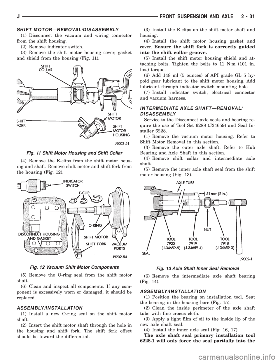
SHIFT MOTORÐREMOVAL/DISASSEMBLY
(1) Disconnect the vacuum and wiring connector
from the shift housing.
(2) Remove indicator switch.
(3) Remove the shift motor housing cover, gasket
and shield from the housing (Fig. 11).
(4) Remove the E-clips from the shift motor hous-
ing and shaft. Remove shift motor and shift fork from
the housing (Fig. 12).
(5) Remove the O-ring seal from the shift motor
shaft.
(6) Clean and inspect all components. If any com-
ponent is excessively worn or damaged, it should be
replaced.
ASSEMBLY/INSTALLATION
(1) Install a new O-ring seal on the shift motor
shaft.
(2) Insert the shift motor shaft through the hole in
the housing and shift fork. The shift fork offset
should be toward the differential.(3) Install the E-clips on the shift motor shaft and
housing.
(4) Install the shift motor housing gasket and
cover.Ensure the shift fork is correctly guided
into the shift collar groove.
(5) Install the shift motor housing shield and at-
taching bolts. Tighten the bolts to 11 Nzm (101 in.
lbs.) torque.
(6) Add 148 ml (5 ounces) of API grade GL 5 hy-
poid gear lubricant to the shift motor housing. Add
lubricant through indicator switch mounting hole.
(7) Install indicator switch, electrical connector
and vacuum harness.
INTERMEDIATE AXLE SHAFTÐREMOVAL/
DISASSEMBLY
Service to the Disconnect axle seals and bearing re-
quire the use of Tool Set 6288 (J34659) and Seal In-
staller 6228.
(1) Remove the vacuum motor housing. Refer to
Shift Motor Removal in this section.
(3) Remove the outer axle shaft. Refer to Hub
Bearing and Axle Shaft in this section.
(4) Remove shift collar and intermediate axle
shaft.
(5) Remove the inner axle shaft seal from the shift
motor housing (Fig. 13).
(6) Remove the intermediate axle shaft bearing
(Fig. 14).
ASSEMBLY/INSTALLATION
(1) Position the bearing on installation tool. Seat
the bearing in the housing bore (Fig. 15).
(2) Clean the inside perimeter of the axle shaft
tube with fine crocus cloth.
(3) Apply a light film of oil to the inside lip of the
new axle shaft seal.
(4) Install the inner axle seal (Fig. 16, 17).
The axle shaft seal primary installation tool
6228-1 will only force the seal partially into the
Fig. 11 Shift Motor Housing and Shift Collar
Fig. 12 Vacuum Shift Motor ComponentsFig. 13 Axle Shaft Inner Seal Removal
JFRONT SUSPENSION AND AXLE 2 - 31
Page 69 of 2198

(4) Install the Hub Bearing and Axle Shaft accord-
ing to the installation procedure.
(5) Reconnect the tie-rod or drag link end onto the
steering knuckle arm. Install the ABS sensor wire
and bracket to the knuckle, refer to Group 5 Brakes.
AXLE BUSHING REPLACEMENT
Refer to Axle Bushing Replacement in the Front
Suspension section.
DIFFERENTIAL REMOVAL
To service the differential the axle assembly and
axle shafts must be removed. Refer to the removal
procedures in this Group.
(1) Note the installation reference letters stamped
on the bearing caps and housing machined sealing
surface (Fig. 22).
(2) Remove the differential bearing caps.
(3) Position Spreader W-129-B with the tool dowel
pins seated in the locating holes (Fig. 23). Install the
holddown clamps and tighten the tool turnbuckle fin-
ger-tight.
(4) Install a pilot stud at the left side of the differ-
ential housing. Attach Dial Indicator to housing pilot
stud. Load the indicator plunger against the opposite
side of the housing (Fig. 23) and zero the indicator.CAUTION:Do not spread over 0.38 mm (0.015 in). If
the housing is over-separated, it could be distorted
or damaged.
(5) Separate the housing enough to remove the
case from the housing. Measure the distance with the
dial indicator (Fig. 23).
(6) Remove the dial indicator.
(7) Pry the differential case loose from the housing.
To prevent damage, pivot on housing with the end of
the pry bar against spreader (Fig. 24).
Fig. 21 Lower Ball Stud Remove/Install
Fig. 22 Bearing Cap Identification
2 - 34 FRONT SUSPENSION AND AXLEJ