1995 JEEP CHEROKEE service indicator
[x] Cancel search: service indicatorPage 368 of 2198
The gauge needle moves as the movable permanent
magnet aligns itself to the changing magnetic fields
created around it by the electromagnets.
COOLANT TEMPERATURE GAUGE
The coolant temperature gauge gives an indication
of engine coolant temperature. The coolant tempera-
ture sending unit is a thermistor that changes elec-
trical resistance with changes in engine coolant
temperature. High sending unit resistance causes
low coolant temperature readings. Low resistance
causes high coolant temperature readings. Sending
unit resistance values are shown in a chart in Spec-
ifications.
FUEL GAUGE
The fuel gauge gives an indication of the level of
fuel in the fuel tank. The fuel gauge sending unit has
a float attached to a swing-arm in the fuel tank. The
float moves up or down within the fuel tank as fuel
level changes. As the float moves, an electrical con-
tact on the swing-arm wipes across a resistor coil,
which changes sending unit resistance. High sending
unit resistance causes high fuel level readings. Low
resistance causes low fuel level readings. Sending
unit resistance values are shown in a chart in Spec-
ifications.
OIL PRESSURE GAUGE
The oil pressure gauge gives an indication of en-
gine oil pressure. The combination oil pressure send-
ing unit contains a flexible diaphragm. The
diaphragm moves in response to changes in engine
oil pressure. As the diaphragm moves, sending unit
resistance increases or decreases. High resistance on
the gauge side of the sending unit causes high oil
pressure readings. Low resistance causes low oil
pressure readings. Sending unit resistance values are
shown in a chart in Specifications.
SPEEDOMETER/ODOMETER
The speedometer/odometer give an indication of ve-
hicle speed and travel distance. The speedometer re-
ceives a vehicle speed pulse signal from the Vehicle
Speed Sensor (VSS). An electronic integrated circuit
contained within the speedometer reads and analyzes
the pulse signal. It then adjusts the ground path re-
sistance of one electromagnet in the gauge to control
needle movement. It also sends signals to an electric
stepper motor to control movement of the odometer
number rolls. Frequency values for the pulse signal
are shown in a chart in Specifications.
The VSS is mounted to an adapter near the trans-
fer case output shaft. The sensor is driven through
the adapter by a speedometer pinion gear. The
adapter and pinion vary with transmission, axle ratio
and tire size. Refer to Group 21 - Transmission and
Transfer Case for more information.
TACHOMETER
The tachometer gives an indication of engine speed
in Revolutions-Per-Minute (RPM). With the engine
running, the tachometer receives an engine speed
pulse signal from the Powertrain Control Module
(PCM). An electronic integrated circuit contained
within the tachometer reads and analyzes the pulse
signal. It then adjusts the ground path resistance of
one electromagnet in the gauge to control needle
movement. Frequency values for the pulse signal are
shown in a chart in Specifications.
TRIP ODOMETER
The trip odometer is driven by the same electronic
integrated circuit as the speedometer/odometer. How-
ever, by depressing the trip odometer reset knob on
the face of the speedometer, the trip odometer can be
reset to zero. The trip odometer is serviced only as a
part of the speedometer/odometer gauge assembly.
VOLTMETER
The voltmeter is connected in parallel with the bat-
tery. With the ignition switch ON, the voltmeter in-
dicates battery or generator output voltage,
whichever is greater.
INDICATOR LAMPS
All indicator lamps, except the four-wheel drive in-
dicator, are located in the main cluster tell-tale area
above the steering column opening. Each of the
lamps is served by the main cluster printed circuit
and cluster connector. The four-wheel drive indicator
lamp is located in the gauge package cluster and is
served by the gauge package printed circuit and clus-
ter connector.
Up to eleven indicator lamps can be found in the
tell-tale area of the main cluster. These lamps are ar-
ranged in two rows, with six lamps in the upper row
and five lamps in the lower row.
ANTI-LOCK BRAKE SYSTEM LAMP
The Anti-Lock Brake System (ABS) lamp is
switched to ground by the ABS module. The module
lights the lamp when the ignition switch is turned to
the START position as a bulb test. The lamp will
stay on for 3 to 5 seconds after vehicle start-up to in-
dicate a system self-test is in process. If the lamp re-
mains on after start-up, or comes on and stays on
while driving, it may indicate that the ABS module
has detected a system malfunction or that the system
has become inoperative. Refer to Group 5 - Brakes
for more information.
BRAKE WARNING LAMP
The brake warning lamp warns the driver that the
parking brake is applied or that the pressures in the
two halves of the split brake hydraulic system are
unequal. With the ignition switch turned ON, battery
JINSTRUMENT PANEL AND GAUGESÐYJ 8E - 25
Page 375 of 2198
INDICATOR LAMPS
If an individual indicator lamp is inoperative, see
the diagnostic procedure under the heading for that
lamp. If more than one indicator lamp or a combina-
tion of lamps and gauges in the main cluster or the
gauge package cluster is inoperative, see Gauges in
this section for diagnosis.
ANTI-LOCK BRAKE SYSTEM LAMP
The diagnosis found here addresses an inoperative
lamp condition. If the ABS lamp stays on with the ig-
nition switch in the ON position, or comes on and
stays on while driving, refer to Group 5 - Brakes for
diagnosis. If no ABS problem is found, the following
procedure will help locate a short or open in the ABS
lamp circuit.
(1) Disconnect battery negative cable. Remove left
instrument cluster bezel and main cluster assembly.
Disconnect ABS control module connector.
(2) Install a jumper wire between cavity 6 of clus-
ter connector and a good ground. Connect battery
negative cable. Turn ignition switch to ON. Lamp
should light. If OK, remove jumper wire and go to
next step. If not OK, replace bulb.
(3) Turn ignition switch to OFF. Disconnect battery
negative cable and unplug cluster connector. Check
for continuity between cavity 6 of cluster connector
and a good ground. There should be no continuity. If
OK, go to next step. If not OK, repair short circuit as
required.
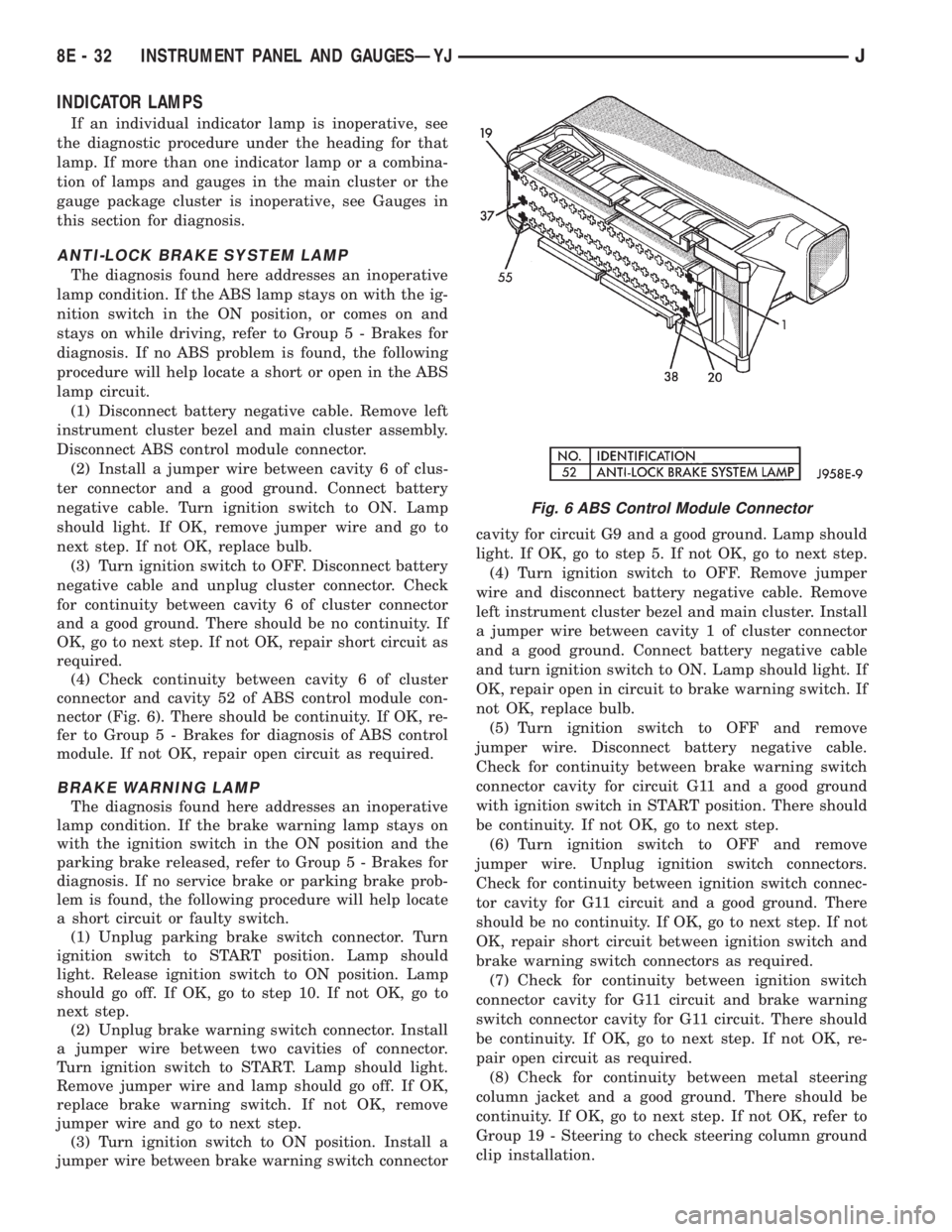
(4) Check continuity between cavity 6 of cluster
connector and cavity 52 of ABS control module con-
nector (Fig. 6). There should be continuity. If OK, re-
fer to Group 5 - Brakes for diagnosis of ABS control
module. If not OK, repair open circuit as required.
BRAKE WARNING LAMP
The diagnosis found here addresses an inoperative
lamp condition. If the brake warning lamp stays on
with the ignition switch in the ON position and the
parking brake released, refer to Group 5 - Brakes for
diagnosis. If no service brake or parking brake prob-
lem is found, the following procedure will help locate
a short circuit or faulty switch.
(1) Unplug parking brake switch connector. Turn
ignition switch to START position. Lamp should
light. Release ignition switch to ON position. Lamp
should go off. If OK, go to step 10. If not OK, go to
next step.
(2) Unplug brake warning switch connector. Install
a jumper wire between two cavities of connector.
Turn ignition switch to START. Lamp should light.
Remove jumper wire and lamp should go off. If OK,
replace brake warning switch. If not OK, remove
jumper wire and go to next step.
(3) Turn ignition switch to ON position. Install a
jumper wire between brake warning switch connectorcavity for circuit G9 and a good ground. Lamp should
light. If OK, go to step 5. If not OK, go to next step.
(4) Turn ignition switch to OFF. Remove jumper
wire and disconnect battery negative cable. Remove
left instrument cluster bezel and main cluster. Install
a jumper wire between cavity 1 of cluster connector
and a good ground. Connect battery negative cable
and turn ignition switch to ON. Lamp should light. If
OK, repair open in circuit to brake warning switch. If
not OK, replace bulb.
(5) Turn ignition switch to OFF and remove
jumper wire. Disconnect battery negative cable.
Check for continuity between brake warning switch
connector cavity for circuit G11 and a good ground
with ignition switch in START position. There should
be continuity. If not OK, go to next step.
(6) Turn ignition switch to OFF and remove
jumper wire. Unplug ignition switch connectors.
Check for continuity between ignition switch connec-
tor cavity for G11 circuit and a good ground. There
should be no continuity. If OK, go to next step. If not
OK, repair short circuit between ignition switch and
brake warning switch connectors as required.
(7) Check for continuity between ignition switch
connector cavity for G11 circuit and brake warning
switch connector cavity for G11 circuit. There should
be continuity. If OK, go to next step. If not OK, re-
pair open circuit as required.
(8) Check for continuity between metal steering
column jacket and a good ground. There should be
continuity. If OK, go to next step. If not OK, refer to
Group 19 - Steering to check steering column ground
clip installation.
Fig. 6 ABS Control Module Connector
8E - 32 INSTRUMENT PANEL AND GAUGESÐYJJ
Page 414 of 2198
TURN SIGNAL AND HAZARD WARNING SYSTEMS
CONTENTS
page page
DIAGNOSIS............................. 3
GENERAL INFORMATION.................. 1SERVICE PROCEDURES................... 5
GENERAL INFORMATION
Following are general descriptions of the major
components in the XJ (Cherokee)/YJ (Wrangler)
model turn signal and hazard warning systems. Refer
to Group 8W - Wiring Diagrams for complete circuit
descriptions and diagrams.
TURN SIGNAL SYSTEM
With the ignition switch in the ON or ACCESSORY
position and the turn signal switch lever (YJ) or
multi-function switch control lever (XJ) moved up
(right turn) or down (left turn), the turn signal sys-
tem is activated.
When the turn signal system is activated, the se-
lected (right or left) turn signal indicator lamp, front
park/turn signal lamp and rear tail/stop/turn signal
lamp bulb filaments will flash. With the headlamp
switch in the OFF position, the turn and front side
marker lamps flash in unison. With the headlamp
switch in the ON position, the turn and front side
marker lamps flash alternately.
HAZARD WARNING SYSTEM
The hazard warning is activated by a switch button
located below the ignition lock cylinder (YJ) or on the
top of the steering column (XJ) between the steering
wheel and the instrument panel. The hazard warning
flasher (YJ) or combination flasher (XJ) receives bat-
tery feed at all times, and the system is functional
regardless of ignition switch position. The hazard
warning switch button is identified with a double
triangle. On YJ models, push the switch button in to
activate the hazard warning system and pull the
button out to turn system off. On XJ models, push in
on the switch button to latch the switch and activate
the hazard warning system, and push in on the
switch button again to unlatch the switch and turn
the system off.
When the hazard warning system is activated, all
(right and left) turn signal indicator, front park/turn
signal lamp and rear tail/stop/turn signal lamp bulb
filaments will flash.
TURN SIGNAL FLASHER (YJ ONLY)
The turn signal flasher is located in the fuseblock
module. It contains one fixed contact point and one
contact point attached to a flexible bimetal arm. The
contact points are normally closed. When a turn sig-
nal is activated, current flows through the flasher. As
current flows through the bimetal arm it heats and
flexes to pull the contact points open, stopping cur-
rent flow. As the bimetal arm cools it straightens,
until the contact points close and the cycle repeats.
The standard flasher is designed to handle the cur-
rent flow requirements of the factory installed light-
ing. If supplemental lighting is added to the turn
signal circuits such as when towing a trailer with
lights, the current flow through the flasher increases.
This causes the flash rate to increase. It is recom-
mended that the standard flasher be replaced with a
heavy-duty (hazard warning) flasher when supple-
mental lighting is added.
However, when a turn signal bulb fails with a stan-
dard flasher, the remaining bulbs in that circuit will
light, but not flash. This will give the driver an indi-
cation to check the turn signal bulbs. Because a
heavy-duty flasher has different internal circuitry, a
failed bulb will not prevent the remaining bulbs in
the circuit from flashing. Therefore, it is recom-
mended that an occasional visual inspection of exte-
rior turn signal lamp operation be performed when a
heavy-duty flasher is installed.
HAZARD WARNING FLASHER (YJ ONLY)
The hazard warning flasher is located in the fuse-
block module. The hazard warning flasher contains
two normally open contact points mounted to two
flexible arms. A bimetal strip is attached between the
two arms. When the hazard warning is activated,
current flows through the flasher. As the current
flows through the bimetal strip it heats and pulls the
flexible arms together until the contact points close,
JTURN SIGNAL AND HAZARD WARNING SYSTEMS 8J - 1
Page 415 of 2198
allowing current flow to the lamps. As the bimetal
strip cools, the contact points are pushed open and
the cycle repeats.
COMBINATION FLASHER (XJ ONLY)
The combination flasher functions as both the turn
signal and hazard warning flasher on XJ models. The
combination flasher is a smart relay that is located in
the relay center under the lower instrument panel
and inboard of the steering column. The combination
flasher can not be repaired. If faulty, it must be
replaced.
The combination flasher is designed to handle the
current flow requirements of the factory installed
lighting. If supplemental lighting is added to the turn
signal circuits such as when towing a trailer with
lights, the combination flasher will automatically
compensate. This allows the flash rate to remain the
same, regardless of electrical load increases. However,
if a bulb fails in the turn signal or hazard warning
circuits, the flash rate of the remaining bulbs in that
circuit will increase to 120 flashes per minute or
higher.
TURN SIGNAL/HAZARD WARNING SWITCH
(YJ ONLY)
The turn signal and hazard warning switches are
combined into a single unit mounted within the upper
steering column bowl and beneath the steering wheel.
The turn signal lever on the left side of the steering
column is moved up or down to select the right or left
turn signal switch position. The turn signals will only
operate with the ignition switch in the ACCESSORY
or ON position.
The hazard warning button on the right side of the
steering column is pushed in to turn the hazard
warning system on, or pulled out to turn the system
off. The hazard warning system will operate regard-
less of ignition switch position. The turn signal/haz-
ard warning switch can not be repaired. If faulty, the
entire unit must be replaced.
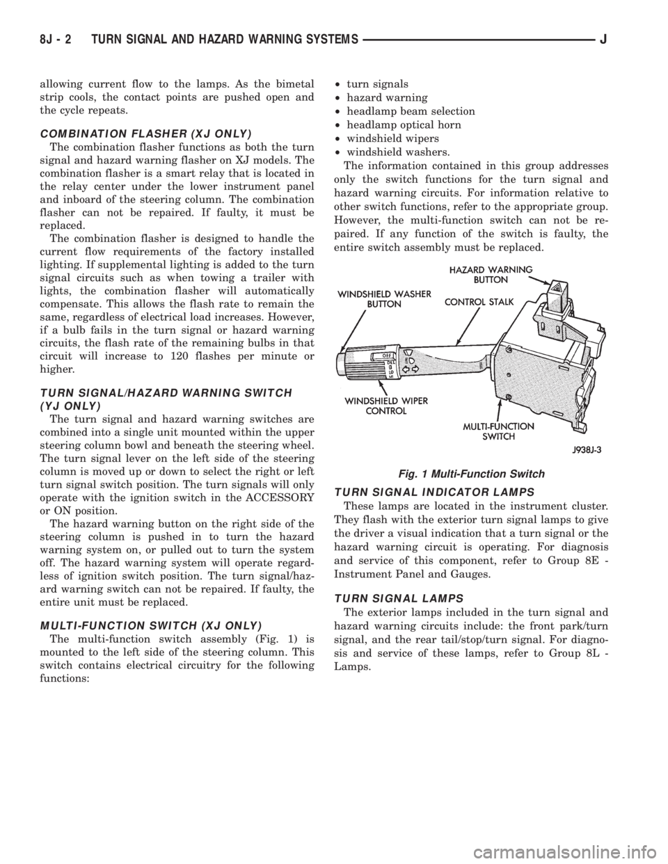
MULTI-FUNCTION SWITCH (XJ ONLY)
The multi-function switch assembly (Fig. 1) is
mounted to the left side of the steering column. This
switch contains electrical circuitry for the following
functions:²turn signals
²hazard warning
²headlamp beam selection
²headlamp optical horn
²windshield wipers
²windshield washers.
The information contained in this group addresses
only the switch functions for the turn signal and
hazard warning circuits. For information relative to
other switch functions, refer to the appropriate group.
However, the multi-function switch can not be re-
paired. If any function of the switch is faulty, the
entire switch assembly must be replaced.
TURN SIGNAL INDICATOR LAMPS
These lamps are located in the instrument cluster.
They flash with the exterior turn signal lamps to give
the driver a visual indication that a turn signal or the
hazard warning circuit is operating. For diagnosis
and service of this component, refer to Group 8E -
Instrument Panel and Gauges.
TURN SIGNAL LAMPS
The exterior lamps included in the turn signal and
hazard warning circuits include: the front park/turn
signal, and the rear tail/stop/turn signal. For diagno-
sis and service of these lamps, refer to Group 8L -
Lamps.
Fig. 1 Multi-Function Switch
8J - 2 TURN SIGNAL AND HAZARD WARNING SYSTEMSJ
Page 416 of 2198
DIAGNOSIS
When diagnosing the turn signal or hazard warning
circuits, remember that high generator output can
burn out bulbs rapidly and repeatedly. If this is a
problem on the vehicle being diagnosed, refer to
Group 8A - Battery/Starting/Charging Systems Diag-
nostics to test charging system.
WARNING: ON VEHICLES EQUIPPED WITH AN AIR-
BAG, REFER TO GROUP 8M - RESTRAINT SYS-
TEMS BEFORE ATTEMPTING STEERING WHEEL
COMPONENT DIAGNOSIS OR SERVICE. FAILURE
TO TAKE PROPER PRECAUTIONS COULD RESULT
IN ACCIDENTAL AIRBAG DEPLOYMENT AND POS-
SIBLE PERSONAL INJURY.
TURN SIGNAL/HAZARD WARNING SYSTEM - XJ
(1) Turn ignition switch to ON position. Actuate the
turn signal lever or hazard warning button. Observe
the turn indicator lamp(s) in the instrument cluster.
If the flash rate is very high, check for a turn signal
bulb that is not lit. Replace that bulb or repair cir-
cuits to that lamp, as required. Test operation. If turn
indicator does not light, continue to next step.
(2) Remove and inspect fuse 8 (turn signals) in
fuseblock module, or fuse F13 (hazard warning) in the
Power Distribution Center. Replace fuse, if required.
(3) Remove combination flasher from relay center
and replace with a known good unit. Test operation of
turn signal and hazard warning systems. If OK, re-place faulty combination flasher. If not OK, remove
test flasher and go to next step.
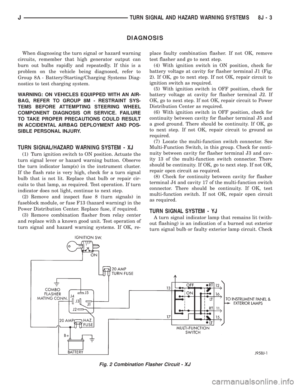
(4) With ignition switch in ON position, check for
battery voltage at cavity for flasher terminal J1 (Fig.
2). If OK, go to next step. If not OK, repair circuit to
ignition switch as required.
(5) With ignition switch in OFF position, check for
battery voltage at cavity for flasher terminal J2. If
OK, go to next step. If not OK, repair circuit to Power
Distribution Center as required.
(6) With ignition switch in OFF position, check for
continuity between cavity for flasher terminal J5 and
a good ground. There should be continuity. If OK, go
to next step. If not OK, repair circuit to ground as
required.
(7) Locate the multi-function switch connector. See
Multi-Function Switch, in this group. Check for conti-
nuity between cavity for flasher terminal J3 and cav-
ity 13 of the multi-function switch connector. There
should be continuity. If OK, go to next step. If not OK,
repair open circuit as required.
(8) Check for continuity between cavity for flasher
terminal J4 and cavity 17 of the multi-function switch
connector. There should be continuity. If OK, test
multi-function switch. If not OK, repair open circuit
as required.
TURN SIGNAL SYSTEM - YJ
A turn signal indicator lamp that remains lit (with-
out flashing) is an indication of a burned out exterior
turn signal bulb or faulty exterior lamp circuit. Check
Fig. 2 Combination Flasher Circuit - XJ
JTURN SIGNAL AND HAZARD WARNING SYSTEMS 8J - 3
Page 453 of 2198
SERVICE PROCEDURES
INDEX
page page
Back-Up/Rear Turn Signal/Tail Lamp Bulb
ReplacementÐXJ....................... 12
Center High Mounted Stop Lamp (CHMSL)ÐXJ . . 12
Daytime Running Lights (Canada Only)ÐXJ..... 15
Drl Module ReplacementÐXJ................ 15
Fog Lamp ReplacementÐXJ.................. 9
Fog Lamp Switch ReplacementÐXJ........... 10
Fog LampsÐXJ........................... 7
Front Park/Turn Signal Lamp Bulb
ReplacementÐXJ........................ 9
Headlamp Alignment PreparationÐXJ........... 6
Headlamp AlignmentÐXJ.................... 6
Headlamp Bulb ReplacementÐXJ.............. 7Headlamp Delay Function Trouble DiagnosisÐXJ . 14
Headlamp Delay Module ReplacementÐXJ...... 14
Headlamp SwitchÐXJ...................... 10
Headlamp/Fog Lamp Adjustment Using Alignment
ScreenÐXJ............................. 7
License Plate LampÐXJ.................... 12
Multi-Function Switch Service ProceduresÐXJ.... 11
Sentinel Headlamp Delay ModuleÐXJ.......... 14
Side Marker Lamp Bulb ReplacementÐXJ....... 10
Underhood Lamp Bulb ReplacementÐXJ....... 13
Underhood Lamp ReplacementÐXJ........... 13
Underhood Lamp Service InformationÐXJ....... 12
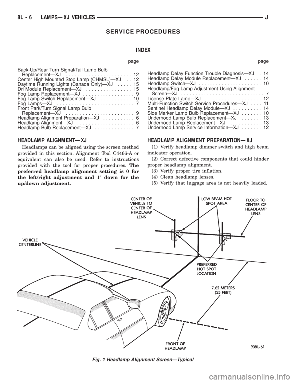
HEADLAMP ALIGNMENTÐXJ
Headlamps can be aligned using the screen method
provided in this section. Alignment Tool C4466-A or
equivalent can also be used. Refer to instructions
provided with the tool for proper procedures.The
preferred headlamp alignment setting is 0 for
the left/right adjustment and 1(down for the
up/down adjustment.
HEADLAMP ALIGNMENT PREPARATIONÐXJ
(1) Verify headlamp dimmer switch and high beam
indicator operation.
(2) Correct defective components that could hinder
proper headlamp alignment.
(3) Verify proper tire inflation.
(4) Clean headlamp lenses.
(5) Verify that luggage area is not heavily loaded.
Fig. 1 Headlamp Alignment ScreenÐTypical
8L - 6 LAMPSÐXJ VEHICLESJ
Page 461 of 2198
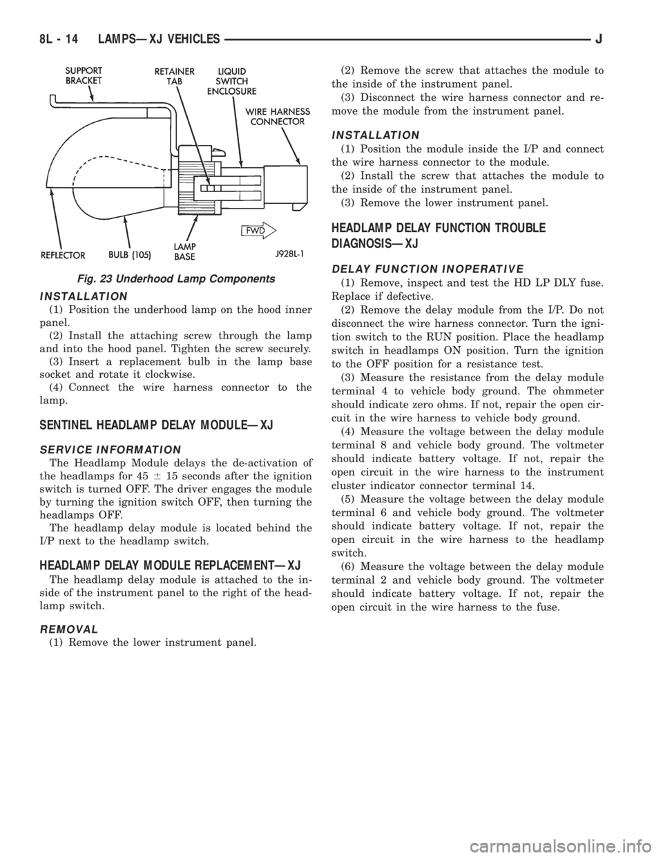
INSTALLATION
(1) Position the underhood lamp on the hood inner
panel.
(2) Install the attaching screw through the lamp
and into the hood panel. Tighten the screw securely.
(3) Insert a replacement bulb in the lamp base
socket and rotate it clockwise.
(4) Connect the wire harness connector to the
lamp.
SENTINEL HEADLAMP DELAY MODULEÐXJ
SERVICE INFORMATION
The Headlamp Module delays the de-activation of
the headlamps for 45615 seconds after the ignition
switch is turned OFF. The driver engages the module
by turning the ignition switch OFF, then turning the
headlamps OFF.
The headlamp delay module is located behind the
I/P next to the headlamp switch.
HEADLAMP DELAY MODULE REPLACEMENTÐXJ
The headlamp delay module is attached to the in-
side of the instrument panel to the right of the head-
lamp switch.
REMOVAL
(1) Remove the lower instrument panel.(2) Remove the screw that attaches the module to
the inside of the instrument panel.
(3) Disconnect the wire harness connector and re-
move the module from the instrument panel.
INSTALLATION
(1) Position the module inside the I/P and connect
the wire harness connector to the module.
(2) Install the screw that attaches the module to
the inside of the instrument panel.
(3) Remove the lower instrument panel.
HEADLAMP DELAY FUNCTION TROUBLE
DIAGNOSISÐXJ
DELAY FUNCTION INOPERATIVE
(1) Remove, inspect and test the HD LP DLY fuse.
Replace if defective.
(2) Remove the delay module from the I/P. Do not
disconnect the wire harness connector. Turn the igni-
tion switch to the RUN position. Place the headlamp
switch in headlamps ON position. Turn the ignition
to the OFF position for a resistance test.
(3) Measure the resistance from the delay module
terminal 4 to vehicle body ground. The ohmmeter
should indicate zero ohms. If not, repair the open cir-
cuit in the wire harness to vehicle body ground.
(4) Measure the voltage between the delay module
terminal 8 and vehicle body ground. The voltmeter
should indicate battery voltage. If not, repair the
open circuit in the wire harness to the instrument
cluster indicator connector terminal 14.
(5) Measure the voltage between the delay module
terminal 6 and vehicle body ground. The voltmeter
should indicate battery voltage. If not, repair the
open circuit in the wire harness to the headlamp
switch.
(6) Measure the voltage between the delay module
terminal 2 and vehicle body ground. The voltmeter
should indicate battery voltage. If not, repair the
open circuit in the wire harness to the fuse.Fig. 23 Underhood Lamp Components
8L - 14 LAMPSÐXJ VEHICLESJ
Page 465 of 2198
BULB APPLICATIONÐXJ VEHICLES
GENERAL INFORMATION
The following Bulb Application Table lists the lamp
title on the left side of the column and trade number
or part number on the right.
CAUTION: Do not use bulbs that have a higher can-
dle power than the bulb listed in the Bulb Applica-
tion Table. Damage to lamp can result.
Do not touch halogen bulbs with fingers or other
oily surfaces. Bulb life will be reduced.
EXTERIOR LAMPSÐXJ
Back-up .................................................................1156
Center High Mounted Stoplamp ..........................922
Fog ............................................................................H3
Front Side Marker .................................................194
Headlamp/Sealed Beam....................................H6054
License Plate ..........................................................168
License Plate W/Outside Spare ..............................67
Park/Turn Signal ............................................2057NA
Tail/Stop ................................................................2057
Turn Signal ...........................................................1156
INTERIOR LAMPSÐXJ
Service procedures for most of the lamps in the in-
strument panel, Instrument cluster and switches are
located in Group 8E, Instrument Panel and Gauges.
Some components have lamps that can only be ser-
viced by an Authorized Service Center (ASC) after
the component is removed from the vehicle. Contact
local dealer for location of nearest ASC.
Cargo .......................................................................561
Dome .......................................................................561
Dome/Reading.........................................................906Glove Compartment ...............................................194
Overhead Console ..................................................912
Under Hood ............................................................105
Vanity Mirror ...........................................................74
Underpanel Courtesy.............................................168
INDICATOR LAMPS
Service procedures for most of the lamps in the in-
strument panel, instrument cluster and switches are
located in Group 8E, Instrument Panel and Gauges.
A/C Control ...............................................................74
Airbag ........................................................................74
Anti-lock Brake ........................................................74
Ash Receiver .........................................................1891
Brake Warning .........................................................74
Check Engine ...........................................................74
Cigar Lighter ............................................................53
Diesel Wait ...............................................................74
Fasten Seat Belts ....................................................74
Four Wheel Drive ....................................................74
Generator ................................................................194
Generator/Diesel.......................................................74
Heater Control .........................................................74
High Beam..............................................................194
Illumination ............................................................194
Low Fuel .................................................................194
Low Washer Fluid....................................................74
Radio ......................................................................ASC
Rocker Switch...........................................................37
Seat Belt ...................................................................74
Transfer Case .........................................................658
Transmission Floor Shift.......................................658
Turn Signal.............................................................194
Shift ...........................................................................74
Water In Fuel ...........................................................74
8L - 18 LAMPSÐXJ VEHICLESJ