1995 JEEP CHEROKEE service indicator
[x] Cancel search: service indicatorPage 76 of 2198
²Axle housing or differential case is replaced
²Pinion select shim pack is unknown
²Ring and pinion gears are replaced
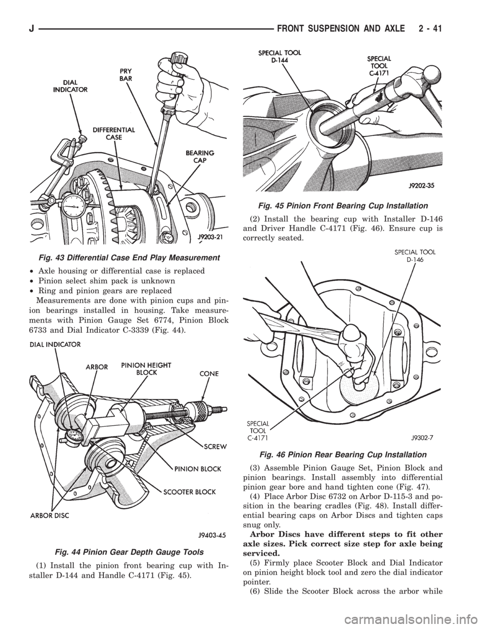
Measurements are done with pinion cups and pin-
ion bearings installed in housing. Take measure-
ments with Pinion Gauge Set 6774, Pinion Block
6733 and Dial Indicator C-3339 (Fig. 44).
(1) Install the pinion front bearing cup with In-
staller D-144 and Handle C-4171 (Fig. 45).(2) Install the bearing cup with Installer D-146
and Driver Handle C-4171 (Fig. 46). Ensure cup is
correctly seated.
(3) Assemble Pinion Gauge Set, Pinion Block and
pinion bearings. Install assembly into differential
pinion gear bore and hand tighten cone (Fig. 47).
(4) Place Arbor Disc 6732 on Arbor D-115-3 and po-
sition in the bearing cradles (Fig. 48). Install differ-
ential bearing caps on Arbor Discs and tighten caps
snug only.
Arbor Discs have different steps to fit other
axle sizes. Pick correct size step for axle being
serviced.
(5) Firmly place Scooter Block and Dial Indicator
on pinion height block tool and zero the dial indicator
pointer.
(6) Slide the Scooter Block across the arbor while
Fig. 43 Differential Case End Play Measurement
Fig. 44 Pinion Gear Depth Gauge Tools
Fig. 45 Pinion Front Bearing Cup Installation
Fig. 46 Pinion Rear Bearing Cup Installation
JFRONT SUSPENSION AND AXLE 2 - 41
Page 94 of 2198
AXLE NOISE/VIBRATION DIAGNOSIS
INDEX
page page
Driveline Snap........................... 10
Gear and Bearing Noise..................... 9
General Information........................ 9
Limited Slip Differential..................... 10Low Speed Knock......................... 10
Rear Axle Alignment....................... 10
Vibration................................ 10
GENERAL INFORMATION
Axle bearing problem conditions are usually caused
by:
²Insufficient or incorrect lubricant
²Foreign matter/water contamination
²Incorrect bearing preload torque adjustment
²Incorrect backlash (to tight)
When serviced, the bearings must be cleaned thor-
oughly. They should be dried with lint-free shop tow-
els.Never dry bearings with compressed air.
This will overheat them and brinell the bearing
surfaces. This will result in noisy operation af-
ter repair.
Axle gear problem conditions are usually the result of:
²Insufficient lubrication
²Incorrect or contaminated lubricant
²Overloading (excessive engine torque) or exceeding
vehicle weight capacity
²Incorrect clearance or backlash adjustment
Insufficient lubrication is usually the result of a
housing cover leak. It can also be from worn axle
shaft or pinion gear seals. Check for cracks or porous
areas in the housing or tubes.
Using the wrong lubricant will cause overheating
and gear failure. Gear tooth cracking and bearing
spalling are indicators of this.
Axle component breakage is most often the result of:
²Severe overloading
²Insufficient lubricant
²Incorrect lubricant
²Improperly tightened components
Overloading occurs when towing heavier than rec-
ommended loads. Component breakage can occur
when the wheels are spun excessively. Incorrect lu-
bricant quantity contributes to breakage. Loose dif-
ferential components can also cause breakage.
Incorrect bearing preload or gear backlash will not
result in component breakage. Mis-adjustment will
produce enough noise to cause service repair before a
failure occurs. If a mis-adjustment condition is not
corrected, component failure can result.
Excessive bearing preload may not be noisy. This
condition will cause high temperature which can re-
sult in bearing failure.
GEAR AND BEARING NOISE
GEAR NOISE
Axle gear noise can be caused by insufficient lubri-
cant. Incorrect backlash, tooth contact, or worn/dam-
aged gears can cause noise.
Gear noise usually happens at a specific speed
range. The range is 30 to 40 mph, or above 50 mph.
The noise can also occur during a specific type of
driving condition. These conditions are acceleration,
deceleration, coast, or constant load.
When road testing, accelerate the vehicle to the
speed range where the noise is the greatest. Shift
out-of-gear and coast through the peak-noise range.
If the noise stops or changes greatly, check for insuf-
ficient lubricant. Incorrect ring gear backlash, or
gear damage can cause noise changes.
Differential side and pinion gears can be checked
by turning the vehicle. They usually do not cause
noise in straight-ahead driving. These gears are
loaded during vehicle turns. If noise does occur dur-
ing vehicle turns, the side or pinion gears could be
worn or damaged. A worn pinion gear mate shaft can
also cause a snapping or a knocking noise.
BEARING NOISE
The axle shaft, differential and pinion gear bear-
ings can all produce noise when worn or damaged.
Bearing noise can be either a whining, or a growling
sound.
Pinion gear bearings have a constant-pitch noise.
This noise changes only with vehicle speed. Pinion
bearing noise will be higher because it rotates at a
faster rate. Drive the vehicle and load the differen-
tial. If bearing noise occurs the pinion rear bearing is
the source of the noise. If the bearing noise is heard
during a coast, front bearing is the source.
Worn, damaged differential bearings usually pro-
duce a low pitch noise. Differential bearing noise is
similar to pinion bearing. The pitch of differential
bearing noise is also constant and varies only with
vehicle speed.
Axle shaft bearings produce noise and vibration
when worn or damaged. The noise generally changes
when the bearings are loaded. Road test the vehicle.
Turn the vehicle sharply to the left and to the right.
JREAR SUSPENSION AND AXLES 3 - 9
Page 103 of 2198
DIFFERENTIAL REMOVAL
To service the differential the axle shafts must be
removed. Refer to the removal procedures in this
Group.
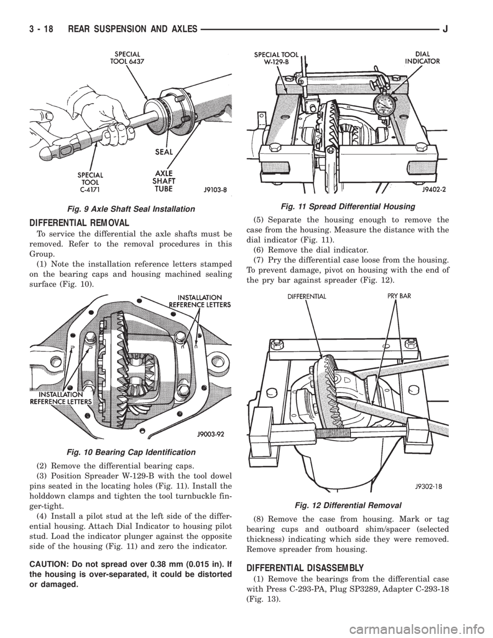
(1) Note the installation reference letters stamped
on the bearing caps and housing machined sealing
surface (Fig. 10).
(2) Remove the differential bearing caps.
(3) Position Spreader W-129-B with the tool dowel
pins seated in the locating holes (Fig. 11). Install the
holddown clamps and tighten the tool turnbuckle fin-
ger-tight.
(4) Install a pilot stud at the left side of the differ-
ential housing. Attach Dial Indicator to housing pilot
stud. Load the indicator plunger against the opposite
side of the housing (Fig. 11) and zero the indicator.
CAUTION: Do not spread over 0.38 mm (0.015 in). If
the housing is over-separated, it could be distorted
or damaged.(5) Separate the housing enough to remove the
case from the housing. Measure the distance with the
dial indicator (Fig. 11).
(6) Remove the dial indicator.
(7) Pry the differential case loose from the housing.
To prevent damage, pivot on housing with the end of
the pry bar against spreader (Fig. 12).
(8) Remove the case from housing. Mark or tag
bearing cups and outboard shim/spacer (selected
thickness) indicating which side they were removed.
Remove spreader from housing.
DIFFERENTIAL DISASSEMBLY
(1) Remove the bearings from the differential case
with Press C-293-PA, Plug SP3289, Adapter C-293-18
(Fig. 13).
Fig. 9 Axle Shaft Seal Installation
Fig. 10 Bearing Cap Identification
Fig. 11 Spread Differential Housing
Fig. 12 Differential Removal
3 - 18 REAR SUSPENSION AND AXLESJ
Page 108 of 2198
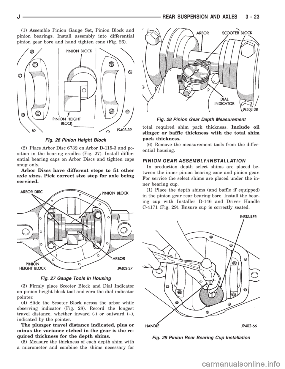
(1) Assemble Pinion Gauge Set, Pinion Block and
pinion bearings. Install assembly into differential
pinion gear bore and hand tighten cone (Fig. 26).
(2) Place Arbor Disc 6732 on Arbor D-115-3 and po-
sition in the bearing cradles (Fig. 27). Install differ-
ential bearing caps on Arbor Discs and tighten caps
snug only.
Arbor Discs have different steps to fit other
axle sizes. Pick correct size step for axle being
serviced.
(3) Firmly place Scooter Block and Dial Indicator
on pinion height block tool and zero the dial indicator
pointer.
(4) Slide the Scooter Block across the arbor while
observing indicator (Fig. 28). Record the longest
travel distance, whether inward (-) or outward (+),
indicated by the pointer.
The plunger travel distance indicated, plus or
minus the variance etched in the gear is the re-
quired thickness for the depth shims.
(5) Measure the thickness of each depth shim with
a micrometer and combine the shims necessary fortotal required shim pack thickness.Include oil
slinger or baffle thickness with the total shim
pack thickness.
(6) Remove the measurement tools from the differ-
ential housing.
PINION GEAR ASSEMBLY/INSTALLATION
In production depth select shims are placed be-
tween the inner pinion bearing cone and pinion gear.
For service the select shims are placed under the in-
ner bearing cup.
(1) Place the depth shims (and baffle if equipped)
in the pinion gear rear bearing bore. Install the bear-
ing cup with Installer D-146 and Driver Handle
C-4171 (Fig. 29). Ensure cup is correctly seated.
Fig. 26 Pinion Height Block
Fig. 27 Gauge Tools In Housing
Fig. 28 Pinion Gear Depth Measurement
Fig. 29 Pinion Rear Bearing Cup Installation
JREAR SUSPENSION AND AXLES 3 - 23
Page 217 of 2198
CLUTCH SERVICE
INDEX
page page
Clutch Component Lubrication................ 10
Clutch Cover and Disc Installation............. 10
Clutch Cover and Disc Removal.............. 10
Clutch Fluid Level......................... 14
Clutch Housing Replacement................ 13
Clutch Hydraulic Linkage Installation........... 14
Clutch Hydraulic Linkage Removal............. 13Clutch Pedal Installation.................... 15
Clutch Pedal Removal...................... 15
Clutch Safety Precautions................... 10
Flywheel Service.......................... 16
Pilot Bearing Replacement.................. 12
Release Bearing Replacement................ 11
CLUTCH SAFETY PRECAUTIONS
WARNING: EXERCISE CARE WHEN SERVICING
CLUTCH COMPONENTS. DUST AND DIRT ON
CLUTCH PARTS USE MAY CONTAIN ASBESTOS FI-
BERS. BREATHING EXCESSIVE CONCENTRATIONS
OF THESE FIBERS CAN CAUSE SERIOUS BODILY
HARM. WEAR A RESPIRATOR DURING SERVICE
AND NEVER CLEAN CLUTCH COMPONENTS WITH
COMPRESSED AIR OR WITH A DRY BRUSH. EI-
THER CLEAN THE COMPONENTS WITH A WATER
DAMPENED RAGS OR USE A VACUUM CLEANER
SPECIFICALLY DESIGNED FOR REMOVING ASBES-
TOS FIBERS AND DUST. DO NOT CREATE DUST BY
SANDING A CLUTCH DISC. REPLACE THE DISC IF
THE FRICTION MATERIAL IS DAMAGED OR CON-
TAMINATED. DISPOSE OF ALL DUST AND DIRT
CONTAINING ASBESTOS FIBERS IN SEALED BAGS
OR CONTAINERS. THIS WILL HELP MINIMIZE EX-
POSURE TO YOURSELF AND TO OTHERS. FOL-
LOW ALL RECOMMENDED SAFETY PRACTICES
PRESCRIBED BY THE OCCUPATIONAL SAFETY
AND HEALTH ADMINISTRATION (OSHA) AND THE
ENVIRONMENTAL SAFETY AGENCY (EPA), FOR
THE HANDLING AND DISPOSAL OF PRODUCTS
CONTAINING ASBESTOS.
CLUTCH COMPONENT LUBRICATION
Proper clutch component lubrication is important
to satisfactory operation. Using the correct lubricant
and not overlubricating are equally important. Apply
recommended lubricant sparingly to avoid disc and
pressure plate contamination.
Clutch and transmission components requiring lu-
brication are:
²pilot bearing
²release lever pivot ball stud
²release lever contact surfaces
²release bearing bore
²clutch disc hub splines
²clutch pedal pivot shaft bore
²clutch pedal bushings²input shaft splines
²input shaft pilot hub
²transmission front bearing retainer slide surface
Never apply grease to any part of the clutch
cover, or disc.
Recommended Lubricants
Use Mopar multi-purpose grease for the clutch
pedal bushings and pivot shaft. Use Mopar high tem-
perature grease (or equivalent) for all other lubrica-
tion requirements. Apply recommended amounts and
do not overlubricate.
CLUTCH COVER AND DISC REMOVAL
(1) Remove transmission. Refer to procedures in
Group 21.
(2) If original clutch cover will be reinstalled, mark
position of cover on flywheel for assembly reference.
Use paint or a scriber for this purpose.
(3) If clutch cover is to be replaced, cover bolts can
be removed in any sequence. However, if original
cover will be reinstalled, loosen cover bolts evenly
and in rotation to relieve spring tension equally. This
is necessary avoid warping cover.
(4) Remove cover bolts and remove cover and disc
(Fig. 2).
CLUTCH COVER AND DISC INSTALLATION
(1) Lightly scuff sand flywheel face with 180 grit
emery cloth. Then clean surface with a wax and
grease remover.
(2) Lubricate pilot bearing with Mopar high tem-
perature bearing grease.
(3) Check runout and free operation of new clutch
disc as follows:
(a) Slide disc onto transmission input shaft
splines. Disc should slide freely on splines.
(b) Leave disc on shaft and check face runout
with dial indicator. Check runout at disc hub and
about 6 mm (1/4 in.) from outer edge of facing.
(c) Face runout should not exceed 0.5 mm (0.020
in.). Obtain another clutch disc if runout exceeds
this limit.
6 - 10 CLUTCH SERVICEJ
Page 222 of 2198
If inspection or diagnosis indicates additional fluid
may be needed, use Mopar brake fluid, or an equiv-
alent meeting standards SAE J1703 and DOT 3. Do
not use any other type of fluid.
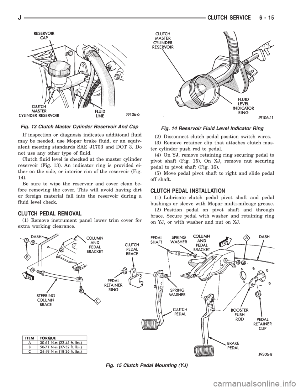
Clutch fluid level is checked at the master cylinder
reservoir (Fig. 13). An indicator ring is provided ei-
ther on the side, or interior rim of the reservoir (Fig.
14).
Be sure to wipe the reservoir and cover clean be-
fore removing the cover. This will avoid having dirt
or foreign material fall into the reservoir during a
fluid level check.
CLUTCH PEDAL REMOVAL
(1) Remove instrument panel lower trim cover for
extra working clearance.(2) Disconnect clutch pedal position switch wires.
(3) Remove retainer clip that attaches clutch mas-
ter cylinder push rod to pedal.
(4) On YJ, remove retaining ring securing pedal to
pivot shaft (Fig. 15). On XJ, remove nut securing
pedal to pivot shaft (Fig. 16).
(5) Move pedal pivot shaft to right and slide pedal
off shaft.
CLUTCH PEDAL INSTALLATION
(1) Lubricate clutch pedal pivot shaft and pedal
bushings or sleeve with Mopar multi-mileage grease.
(2) Position pedal on pivot shaft and through
brace. Secure pedal with washer and retaining ring
on YJ, or with washer and nut on XJ.
Fig. 13 Clutch Master Cylinder Reservoir And CapFig. 14 Reservoir Fluid Level Indicator Ring
Fig. 15 Clutch Pedal Mounting (YJ)
JCLUTCH SERVICE 6 - 15
Page 223 of 2198
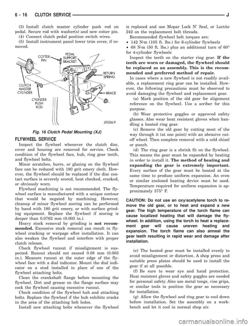
(3) Install clutch master cylinder push rod on
pedal. Secure rod with washer(s) and new cotter pin.
(4) Connect clutch pedal position switch wires.
(5) Install instrument panel lower trim cover, if re-
moved.
FLYWHEEL SERVICE
Inspect the flywheel whenever the clutch disc,
cover and housing are removed for service. Check
condition of the flywheel face, hub, ring gear teeth,
and flywheel bolts.
Minor scratches, burrs, or glazing on the flywheel
face can be reduced with 180 grit emery cloth. How-
ever, the flywheel should be replaced if the disc con-
tact surface is severely scored, heat checked, cracked,
or obviously worn.
Flywheel machining is not recommended. The fly-
wheel surface is manufactured with a unique contour
that would be negated by machining. However,
cleanup of minor flywheel scoring can be performed
by hand with 180 grit emery, or with surface grind-
ing equipment. Replace the flywheel if scoring is
deeper than 0.0762 mm (0.003 in.).
Heavy stock removal by grinding isnot recom-
mended.Excessive stock removal can result in fly-
wheel cracking or warpage after installation. It can
also weaken the flywheel and interfere with proper
clutch release.
Check flywheel runout if misalignment is sus-
pected. Runout should not exceed 0.08 mm (0.003
in.). Measure runout at the outer edge of the fly-
wheel face with a dial indicator. Mount the dial indi-
cator on a stud installed in place of one of the
flywheel attaching bolts.
Clean the crankshaft flange before mounting the
flywheel. Dirt and grease on the flange surface may
cock the flywheel causing excessive runout.
Check condition of the flywheel hub and attaching
bolts. Replace the flywheel if the hub exhibits cracks
in the area of the attaching bolt holes.
Install new attaching bolts whenever the flywheelis replaced and use Mopar Lock N' Seal, or Loctite
242 on the replacement bolt threads.
Recommended flywheel bolt torques are:
²142 Nzm (105 ft. lbs.) for 6-cylinder flywheels
²68 Nzm (50 ft. lbs.) plus an additional turn of 60É
for 4-cylinder flywheels
Inspect the teeth on the starter ring gear.If the
teeth are worn or damaged, the flywheel should
be replaced as an assembly. This is the recom-
mended and preferred method of repair.
In cases where a new flywheel is not readily avail-
able, a replacement ring gear can be installed. How-
ever, the following precautions must be observed to
avoid damaging the flywheel and replacement gear.
(a) Mark position of the old gear for alignment
reference on the flywheel. Use a scriber for this
purpose.
(b) Wear protective goggles or approved safety
glasses. Also wear heat resistent gloves when han-
dling a heated ring gear.
(c) Remove the old gear by cutting most of the
way through it (at one point) with an abrasive cut-
off wheel. Then complete removal with a cold chisel
or punch.
(d) The ring gear is a shrink fit on the flywheel.
This means the gear must be expanded by heating
in order to install it.The method of heating and
expanding the gear is extremely important.
Every surface of the gear must be heated at the
same time to produce uniform expansion. An oven
or similar enclosed heating device must be used.
Temperature required for uniform expansion is ap-
proximately 375É F.
CAUTION: Do not use an oxy/acetylene torch to re-
move the old gear, or to heat and expand a new
gear. The high temperature of the torch flame can
cause localized heating that will damage the fly-
wheel. In addition, using the torch to heat a replace-
ment gear will cause uneven heating and
expansion. The torch flame can also anneal the
gear teeth resulting in rapid wear and damage after
installation.
(e) The heated gear must be installed evenly to
avoid misalignment or distortion. A shop press and
suitable press plates should be used to install the
gear if at all possible.
(f) Be sure to wear eye and hand protection.
Heat resistent gloves and safety goggles are needed
for personal safety. Also use metal tongs, vise grips,
or similar tools to position the gear as necessary
for installation.
(g) Allow the flywheel and ring gear to cool down
before installation. Set the assembly on a work-
bench and let it cool in normal shop air.
Fig. 16 Clutch Pedal Mounting (XJ)
6 - 16 CLUTCH SERVICEJ
Page 229 of 2198
DIAGNOSIS
INDEX
page page
DRB Scan Tool............................ 5
On-Board Diagnostics (OBD).................. 4Preliminary Checks......................... 5
ON-BOARD DIAGNOSTICS (OBD)
FOR CERTAIN COOLING SYSTEM
COMPONENTS
The powertrain control module (PCM) has been
programmed to monitor the certain following cooling
system components:
²If the engine has remained cool for too long a pe-
riod, such as with a stuck open thermostat, a Diag-
nostic Trouble Code (DTC) number 17 can be
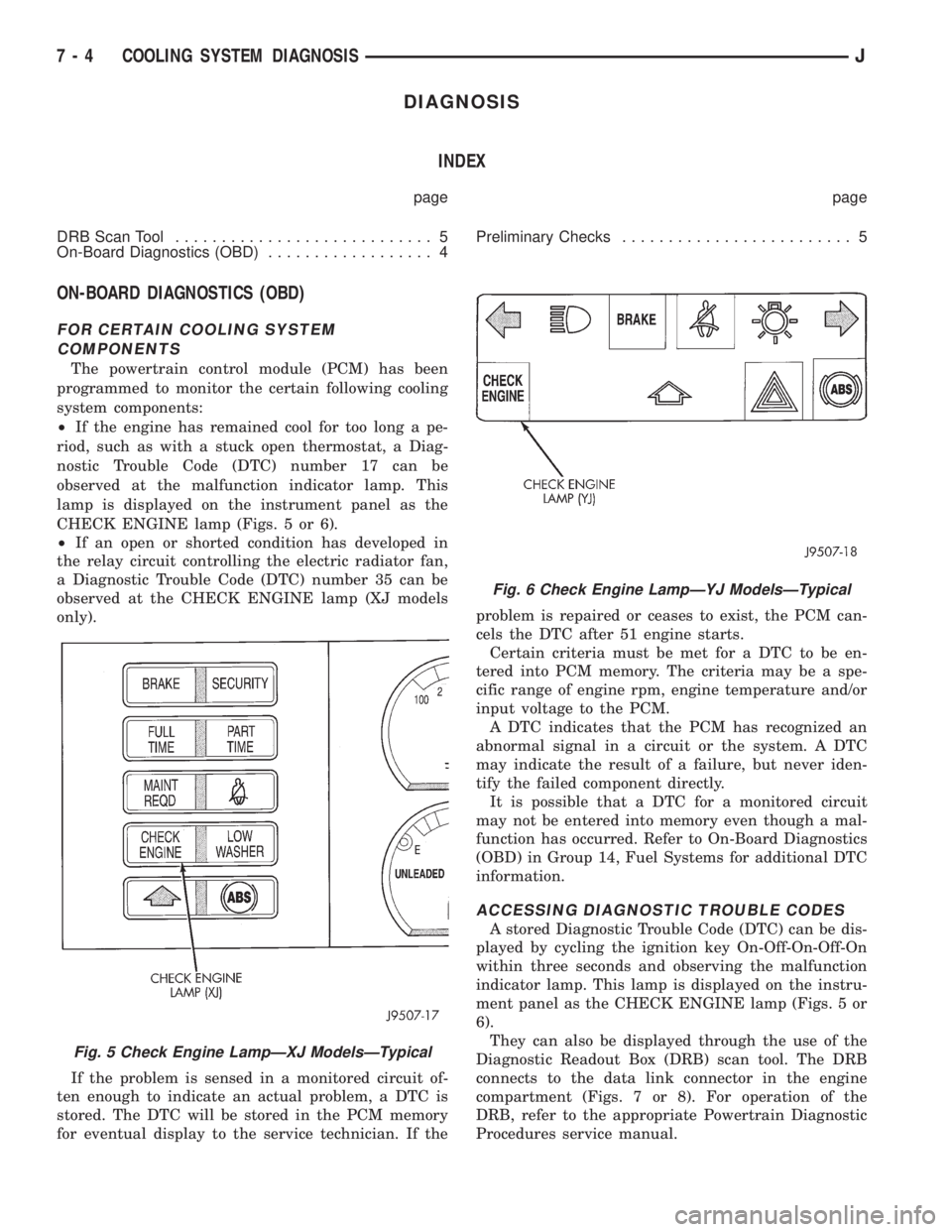
observed at the malfunction indicator lamp. This
lamp is displayed on the instrument panel as the
CHECK ENGINE lamp (Figs. 5 or 6).
²If an open or shorted condition has developed in
the relay circuit controlling the electric radiator fan,
a Diagnostic Trouble Code (DTC) number 35 can be
observed at the CHECK ENGINE lamp (XJ models
only).
If the problem is sensed in a monitored circuit of-
ten enough to indicate an actual problem, a DTC is
stored. The DTC will be stored in the PCM memory
for eventual display to the service technician. If theproblem is repaired or ceases to exist, the PCM can-
cels the DTC after 51 engine starts.
Certain criteria must be met for a DTC to be en-
tered into PCM memory. The criteria may be a spe-
cific range of engine rpm, engine temperature and/or
input voltage to the PCM.
A DTC indicates that the PCM has recognized an
abnormal signal in a circuit or the system. A DTC
may indicate the result of a failure, but never iden-
tify the failed component directly.
It is possible that a DTC for a monitored circuit
may not be entered into memory even though a mal-
function has occurred. Refer to On-Board Diagnostics
(OBD) in Group 14, Fuel Systems for additional DTC
information.
ACCESSING DIAGNOSTIC TROUBLE CODES
A stored Diagnostic Trouble Code (DTC) can be dis-
played by cycling the ignition key On-Off-On-Off-On
within three seconds and observing the malfunction
indicator lamp. This lamp is displayed on the instru-
ment panel as the CHECK ENGINE lamp (Figs. 5 or
6).
They can also be displayed through the use of the
Diagnostic Readout Box (DRB) scan tool. The DRB
connects to the data link connector in the engine
compartment (Figs. 7 or 8). For operation of the
DRB, refer to the appropriate Powertrain Diagnostic
Procedures service manual.
Fig. 5 Check Engine LampÐXJ ModelsÐTypical
Fig. 6 Check Engine LampÐYJ ModelsÐTypical
7 - 4 COOLING SYSTEM DIAGNOSISJ