1995 JEEP CHEROKEE service indicator
[x] Cancel search: service indicatorPage 274 of 2198
charged. However, even with these vents, hydrogen
gas can collect in or around the battery. If hydrogen
gas is exposed to flame or sparks, it can ignite.
If the electrolyte level is low, the battery could arc
internally and explode. If the battery is equipped
with removable cell caps, add distilled water when-
ever the electrolyte level is below the top of the
plates. If the battery cell caps cannot be removed, the
battery must be replaced when the electrolyte level is
low.
WARNING: DO NOT ATTEMPT TO ASSIST BOOST,
CHARGE, OR TEST BATTERY WHEN ELECTRO-
LYTE LEVEL IS BELOW THE TOP OF THE PLATES.
PERSONAL INJURY MAY OCCUR.
BATTERY RATINGS
Currently, there are 2 commonly accepted methods
for rating and comparing battery performance. These
ratings are called Cold Cranking Amperage (CCA),
and Reserve Capacity (RC). Be certain that a replace-
ment battery has CCA and RC ratings that equal or
exceed the original equipment specification for the
vehicle being serviced. See Battery Classifications
and Ratings charts in Specifications at the back of
this group.
COLD CRANKING AMPERAGE
The Cold Cranking Amperage (CCA) rating speci-
fies how much current (in amperes) the battery can
deliver for 30 seconds at -17.7ÉC (0ÉF). Terminal volt-
age must not fall below 7.2 volts during or after the
30 second discharge. The CCA required is generally
higher as engine displacement increases, depending
also upon the starter current draw requirements.
RESERVE CAPACITY
The Reserve Capacity (RC) rating specifies the
time (in minutes) it takes for battery terminal volt-
age to fall below 10.2 volts at a discharge rate of 25
amps. RC is determined with the battery fully-
charged at 26.7ÉC (80ÉF). This rating estimates how
long the battery might last after a charging system
failure, under minimum electrical load.
DIAGNOSIS
The battery must be completely charged and the
top, posts, and terminal clamps should be properly
cleaned before diagnostic procedures are performed.
Refer to Group 8B - Battery/Starter/Generator Ser-
vice for more information.
The condition of a battery is determined by two cri-
teria:
(1)State-Of-ChargeThis can be determined by
viewing the built-in test indicator, by checking spe-
cific gravity of the electrolyte (hydrometer test), or by
checking battery voltage (open circuit voltage test).(2)Cranking CapacityThis can be determined
by performing a battery load test, which measures
the ability of the battery to supply high-amperage
current.
If the battery has a built-in test indicator, use this
test first. If it has no test indicator, but has remov-
able cell caps, perform the hydrometer test first. If
cell caps are not removable, or a hydrometer is not
available, perform the open circuit voltage test first.
The battery must be charged before proceeding
with a load test if:
²the built-in test indicator has a black or dark color
visible
²the temperature corrected specific gravity is less
than 1.235
²the open circuit voltage is less than 12.4 volts.
A battery that will not accept a charge is faulty
and further testing is not required. A battery that is
fully-charged, but does not pass the load test is
faulty and must be replaced.
Completely discharged batteries may take
several hours to accept a charge. See Charging
Completely Discharged Battery.
A battery is fully-charged when:
²all cells are gassing freely during charging
²a green color is visible in the sight glass of the
built-in test indicator
²three corrected specific gravity tests, taken at
1-hour intervals, indicate no increase in specific grav-
ity
²open circuit voltage is 12.4 volts or greater.
ABNORMAL BATTERY DISCHARGING
Any of the following conditions can result in abnor-
mal battery discharging:
(1) Corroded battery posts and terminals.
(2) Loose or worn generator drive belt.
(3) Electrical loads that exceed the output of the
charging system, possibly due to equipment installed
after manufacture or repeated short trip use.
(4) Slow driving speeds (heavy traffic conditions) or
prolonged idling with high-amperage draw systems
in use.
(5) Faulty circuit or component causing excessive
ignition-off draw. See Ignition-Off Draw in this group
for diagnosis.
(6) Faulty charging system.
(7) Faulty or incorrect battery.
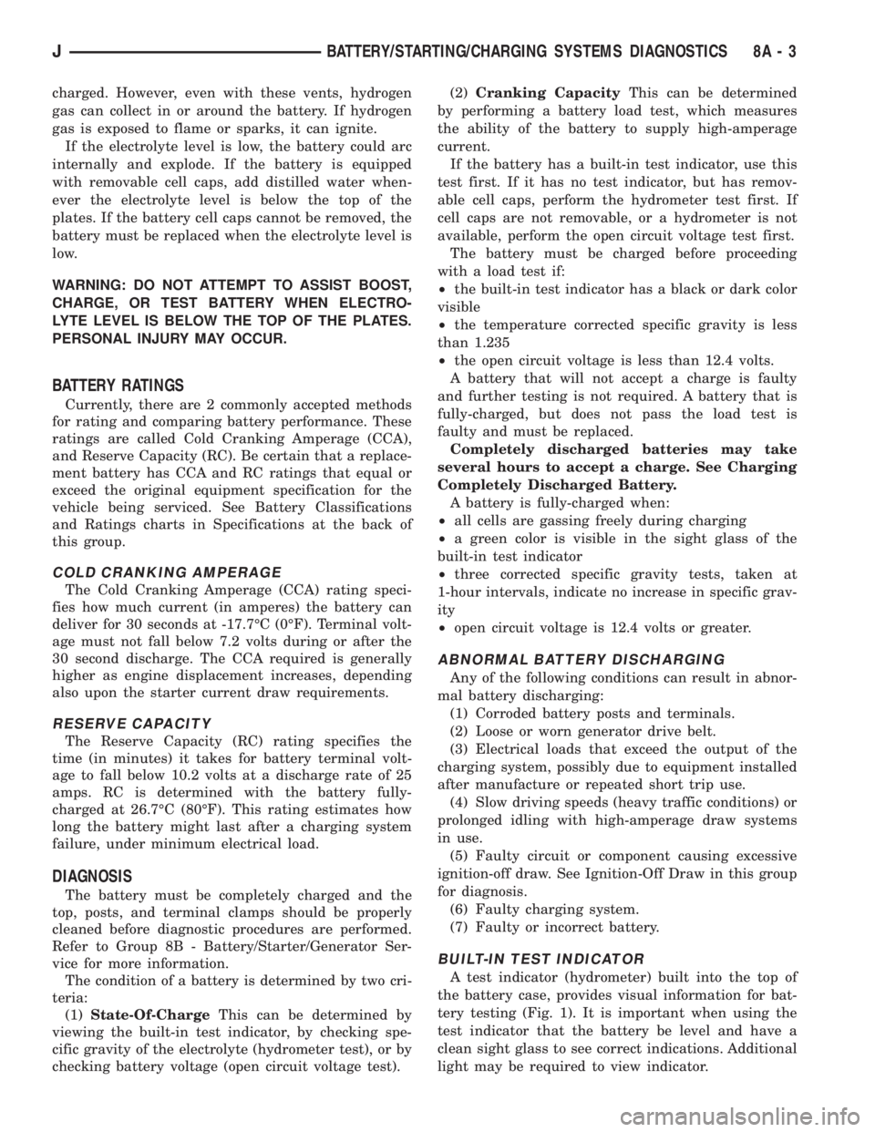
BUILT-IN TEST INDICATOR
A test indicator (hydrometer) built into the top of
the battery case, provides visual information for bat-
tery testing (Fig. 1). It is important when using the
test indicator that the battery be level and have a
clean sight glass to see correct indications. Additional
light may be required to view indicator.
JBATTERY/STARTING/CHARGING SYSTEMS DIAGNOSTICS 8A - 3
Page 276 of 2198
WARNING: DO NOT USE OPEN FLAME AS A
SOURCE OF ADDITIONAL LIGHT FOR VIEWING
TEST INDICATOR. EXPLOSIVE HYDROGEN GAS
MAY BE PRESENT IN THE AREA SURROUNDING
BATTERY.
Like a hydrometer, the built-in test indicator mea-
sures the specific gravity of the electrolyte. Specific
gravity will indicate battery state-of-charge. How-
ever, the test indicator will not indicate cranking ca-
pacity of the battery. See Load Test in this group for
more information.
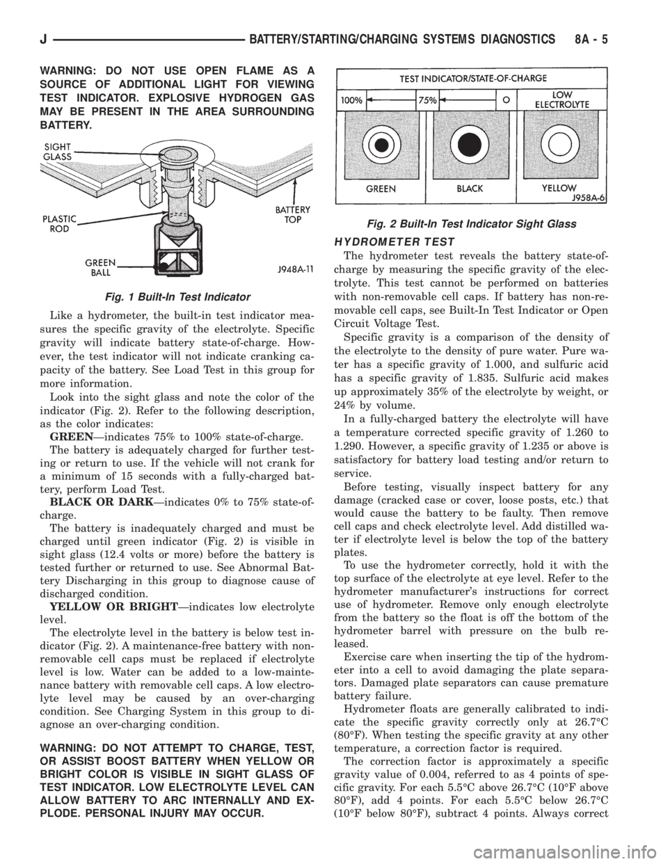
Look into the sight glass and note the color of the
indicator (Fig. 2). Refer to the following description,
as the color indicates:
GREENÐindicates 75% to 100% state-of-charge.
The battery is adequately charged for further test-
ing or return to use. If the vehicle will not crank for
a minimum of 15 seconds with a fully-charged bat-
tery, perform Load Test.
BLACK OR DARKÐindicates 0% to 75% state-of-
charge.
The battery is inadequately charged and must be
charged until green indicator (Fig. 2) is visible in
sight glass (12.4 volts or more) before the battery is
tested further or returned to use. See Abnormal Bat-
tery Discharging in this group to diagnose cause of
discharged condition.
YELLOW OR BRIGHTÐindicates low electrolyte
level.
The electrolyte level in the battery is below test in-
dicator (Fig. 2). A maintenance-free battery with non-
removable cell caps must be replaced if electrolyte
level is low. Water can be added to a low-mainte-
nance battery with removable cell caps. A low electro-
lyte level may be caused by an over-charging
condition. See Charging System in this group to di-
agnose an over-charging condition.
WARNING: DO NOT ATTEMPT TO CHARGE, TEST,
OR ASSIST BOOST BATTERY WHEN YELLOW OR
BRIGHT COLOR IS VISIBLE IN SIGHT GLASS OF
TEST INDICATOR. LOW ELECTROLYTE LEVEL CAN
ALLOW BATTERY TO ARC INTERNALLY AND EX-
PLODE. PERSONAL INJURY MAY OCCUR.
HYDROMETER TEST
The hydrometer test reveals the battery state-of-
charge by measuring the specific gravity of the elec-
trolyte. This test cannot be performed on batteries
with non-removable cell caps. If battery has non-re-
movable cell caps, see Built-In Test Indicator or Open
Circuit Voltage Test.
Specific gravity is a comparison of the density of
the electrolyte to the density of pure water. Pure wa-
ter has a specific gravity of 1.000, and sulfuric acid
has a specific gravity of 1.835. Sulfuric acid makes
up approximately 35% of the electrolyte by weight, or
24% by volume.
In a fully-charged battery the electrolyte will have
a temperature corrected specific gravity of 1.260 to
1.290. However, a specific gravity of 1.235 or above is
satisfactory for battery load testing and/or return to
service.
Before testing, visually inspect battery for any
damage (cracked case or cover, loose posts, etc.) that
would cause the battery to be faulty. Then remove
cell caps and check electrolyte level. Add distilled wa-
ter if electrolyte level is below the top of the battery
plates.
To use the hydrometer correctly, hold it with the
top surface of the electrolyte at eye level. Refer to the
hydrometer manufacturer's instructions for correct
use of hydrometer. Remove only enough electrolyte
from the battery so the float is off the bottom of the
hydrometer barrel with pressure on the bulb re-
leased.
Exercise care when inserting the tip of the hydrom-
eter into a cell to avoid damaging the plate separa-
tors. Damaged plate separators can cause premature
battery failure.
Hydrometer floats are generally calibrated to indi-
cate the specific gravity correctly only at 26.7ÉC
(80ÉF). When testing the specific gravity at any other
temperature, a correction factor is required.
The correction factor is approximately a specific
gravity value of 0.004, referred to as 4 points of spe-
cific gravity. For each 5.5ÉC above 26.7ÉC (10ÉF above
80ÉF), add 4 points. For each 5.5ÉC below 26.7ÉC
(10ÉF below 80ÉF), subtract 4 points. Always correct
Fig. 1 Built-In Test Indicator
Fig. 2 Built-In Test Indicator Sight Glass
JBATTERY/STARTING/CHARGING SYSTEMS DIAGNOSTICS 8A - 5
Page 288 of 2198
CHARGING SYSTEM
GENERAL INFORMATION
The charging system consists of:
²generator
²voltage regulator circuitry (within PCM)
²ignition switch
²battery
²generator warning lamp or voltmeter (depending
on vehicle equipment)
²wiring harness and connections.
Following is a general description of the major
charging system components. Refer to Group 8W -
Wiring Diagrams for complete circuit descriptions
and diagrams.
The charging system is turned on and off with the
ignition switch. When the ignition switch is turned to
the ON position, battery voltage is applied to the
generator rotor through one of the two field termi-
nals to produce a magnetic field. The generator is
driven by the engine through a serpentine belt and
pulley arrangement.
As the energized rotor begins to rotate within the
generator, the spinning magnetic field induces a cur-
rent into the windings of the stator coil. Once the
generator begins producing sufficient current, it also
provides the current needed to energize the rotor.
The wye (Y) type stator winding connections de-
liver the induced AC current to 3 positive and 3 neg-
ative diodes for rectification. From the diodes,
rectified DC current is delivered to the vehicle elec-
trical system through the generator battery and
ground terminals.
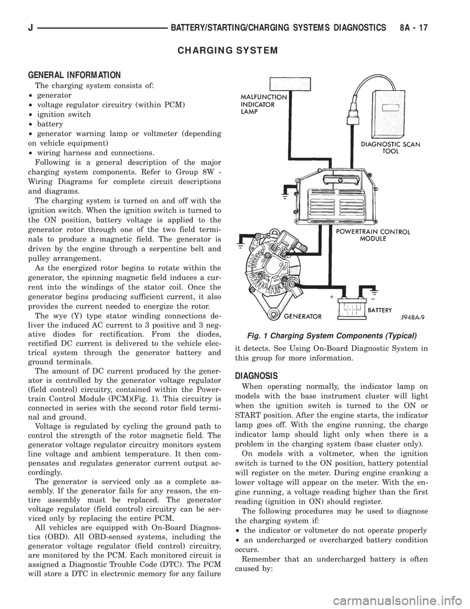
The amount of DC current produced by the gener-
ator is controlled by the generator voltage regulator
(field control) circuitry, contained within the Power-
train Control Module (PCM)(Fig. 1). This circuitry is
connected in series with the second rotor field termi-
nal and ground.
Voltage is regulated by cycling the ground path to
control the strength of the rotor magnetic field. The
generator voltage regulator circuitry monitors system
line voltage and ambient temperature. It then com-
pensates and regulates generator current output ac-
cordingly.
The generator is serviced only as a complete as-
sembly. If the generator fails for any reason, the en-
tire assembly must be replaced. The generator
voltage regulator (field control) circuitry can be ser-
viced only by replacing the entire PCM.
All vehicles are equipped with On-Board Diagnos-
tics (OBD). All OBD-sensed systems, including the
generator voltage regulator (field control) circuitry,
are monitored by the PCM. Each monitored circuit is
assigned a Diagnostic Trouble Code (DTC). The PCM
will store a DTC in electronic memory for any failureit detects. See Using On-Board Diagnostic System in
this group for more information.
DIAGNOSIS
When operating normally, the indicator lamp on
models with the base instrument cluster will light
when the ignition switch is turned to the ON or
START position. After the engine starts, the indicator
lamp goes off. With the engine running, the charge
indicator lamp should light only when there is a
problem in the charging system (base cluster only).
On models with a voltmeter, when the ignition
switch is turned to the ON position, battery potential
will register on the meter. During engine cranking a
lower voltage will appear on the meter. With the en-
gine running, a voltage reading higher than the first
reading (ignition in ON) should register.
The following procedures may be used to diagnose
the charging system if:
²the indicator or voltmeter do not operate properly
²an undercharged or overcharged battery condition
occurs.
Remember that an undercharged battery is often
caused by:
Fig. 1 Charging System Components (Typical)
JBATTERY/STARTING/CHARGING SYSTEMS DIAGNOSTICS 8A - 17
Page 326 of 2198
To test ignition coil-to-distributor cap cable, do not
remove the cable from the cap. Connect ohmmeter to
rotor button (center contact) of distributor cap and
terminal at ignition coil end of cable. If resistance is
not within specifications as found in the Spark Plug
Cable Resistance chart, remove the cable from the
distributor cap. Connect the ohmmeter to the termi-
nal ends of the cable. If resistance is not within spec-
ifications as found in the Spark Plug Cable
Resistance chart, replace the cable. Inspect the igni-
tion coil tower for cracks, burns or corrosion.
For removal and installation of spark plug cables,
refer to Spark Plug Secondary Cables in the Compo-
nent Removal/Installation section.
THROTTLE POSITION SENSOR TEST
For an operational description, diagnosis and re-
moval/installation procedures, refer to Group 14,
Fuel System.
OXYGEN (O2S) SENSOR TESTS
For an operational description, diagnosis or remov-
al/ installation procedures, refer to Group 14, Fuel
Systems.
ON-BOARD DIAGNOSTICS
FOR CERTAIN IGNITION SYSTEM
COMPONENTS
The powertrain control module (PCM) performs an
On-Board Diagnostic (OBD) check for certain ignition
system components on all vehicles. This is done by
setting a diagnostic trouble code (DTC).
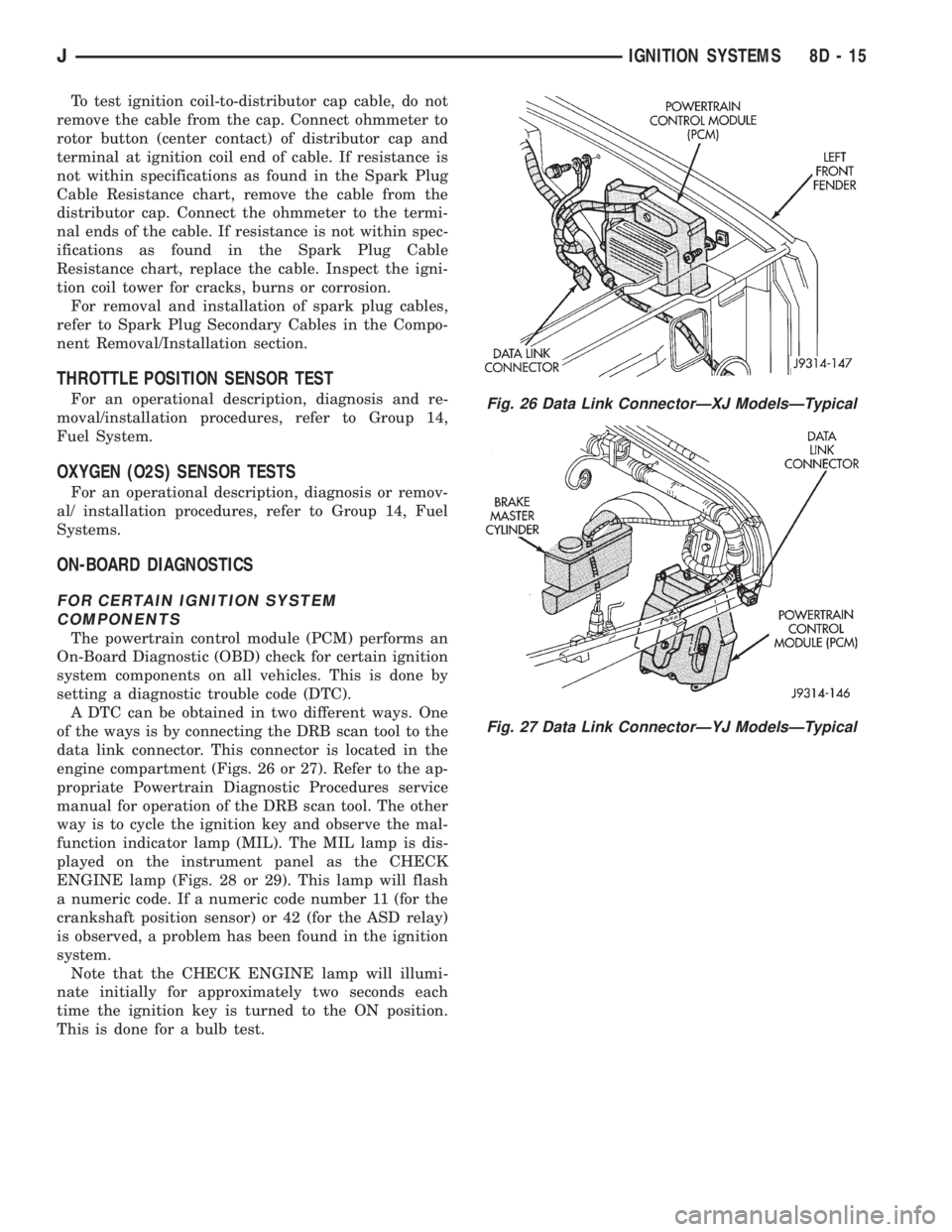
A DTC can be obtained in two different ways. One
of the ways is by connecting the DRB scan tool to the
data link connector. This connector is located in the
engine compartment (Figs. 26 or 27). Refer to the ap-
propriate Powertrain Diagnostic Procedures service
manual for operation of the DRB scan tool. The other
way is to cycle the ignition key and observe the mal-
function indicator lamp (MIL). The MIL lamp is dis-
played on the instrument panel as the CHECK
ENGINE lamp (Figs. 28 or 29). This lamp will flash
a numeric code. If a numeric code number 11 (for the
crankshaft position sensor) or 42 (for the ASD relay)
is observed, a problem has been found in the ignition
system.
Note that the CHECK ENGINE lamp will illumi-
nate initially for approximately two seconds each
time the ignition key is turned to the ON position.
This is done for a bulb test.
Fig. 26 Data Link ConnectorÐXJ ModelsÐTypical
Fig. 27 Data Link ConnectorÐYJ ModelsÐTypical
JIGNITION SYSTEMS 8D - 15
Page 344 of 2198

INSTRUMENT PANEL AND GAUGES
GROUP INDEX
INSTRUMENT PANEL AND GAUGESÐXJ...... 1INSTRUMENT PANEL AND GAUGESÐYJ..... 24
INSTRUMENT PANEL AND GAUGESÐXJ
CONTENTS
page page
DIAGNOSIS............................. 5
GENERAL INFORMATION.................. 1SERVICE PROCEDURES.................. 17
SPECIFICATIONS........................ 23
GENERAL INFORMATION
Following are general descriptions of major instru-
ment panel components. Refer to Group 8W - Wiring
Diagrams for complete circuit descriptions and dia-
grams.
INSTRUMENT PANEL
Modular instrument panel construction allows all
gauges and controls to be serviced from the front of
the panel. In addition, most instrument panel wiring
or heater and air conditioning components can be ac-
cessed without complete instrument panel removal. If
necessary, the instrument panel can be rolled-down
and removed from the vehicle as an assembly.
Removal of the instrument cluster bezel allows ac-
cess to the cluster assembly, most switches, the cli-
mate controls, and the radio. Removal of the cluster
assembly allows access to the individual gauges, illu-
mination and indicator lamp bulbs, printed circuits,
and most wiring.
Removal of the lower instrument panel allows ac-
cess to heater and air conditioning components, the
fuseblock module, the relay center, and other wiring
and electrical components. Those models equipped
with a driver's-side airbag restraint have a knee
blocker and reinforcement behind the driver's-side
lower instrument panel.
The instrument panel layout is mirror image for
left-hand and right-hand drive vehicles. In most
cases, the diagnosis and service procedures found in
this group are applicable to either vehicle. Although,most illustrations represent only the typical left-hand
drive version. Exceptions are clearly identified as
Right-Hand Drive (RHD).
INSTRUMENT CLUSTERS
Two basic instrument cluster options are offered on
XJ (Cherokee) models. One is referred to as a low-
line cluster, and the other is referred to as a high-
line cluster. Each cluster is divided into two areas:
the gauge area, and the tell-tale area. Each area is
served by a separate printed circuit and wiring con-
nector. Some variations of each cluster exist due to
optional equipment and regulatory requirements.
The low-line cluster includes the following gauges:
²fuel gauge
²speedometer/odometer.
The low-line cluster includes provisions for the fol-
lowing indicator lamps:
²anti-lock brake system lamp
²brake warning lamp
²coolant temperature warning lamp
²four-wheel drive indicator lamps
²generator warning lamp
²headlamp high beam indicator lamp
²low oil pressure warning lamp
²low washer fluid warning lamp
²malfunction indicator (Check Engine) lamp
²seat belt reminder lamp
²turn signal indicator lamps
²upshift indicator lamp.
JINSTRUMENT PANEL AND GAUGES 8E - 1
Page 346 of 2198
TACHOMETER
The tachometer gives an indication of engine speed
in Revolutions-Per-Minute (RPM). With the engine
running, the tachometer receives an engine speed
pulse signal from the Powertrain Control Module
(PCM). An electronic integrated circuit contained
within the tachometer reads and analyzes the pulse
signal. It then adjusts the ground path resistance of
one electromagnet in the gauge to control needle
movement. Frequency values for the pulse signal are
shown in a chart in Specifications.
TRIP ODOMETER
The trip odometer is driven by the same electronic
integrated circuit as the speedometer/odometer. How-
ever, by depressing the trip odometer reset knob on
the face of the speedometer, the trip odometer can be
reset to zero. The trip odometer is serviced only as a
part of the speedometer/odometer gauge assembly.
VOLTMETER
The voltmeter is connected in parallel with the bat-
tery. With the ignition switch ON, the voltmeter in-
dicates battery or generator output voltage,
whichever is greater.
INDICATOR LAMPS
Indicator lamps are located in two areas within the
cluster. Each of these areas is served by a separate
printed circuit and cluster connector. Those lamps in
the gauge area of the cluster share the gauge area
printed circuit and cluster connector A. Those lamps
in the tell-tale area of the cluster use the tell-tale
printed circuit and cluster (tell-tale) connector B.
Up to ten indicator lamps can be found in the tell-
tale area of the cluster. These lamps are arranged in
five stacked rows with two lamps in each row, located
to the driver's side of the main cluster.
ANTI-LOCK BRAKE SYSTEM LAMP
The Anti-Lock Brake System (ABS) lamp is
switched to ground by the ABS module. The module
lights the lamp when the ignition switch is turned to
the START position as a bulb test. The lamp will
stay on for 3 to 5 seconds after vehicle start-up to in-
dicate a system self-test is in process. If the lamp re-
mains on after start-up, or comes on and stays on
while driving, it may indicate that the ABS module
has detected a system malfunction or that the system
has become inoperative. Refer to Group 5 - Brakes
for more information.
BRAKE WARNING LAMP
The brake warning lamp warns the driver that the
parking brake is applied or that the pressures in the
two halves of the split brake hydraulic system are
unequal. With the ignition switch turned ON, batteryvoltage is supplied to one side of the indicator bulb. A
ground path for the bulb is provided by 3 switches.
The bulb will light when:
²the brake warning switch is closed (indicating un-
equal brake system hydraulic pressures possibly due
to brake fluid leakage)
²the ignition switch is in the START position (bulb
test)
²the parking brake switch is closed (parking brake
is applied).
Refer to Group 5 - Brakes for more information.
COOLANT TEMPERATURE WARNING LAMP
The coolant temperature warning lamp lights
whenever engine coolant temperature is too high.
Battery voltage is supplied to one side of the indica-
tor bulb when the ignition switch is turned ON. The
normally open coolant temperature switch is con-
nected to the other side of the bulb. When coolant
temperature is too high, the switch closes. This pro-
vides a ground path for the indicator bulb, which
causes it to light. The lamp is also grounded and
should light with the ignition switch in the START
position as a bulb test.
FOUR-WHEEL DRIVE INDICATOR LAMPS
PART TIME
On vehicles with Command-Trac 4WD, the Part
Time lamp lights when the transfer case is engaged
in the 4H or 4L position. On vehicles with Selec-Trac
4WD, the Part Time lamp lights when the transfer
case is engaged in the4X4PARTTIME or 4 LO po-
sition. Voltage is supplied to one side of the indicator
bulb. A switch in the transfer case is connected to the
other side of the indicator bulb. When the switch is
closed, a path to ground is provided and the indicator
bulb lights.
FULL TIME
The Full Time lamp is only operational on vehicles
equipped with Selec-Trac 4WD. The Full Time lamp
lights when the transfer case is engaged in the4X4
Full Time position. Voltage is supplied to one side of
the indicator bulb. A switch in the transfer case is
connected to the other side of the indicator bulb.
When the switch is closed, a path to ground is pro-
vided and the indicator bulb lights.
GENERATOR WARNING LAMP
The generator warning lamp lights with the igni-
tion switch turned to ON, but should go out when-
ever the engine is running. If the lamp comes on and
stays on while the engine is running, it indicates
that a charging system malfunction exists. One side
of the bulb is connected to ignition-switched battery
feed. The other side of the bulb is switched to ground
by the Powertrain Control Module (PCM).
JINSTRUMENT PANEL AND GAUGESÐXJ 8E - 3
Page 355 of 2198
INDICATOR LAMPS
If an individual indicator lamp is inoperative, see
the diagnostic procedure under the heading for that
lamp. If more than one indicator lamp or a combina-
tion of lamps and gauges in the gauge area of the in-
strument cluster is inoperative, see Gauges in this
section for diagnosis.
If more than one indicator lamp in the tell-tale
area of the cluster is inoperative, perform the follow-
ing:
(1) Check fuse 17 (fuse 26 - RHD) in the fuseblock
module. If OK, go to next step. If not OK, replace
fuse.
(2) Check for battery voltage at fuse 17 (fuse 26 -
RHD) with ignition switch in ON position. If OK, go
to next step. If not OK, repair circuit to ignition
switch and/or refer to Group 8D - Ignition Systems
for testing of ignition switch.
(3) Turn ignition switch to OFF. Disconnect battery
negative cable. Remove instrument cluster bezel and
cluster assembly. Unplug cluster (tell-tale) connector
B.
(4) Connect battery negative cable. Turn ignition
switch to ON. Check for battery voltage at cavities 3,
4, and 14 (cavities 3 and 14 - RHD) of cluster connec-
tor B. If OK, go to next step. If not OK, repair open
circuit to fuse 17 (fuse 26 - RHD) as required.
(5) Turn ignition switch to OFF. Disconnect battery
negative cable. Probe cavity 16 (cavity 1 - RHD) of
cluster connector B. Check for continuity to a good
ground. There should be continuity. If OK, replace
cluster tell-tale printed circuit. If not OK, repair open
circuit to ground as required.
ANTI-LOCK BRAKE SYSTEM LAMP
The diagnosis found here addresses an inoperative
lamp condition. If the ABS lamp stays on with the ig-
nition switch in the ON position, or comes on and
stays on while driving, refer to Group 5 - Brakes for
diagnosis. If no ABS problem is found, the following
procedure will help locate a short or open in the ABS
lamp circuit.
(1) Disconnect battery negative cable. Remove in-
strument cluster bezel and cluster assembly. Discon-
nect ABS control module connector.
(2) Install a jumper wire between cavity 6 of clus-
ter (tell-tale) connector B and a good ground. Connect
battery negative cable and turn ignition switch to
ON. Lamp should light. If OK, remove jumper wire
and go to next step. If not OK, replace bulb.
(3) Turn ignition switch to OFF. Disconnect battery
negative cable and unplug cluster connector B. Check
for continuity between cavity 6 of cluster connector B
and a good ground. There should be no continuity. If
OK, go to next step. If not OK, repair short circuit as
required.(4) Check continuity between cavity 6 of cluster
connector B and cavity 52 of ABS control module con-
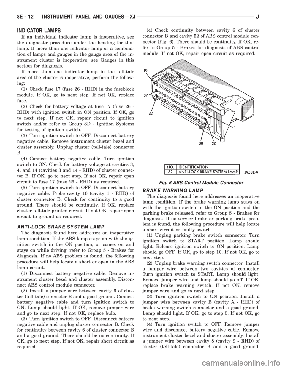
nector (Fig. 6). There should be continuity. If OK, re-
fer to Group 5 - Brakes for diagnosis of ABS control
module. If not OK, repair open circuit as required.
BRAKE WARNING LAMP
The diagnosis found here addresses an inoperative
lamp condition. If the brake warning lamp stays on
with the ignition switch in the ON position and the
parking brake released, refer to Group 5 - Brakes for
diagnosis. If no service brake or parking brake prob-
lem is found, the following procedure will help locate
a short circuit or faulty switch.
(1) Unplug parking brake switch connector. Turn
ignition switch to START position. Lamp should
light. Release ignition switch to ON position. Lamp
should go OFF. If OK, go to step 10. If not OK, go to
next step.
(2) Unplug brake warning switch connector. Install
a jumper wire between two cavities of connector.
Turn ignition switch to START. Lamp should light.
Remove jumper wire and lamp should go off. If OK,
replace brake warning switch. If not OK, remove
jumper wire and go to next step.
(3) Turn ignition switch to ON position. Install a
jumper wire between cavity B (cavity A - RHD) of
brake warning switch connector and a good ground.
Lamp should light. If OK, go to step 5. If not OK, go
to next step.
(4) Turn ignition switch to OFF. Remove jumper
wire and disconnect battery negative cable. Remove
instrument cluster bezel and cluster assembly. Install
a jumper wire between cavity 8 (cavity 9 - RHD) of
cluster (tell-tale) connector B and a good ground.
Fig. 6 ABS Control Module Connector
8E - 12 INSTRUMENT PANEL AND GAUGESÐXJJ
Page 367 of 2198
INSTRUMENT PANEL AND GAUGESÐYJ
CONTENTS
page page
INSTRUMENT PANEL AND GAUGESÐYJ..... 22
DIAGNOSIS............................ 23
GENERAL INFORMATION................. 20SERVICE PROCEDURES.................. 31
SPECIFICATIONS........................ 39
GENERAL INFORMATION
Following are general descriptions of major instru-
ment panel components. Refer to Group 8W - Wiring
Diagrams for complete circuit descriptions and dia-
grams.
INSTRUMENT PANEL
Modular instrument panel construction allows all
gauges and controls to be serviced from the front of
the panel. In addition, most instrument panel wiring
and heater components can be accessed without com-
plete instrument panel removal.
Removal of the left instrument cluster bezel allows
access to the main cluster assembly and most
switches. Removal of the center cluster bezel allows
access to the gauge package cluster assembly, the
heater controls, and the radio. Removal of the cluster
assemblies allows access to the individual gauges, il-
lumination and indicator lamp bulbs, printed cir-
cuits, and most wiring.
INSTRUMENT CLUSTERS
The instrument cluster used on YJ (Wrangler) mod-
els consists of two separate assemblies. The main
cluster assembly is located on the left side of the in-
strument panel, centered over the steering column
opening. The gauge package cluster assembly is lo-
cated near the center of the instrument panel. Each
cluster assembly is served by a separate printed cir-
cuit and wiring connector. Some variations of each
cluster exist due to optional equipment and regula-
tory requirements.
The main cluster assembly includes a speedometer/
odometer/trip odometer and a tachometer. It also in-
cludes provisions for the following indicator lamps:
²anti-lock brake system lamp
²brake warning lamp
²headlamp high beam indicator lamp
²malfunction indicator (Check Engine) lamp
²seat belt reminder lamp²turn signal indicator lamps
²upshift indicator lamp.
The gauge package cluster assembly includes a
four-wheel drive indicator lamp and the following
gauges:
²coolant temperature gauge
²fuel gauge
²oil pressure gauge
²voltmeter.
GAUGES
With the ignition switch in the ON or START posi-
tion, voltage is supplied to all gauges through the
two cluster printed circuits. With the ignition switch
in the OFF position, voltage is not supplied to the
gauges. A gauge pointer may remain within the
gauge scale after the ignition switch is OFF. How-
ever, the gauges do not accurately indicate any vehi-
cle condition unless the ignition switch is ON.
All gauges except the odometer are air core mag-
netic units. Two fixed electromagnetic coils are lo-
cated within the gauge. These coils are wrapped at
right angles to each other around a movable perma-
nent magnet. The movable magnet is suspended
within the coils on one end of a shaft. The gauge nee-
dle is attached to the other end of the shaft.
One of the coils has a fixed current flowing through
it to maintain a constant magnetic field strength.
Current flow through the second coil changes, which
causes changes in its magnetic field strength. The
current flowing through the second coil can be
changed by:
²a variable resistor-type sending unit (fuel level,
coolant temperature, or oil pressure)
²changes in electrical system voltage (voltmeter)
²electronic control circuitry (speedometer/odometer,
tachometer).
8E - 24 INSTRUMENT PANEL AND GAUGESÐYJJ