1995 JEEP CHEROKEE open gas tank
[x] Cancel search: open gas tankPage 248 of 2198
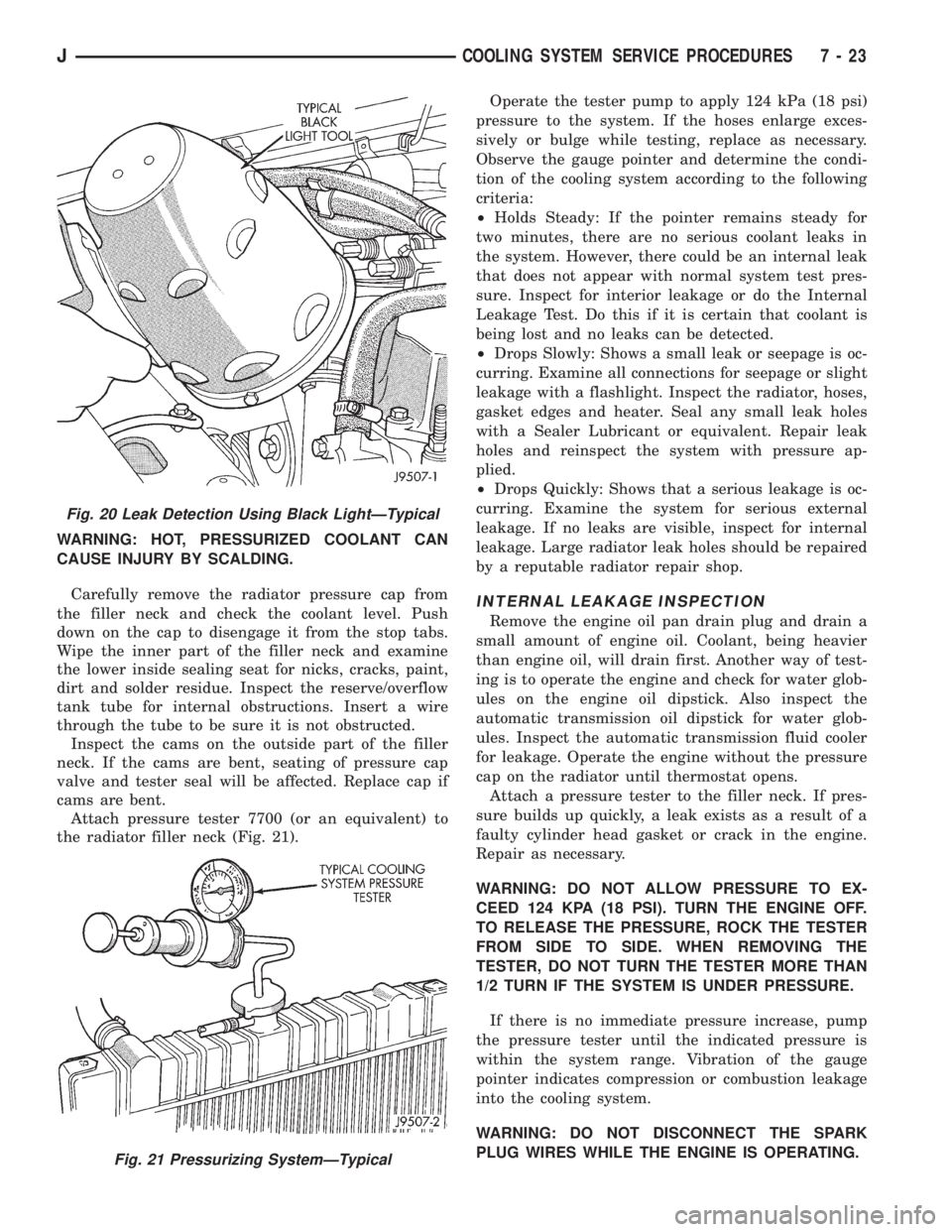
WARNING: HOT, PRESSURIZED COOLANT CAN
CAUSE INJURY BY SCALDING.
Carefully remove the radiator pressure cap from
the filler neck and check the coolant level. Push
down on the cap to disengage it from the stop tabs.
Wipe the inner part of the filler neck and examine
the lower inside sealing seat for nicks, cracks, paint,
dirt and solder residue. Inspect the reserve/overflow
tank tube for internal obstructions. Insert a wire
through the tube to be sure it is not obstructed.
Inspect the cams on the outside part of the filler
neck. If the cams are bent, seating of pressure cap
valve and tester seal will be affected. Replace cap if
cams are bent.
Attach pressure tester 7700 (or an equivalent) to
the radiator filler neck (Fig. 21).Operate the tester pump to apply 124 kPa (18 psi)
pressure to the system. If the hoses enlarge exces-
sively or bulge while testing, replace as necessary.
Observe the gauge pointer and determine the condi-
tion of the cooling system according to the following
criteria:
²Holds Steady: If the pointer remains steady for
two minutes, there are no serious coolant leaks in
the system. However, there could be an internal leak
that does not appear with normal system test pres-
sure. Inspect for interior leakage or do the Internal
Leakage Test. Do this if it is certain that coolant is
being lost and no leaks can be detected.
²Drops Slowly: Shows a small leak or seepage is oc-
curring. Examine all connections for seepage or slight
leakage with a flashlight. Inspect the radiator, hoses,
gasket edges and heater. Seal any small leak holes
with a Sealer Lubricant or equivalent. Repair leak
holes and reinspect the system with pressure ap-
plied.
²Drops Quickly: Shows that a serious leakage is oc-
curring. Examine the system for serious external
leakage. If no leaks are visible, inspect for internal
leakage. Large radiator leak holes should be repaired
by a reputable radiator repair shop.
INTERNAL LEAKAGE INSPECTION
Remove the engine oil pan drain plug and drain a
small amount of engine oil. Coolant, being heavier
than engine oil, will drain first. Another way of test-
ing is to operate the engine and check for water glob-
ules on the engine oil dipstick. Also inspect the
automatic transmission oil dipstick for water glob-
ules. Inspect the automatic transmission fluid cooler
for leakage. Operate the engine without the pressure
cap on the radiator until thermostat opens.
Attach a pressure tester to the filler neck. If pres-
sure builds up quickly, a leak exists as a result of a
faulty cylinder head gasket or crack in the engine.
Repair as necessary.
WARNING: DO NOT ALLOW PRESSURE TO EX-
CEED 124 KPA (18 PSI). TURN THE ENGINE OFF.
TO RELEASE THE PRESSURE, ROCK THE TESTER
FROM SIDE TO SIDE. WHEN REMOVING THE
TESTER, DO NOT TURN THE TESTER MORE THAN
1/2 TURN IF THE SYSTEM IS UNDER PRESSURE.
If there is no immediate pressure increase, pump
the pressure tester until the indicated pressure is
within the system range. Vibration of the gauge
pointer indicates compression or combustion leakage
into the cooling system.
WARNING: DO NOT DISCONNECT THE SPARK
PLUG WIRES WHILE THE ENGINE IS OPERATING.
Fig. 20 Leak Detection Using Black LightÐTypical
Fig. 21 Pressurizing SystemÐTypical
JCOOLING SYSTEM SERVICE PROCEDURES 7 - 23
Page 249 of 2198

CAUTION: Do not operate the engine with a spark
plug shorted for more than a minute. The catalytic
converter may be damaged.
Isolate the compression leak by shorting each
spark plug to the cylinder block. The gauge pointer
should stop or decrease vibration when spark plug
for leaking cylinder is shorted. This happens because
of the absence of combustion pressure.
COMBUSTION LEAKAGE TEST (WITHOUT
PRESSURE TESTER)
DO NOT WASTE reusable coolant. If the solution
is clean, drain the coolant into a clean container for
reuse.
WARNING: DO NOT REMOVE THE CYLINDER
BLOCK DRAIN PLUGS OR LOOSEN THE RADIATOR
DRAINCOCK WITH THE SYSTEM HOT AND UNDER
PRESSURE. SERIOUS BURNS FROM COOLANT
CAN OCCUR.
Drain sufficient coolant to allow for thermostat re-
moval. Refer to Thermostat Replacement. Disconnect
the water pump drive belt.
Disconnect the upper radiator hose from the ther-
mostat housing. Remove the housing and thermostat.
Install the thermostat housing.
Add coolant to the radiator to bring the level to
within 6.3 mm (1/4 in) of the top of the thermostat
housing.
CAUTION: Avoid overheating. Do not operate the
engine for an excessive period of time. Open the
draincock immediately after the test to eliminate
boil over of coolant.
Start the engine and accelerate rapidly three times
(to approximately 3000 rpm) while observing the
coolant. If internal engine combustion gases are leak-
ing into the cooling system, bubbles will appear in
the coolant. If bubbles do not appear, there is no in-
ternal combustion gas leakage.
COOLANT RESERVE/OVERFLOW SYSTEM
The system works along with the radiator pressure
cap. This is done by using thermal expansion and
contraction of the coolant to keep the coolant free of
trapped air. It provides:
²A volume for coolant expansion and contraction.
²A convenient and safe method for checking/adjust-
ing coolant level at atmospheric pressure. This is
done without removing the radiator pressure cap.
²Some reserve coolant to the radiator to cover mi-
nor leaks and evaporation or boiling losses.
As the engine cools, a vacuum is formed in the
cooling system of both the radiator and engine. Cool-ant will then be drawn from the coolant tank and re-
turned to a proper level in the radiator.
The coolant reserve/overflow system consists of a
radiator mounted pressurized cap, a plastic reserve/
overflow tank (Figs. 22, 23 or 24), a tube (hose) con-
necting the radiator and tank, and an overflow tube
on the side of the tank.
Fig. 22 Reserve/Overflow TankÐYJ Models
Fig. 23 Reserve/Overflow TankÐXJ ModelsÐExcept
Right Hand Drive
7 - 24 COOLING SYSTEM SERVICE PROCEDURESJ
Page 250 of 2198
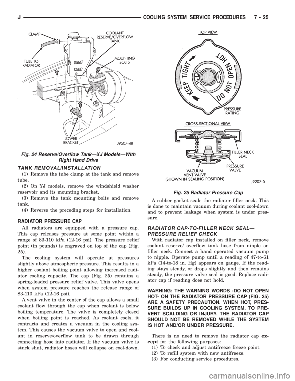
TANK REMOVAL/INSTALLATION
(1) Remove the tube clamp at the tank and remove
tube.
(2) On YJ models, remove the windshield washer
reservoir and its mounting bracket.
(3) Remove the tank mounting bolts and remove
tank.
(4) Reverse the preceding steps for installation.
RADIATOR PRESSURE CAP
All radiators are equipped with a pressure cap.
This cap releases pressure at some point within a
range of 83-110 kPa (12-16 psi). The pressure relief
point (in pounds) is engraved on top of the cap (Fig.
25).
The cooling system will operate at pressures
slightly above atmospheric pressure. This results in a
higher coolant boiling point allowing increased radi-
ator cooling capacity. The cap (Fig. 25) contains a
spring-loaded pressure relief valve. This valve opens
when system pressure reaches the release range of
83-110 kPa (12-16 psi).
A vent valve in the center of the cap allows a small
coolant flow through the cap when coolant is below
boiling temperature. The valve is completely closed
when boiling point is reached. As coolant cools, it
contracts and creates a vacuum in the cooling sys-
tem. This causes the vacuum valve to open and cool-
ant in reserve/overflow tank to be drawn through
connecting hose into radiator. If the vacuum valve is
stuck shut, radiator hoses will collapse on cool-down.A rubber gasket seals the radiator filler neck. This
is done to maintain vacuum during coolant cool-down
and to prevent leakage when system is under pres-
sure.RADIATOR CAP-TO-FILLER NECK SEALÐ
PRESSURE RELIEF CHECK
With radiator cap installed on filler neck, remove
coolant reserve/ overflow tank hose from nipple on
filler neck. Connect a hand operated vacuum pump
to nipple. Operate pump until a reading of 47-to-61
kPa (14-to-18 in. Hg) appears on gauge. If the read-
ing stays steady, or drops slightly and then remains
steady, the pressure valve seal is good. Replace radi-
ator cap if reading does not hold.
WARNING: THE WARNING WORDS -DO NOT OPEN
HOT- ON THE RADIATOR PRESSURE CAP (FIG. 25)
ARE A SAFETY PRECAUTION. WHEN HOT, PRES-
SURE BUILDS UP IN COOLING SYSTEM. TO PRE-
VENT SCALDING OR INJURY, THE RADIATOR CAP
SHOULD NOT BE REMOVED WHILE THE SYSTEM
IS HOT AND/OR UNDER PRESSURE.
There is no need to remove the radiator capex-
ceptfor the following purposes:
(1) To check and adjust antifreeze freeze point.
(2) To refill system with new antifreeze.
(3) For conducting service procedures.
Fig. 24 Reserve/Overflow TankÐXJ ModelsÐWith
Right Hand Drive
Fig. 25 Radiator Pressure Cap
JCOOLING SYSTEM SERVICE PROCEDURES 7 - 25
Page 251 of 2198
(4) When checking for vacuum leaks.
WARNING: IF VEHICLE HAS BEEN RUN RECENTLY,
WAIT AT LEAST 15 MINUTES BEFORE REMOVING
RADIATOR CAP. WITH A RAG, SQUEEZE RADIATOR
UPPER HOSE TO CHECK IF SYSTEM IS UNDER
PRESSURE. PLACE A RAG OVER THE CAP AND
WITHOUT PUSHING DOWN, ROTATE CAP
COUNTER-CLOCKWISE TO THE FIRST STOP. AL-
LOW FLUID TO ESCAPE THROUGH OVERFLOW
HOSE INTO COOLANT RESERVE/OVERFLOW
TANK. SQUEEZE RADIATOR UPPER HOSE TO DE-
TERMINE WHEN PRESSURE HAS BEEN RE-
LEASED. WHEN COOLANT AND STEAM STOP
BEING PUSHED INTO TANK AND SYSTEM PRES-
SURE DROPS, REMOVE RADIATOR CAP COM-
PLETELY.
PRESSURE TESTING RADIATOR CAPS
Remove cap from radiator. Be sure that sealing
surfaces are clean. Moisten rubber gasket with water
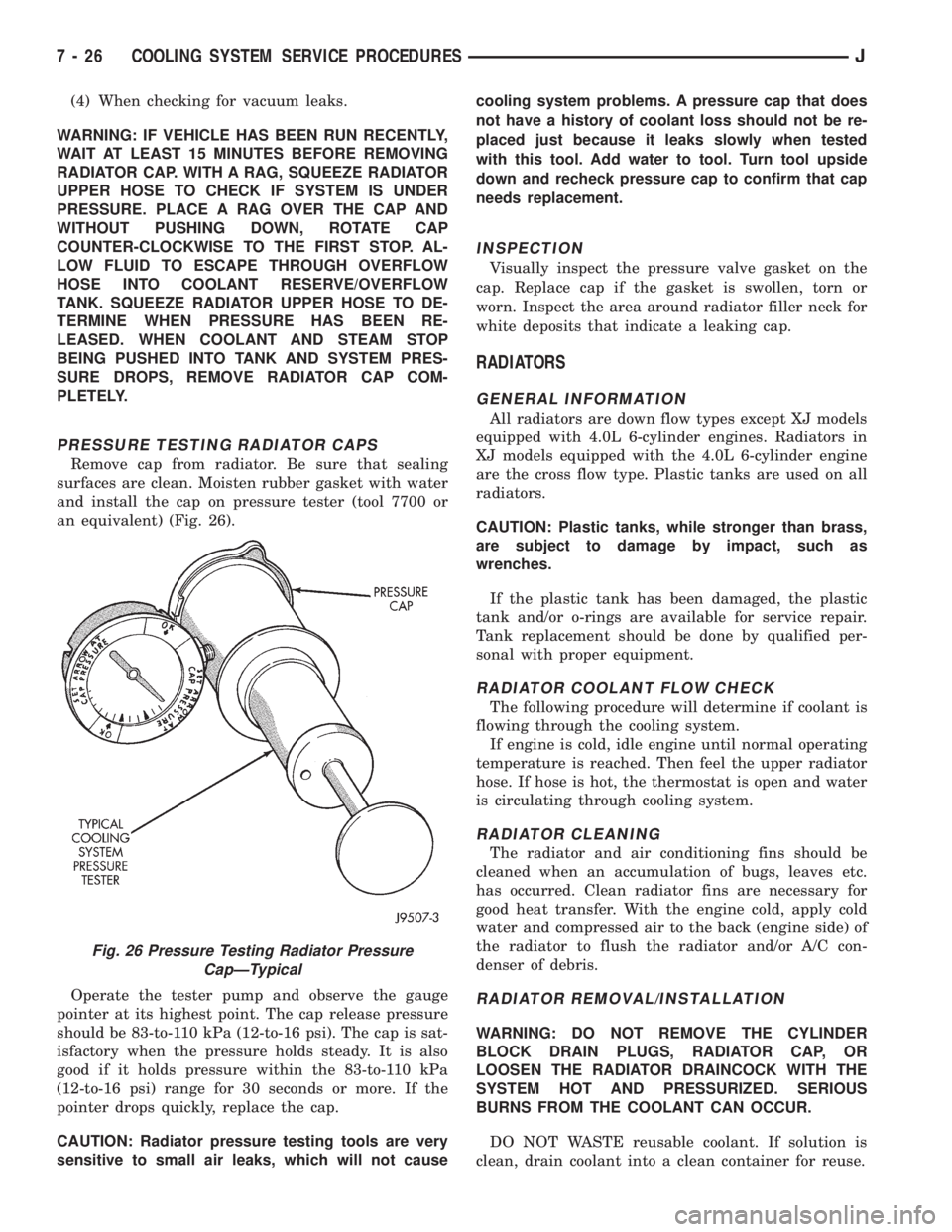
and install the cap on pressure tester (tool 7700 or
an equivalent) (Fig. 26).
Operate the tester pump and observe the gauge
pointer at its highest point. The cap release pressure
should be 83-to-110 kPa (12-to-16 psi). The cap is sat-
isfactory when the pressure holds steady. It is also
good if it holds pressure within the 83-to-110 kPa
(12-to-16 psi) range for 30 seconds or more. If the
pointer drops quickly, replace the cap.
CAUTION: Radiator pressure testing tools are very
sensitive to small air leaks, which will not causecooling system problems. A pressure cap that does
not have a history of coolant loss should not be re-
placed just because it leaks slowly when tested
with this tool. Add water to tool. Turn tool upside
down and recheck pressure cap to confirm that cap
needs replacement.
INSPECTION
Visually inspect the pressure valve gasket on the
cap. Replace cap if the gasket is swollen, torn or
worn. Inspect the area around radiator filler neck for
white deposits that indicate a leaking cap.
RADIATORS
GENERAL INFORMATION
All radiators are down flow types except XJ models
equipped with 4.0L 6-cylinder engines. Radiators in
XJ models equipped with the 4.0L 6-cylinder engine
are the cross flow type. Plastic tanks are used on all
radiators.
CAUTION: Plastic tanks, while stronger than brass,
are subject to damage by impact, such as
wrenches.
If the plastic tank has been damaged, the plastic
tank and/or o-rings are available for service repair.
Tank replacement should be done by qualified per-
sonal with proper equipment.
RADIATOR COOLANT FLOW CHECK
The following procedure will determine if coolant is
flowing through the cooling system.
If engine is cold, idle engine until normal operating
temperature is reached. Then feel the upper radiator
hose. If hose is hot, the thermostat is open and water
is circulating through cooling system.
RADIATOR CLEANING
The radiator and air conditioning fins should be
cleaned when an accumulation of bugs, leaves etc.
has occurred. Clean radiator fins are necessary for
good heat transfer. With the engine cold, apply cold
water and compressed air to the back (engine side) of
the radiator to flush the radiator and/or A/C con-
denser of debris.
RADIATOR REMOVAL/INSTALLATION
WARNING: DO NOT REMOVE THE CYLINDER
BLOCK DRAIN PLUGS, RADIATOR CAP, OR
LOOSEN THE RADIATOR DRAINCOCK WITH THE
SYSTEM HOT AND PRESSURIZED. SERIOUS
BURNS FROM THE COOLANT CAN OCCUR.
DO NOT WASTE reusable coolant. If solution is
clean, drain coolant into a clean container for reuse.
Fig. 26 Pressure Testing Radiator Pressure
CapÐTypical
7 - 26 COOLING SYSTEM SERVICE PROCEDURESJ
Page 1218 of 2198
FUEL DELIVERY SYSTEM
INDEX
page page
Fuel Filter................................ 9
Fuel Pressure Leak Down Test................ 8
Fuel Pressure Release Procedure.............. 6
Fuel Pump Capacity Test.................... 7
Fuel Pump Electrical Control.................. 5Fuel Pump Module......................... 3
Fuel System Pressure Test................... 6
Fuel Tubes/Lines/Hoses and Clamps............ 9
Quick-Connect Fittings..................... 10
FUEL PUMP MODULE
The fuel pump module is installed in the top of the
fuel tank. The fuel pump module contains the follow-
ing components:
²Electric fuel pump
²Fuel pump reservoir
²In-tank fuel filter
²Fuel gauge sending unit
²Fuel supply and return tube connections
The fuel pump used on all vehicles is a turbine
type pump. It is driven by a permanent magnet 12
volt electric motor that is immersed in the fuel tank.
The electrical pump is integral with the fuel sender
unit. The pump/sender assembly is installed inside
the fuel tank.
The fuel pump has a check valve at the outlet end
that consists of a ball held against a seat by force ap-
plied from a spring. When the pump is operating,
fuel pressure overcomes spring pressure and forces
the ball off its seat, allowing fuel to flow. When the
pump is not operating, spring pressure forces the ball
back against the seat preventing fuel backflow
through the pump.
Fuel system pressure is maintained at approxi-
mately 214 kPa (31 psi). This is when the pump is
operating and vacuum is supplied to the fuel pres-
sure regulator. If vacuum is not supplied to the pres-
sure regulator, fuel pressure will be approximately
55-69 kPa (8-10 psi) higher. This may be due to a
broken or clogged vacuum line. When the fuel pump
is not operating, fuel system pressure of 131-269 kPa
(19-39 psi) is maintained for approximately 2 to 6
hours. This is done by the fuel pump outlet check
valve and the vacuum assisted fuel pressure regula-
tor.
REMOVALÐXJ MODELS
The fuel pump/gauge sender unit assembly can be
removed from the fuel tank without removing the
tank from the vehicle.
WARNING: THE FUEL SYSTEM IS UNDER A CON-
STANT PRESSURE (EVEN WITH THE ENGINE OFF).
BEFORE SERVICING THE FUEL PUMP MODULE,
THE FUEL SYSTEM PRESSURE MUST BE RE-LEASED. REFER TO THE FUEL PRESSURE RE-
LEASE PROCEDURE IN THIS GROUP.
WARNING: EXTINGUISH ALL TOBACCO SMOKING
PRODUCTS BEFORE SERVICING THE FUEL SYS-
TEM. KEEP OPEN FLAME AWAY FROM FUEL SYS-
TEM COMPONENTS.
(1) Remove fuel filler cap. Perform the Fuel Pres-
sure Release Procedure as outlined in this group.
(2) Disconnect negative battery cable.
(3) Using an approved portable gasoline siphon/
storage tank, drain fuel tank until fuel level is below
one quarter (1/4) full.
(4) Raise and support vehicle.
WARNING: WRAP SHOP TOWELS AROUND FUEL
HOSES TO ABSORB ANY FUEL SPILLAGE DURING
FUEL TANK REMOVAL.
(5) Disconnect fuel vent supply and return tubes
from fittings on fuel pump module.
(6) Disconnect fuel pump module electrical harness
connector from main harness.
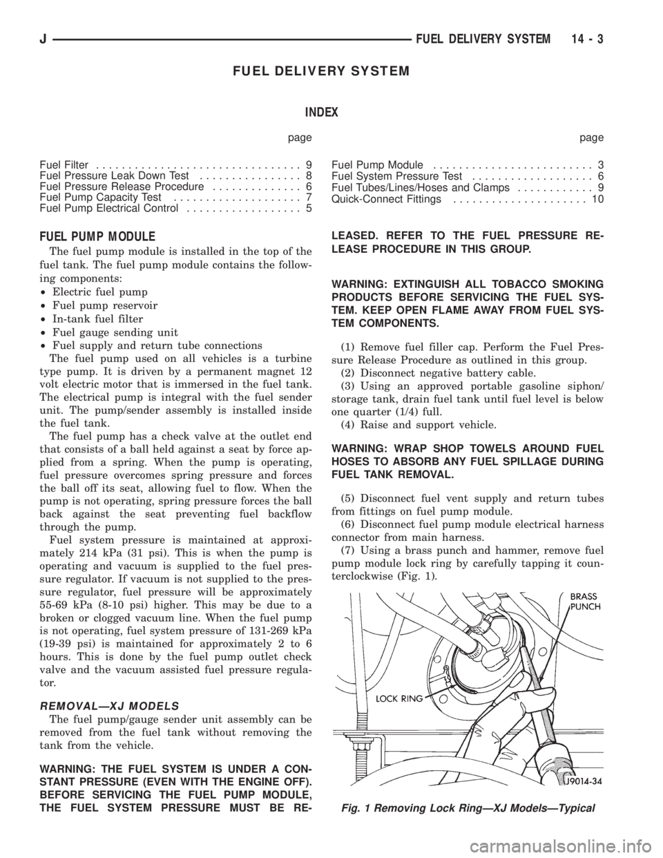
(7) Using a brass punch and hammer, remove fuel
pump module lock ring by carefully tapping it coun-
terclockwise (Fig. 1).
Fig. 1 Removing Lock RingÐXJ ModelsÐTypical
JFUEL DELIVERY SYSTEM 14 - 3
Page 1228 of 2198
FUEL TANKS
INDEX
page page
Fuel Gauge Sending Unit................... 16
Fuel Tank............................... 13
Fuel Tank Capacities....................... 13
Fuel Tank Filler Tube Cap................... 13Fuel Tank Pressure Relief/Rollover Valve........ 16
General Information....................... 13
Heat Shields............................. 13
No-Lead Fuel Tank Filler Tube................ 13
GENERAL INFORMATION
All XJ and YJ models pass a full 360 degree roll-
over test without fuel leakage. To accomplish this,
fuel and vapor flow controls are required for all fuel
tank connections.
All models are equipped with a pressure relief/roll-
over valve mounted in the top of the fuel tank. The
return line from the fuel pump to the fuel tank con-
tains a one-way check valve.
An evaporative control system prevents raw fuel
vapor from escaping into the atmosphere. Fuel va-
pors from the fuel tank are collected in the EVAP
canister. When the engine is operating, the vapors
are drawn into the intake manifold to be used in
combustion. Refer to Group 25, Emission Control
System for more information.
Inspect all hose/tube connections for completeness.
Be sure that leaks are not present. Replace any hose
that is cracked, scuffed, swelled, has rubbed against
other vehicle components or shows any other sign of
wear that could lead to failure. If it is necessary to
replace a hose, only hose marked EFM/EFI may be
used.
When installing hoses, be sure that they are routed
away from contact with other vehicle components.
The hose clamps used on fuel injected vehicles are
of a special rolled edge construction to prevent the
edge of the clamp from cutting into the hose. Only
these rolled edge type clamps may be used on this
system. Other types of clamps may cut into the hoses
and cause high-pressure fuel leaks.
FUEL TANK CAPACITIES
Refer to the Specifications section at the end of this
group.
NO-LEAD FUEL TANK FILLER TUBE
All vehicles are designed to operate using Unleaded
fuels. The diameter of the opening in the fuel tank
filler neck is sized to only accept unleaded fuel noz-
zles. Gasoline station pumps for unleaded and leaded
fuels have different size nozzles. Leaded fuel nozzles
are larger in diameter than unleaded nozzles. The
fuel tank filler neck opening is also equipped with adeflector, which the smaller unleaded nozzle pushes
back upon entering the filler neck. The deflector will
prevent the larger diameter leaded fuel nozzles from
entering the filler neck and will deflect fuel away
from the filler neck. This happens if filling of the
tank with leaded fuel is attempted.
A label is attached to the instrument panel under
the fuel gauge that reads UNLEADED FUEL ONLY
as a reminder to the driver. A similar label is located
near the fuel tank filler.
FUEL TANK FILLER TUBE CAP
The loss of any fuel or vapor out of the filler neck
is prevented by the use of a safety filler cap. This
will release only under pressure of 10.9 to 13.45 kPa
(1.58 to 1.95 psi). The vacuum release is between .97
and 2.0 kPa (.14 and .29 psi). This cap must be re-
placed by a similar unit if replacement is necessary.
CAUTION: Remove the fuel tank filler tube cap prior
to removing or repairing fuel lines to relieve fuel
tank pressure.
HEAT SHIELDS
The sheet metal heat shields may have to be re-
moved when servicing the fuel tank, fuel lines or va-
por vent line. The heat shields must be installed to
protect the lines and tank from the heat of the ex-
haust system. Refer to Group 11, Exhaust System
and Intake Manifold for proper installation.
FUEL TANK
WARNING: THE FUEL SYSTEM IS UNDER CON-
STANT FUEL PRESSURE (EVEN WITH THE ENGINE
OFF) OF APPROXIMATELY 131-269 KPA (19-39 PSI).
THIS PRESSURE MUST BE RELEASED BEFORE
SERVICING FUEL TANK.
REMOVALÐXJ MODELS
Perform the preceding Fuel System Pressure Re-
lease Procedure.
(1) Disconnect negative battery cable.
JFUEL TANKS 14 - 13
Page 1229 of 2198
(2) Remove the fuel filler cap. Using an approved por-
table gasoline siphon/storage tank, drain fuel tank.
(3) Raise and support vehicle.
(4) Disconnect fuel fill hose and fill vent hose from
filler neck (Fig. 1).
(5) Disconnect fuel pump module wire connector.
Remove tie straps securing connector harness to fuel
supply and return tubes.
WARNING: WRAP SHOP TOWELS AROUND FUEL
HOSES TO ABSORB ANY FUEL SPILLAGE DURING
FUEL TANK REMOVAL.
(6) Disconnect fuel tank vent hose from vent tube.
(7) Disconnect fuel supply and return hoses from
tubes.
(8) If equipped, remove skid plate (Fig. 2).
(9) Remove fuel tank shield (Fig. 3).
(10) Center a transmission jack under the fuel tank.
(11) Remove support strap nuts. Move straps away
from tank (Fig. 3).
(12) Lower fuel tank on transmission jack.
INSTALLATIONÐXJ MODELS
(1) Raise fuel tank into position. Connect fuel fill
hose and vent hose to filler neck and tighten clamps.
(2) Wrap support straps around tank and over studs.
Tighten strap nuts to 11.3 Nzm (100 in. lbs.) torque.
(3) Remove transmission jack.
(4) Install tank shield.
(5) If equipped, install tank skid plate.
(6) Connect vent hose to vent tube.
(7) Connect fuel supply hose to supply tube and
fuel return hose to return tube. Tighten hose clamps.(8) Connect fuel pump module wire connector to
harness connector. Secure fuel pump module wire
harness to fuel tubes with tie straps.
(9) Lower vehicle.
(10) Fill fuel tank. Install filler cap.
(11) Connect negative battery cable to battery.
(12) Start vehicle and inspect for leaks.REMOVALÐYJ MODELS
WARNING: EXTINGUISH ALL TOBACCO SMOKING
PRODUCTS BEFORE SERVICING THE FUEL SYS-
TEM. KEEP OPEN FLAME AWAY FROM FUEL SYS-
TEM COMPONENTS.
Fig. 1 Filler Neck HosesÐXJ Models
Fig. 2 Skid PlateÐXJ Models
Fig. 3 Fuel Tank Remove/InstallÐXJ Models
14 - 14 FUEL TANKSJ
Page 1937 of 2198
EMISSION CONTROLS
INDEX
page page
Crankcase Ventilation System................. 5
EVAP (Evaporation) Control System............ 4
EVAP Canister............................ 4Fuel Tank Filler Tube Cap.................... 4
Oxygen (O2S) Sensor....................... 6
Pressure Relief/Rollover Valve................. 6
EVAP (EVAPORATION) CONTROL SYSTEM
GENERAL INFORMATION
The function of the EVAP control system is to pre-
vent the emissions of gasoline vapors from the fuel
tank into the atmosphere. When fuel evaporates in
the fuel tank, the vapors pass through vent hoses or
tubes to a carbon filled EVAP canister. They are tem-
porarily held in the canister until they can be drawn
into the intake manifold when the engine is running.
The EVAP canister is a feature on all models for
the storage of fuel vapors from the fuel tank.
The hoses used in this system are specially
manufactured. If replacement becomes neces-
sary, it is important to use only fuel resistant
hose.
EVAP CANISTER
A sealed, maintenance free, EVAP canister is used
on all vehicles. On XJ models, the EVAP canister is
located in the engine compartment on the passenger
side frame rail (Fig. 4). On YJ models, the EVAP can-
ister is located in the engine compartment on the
dash panel and below the brake master cylinder (Fig.
5). The EVAP canister is filled with granules of an
activated carbon mixture. Fuel vapors entering the
EVAP canister are absorbed by the charcoal granules.
CANISTER OPERATION
Vacuum is used to control and operate the
EVAP canister. No electrical circuitry is used to
control or operate the EVAP system.
The EVAP canister is equipped with a vacuum con-
trolled purge shutoff switch (orifice) (Figs. 4 or 5)
that controls canister purge operation. The switch is
open when manifold vacuum is applied to it. When
the engine is operating, the EVAP canister purge
function draws fresh air through the top of the can-
ister. This causes the stored vapors to be drawn out
of the canister and into the airstream in the air
cleaner snorkel (Fig. 6).
The air cleaner contains a venturi in the air
cleaner cover used as a purge line vacuum source
(Fig. 6). The venturi effect increases the speed of the
intake air flowing by the slots in the venturi wall.
This creates a low pressure area around the slots.
When the purge shutoff switch is open, vapors from
the canister are drawn through slots and into the air-
stream flowing through the venturi (Fig. 7). The va-
pors pass through the intake manifold into the
engine combustion chambers where they are con-
sumed during engine combustion.
FUEL TANK FILLER TUBE CAP
The fuel tank filler tube cap (fuel tank cap) incor-
porates a two-way pressure/relief valve that is closed
to atmosphere during normal operating conditions.Fig. 4 EVAP Canister LocationÐXJ Models
Fig. 5 EVAP Canister LocationÐYJ Models
25 - 4 EMISSION CONTROL SYSTEMSJ