Page 1651 of 2198
(45) Install overdrive support in case. Use two long
bolts to help align and guide support into position
(Fig. 37).
(46) Install overdrive support snap ring with Snap
Ring Plier Tool 7540 (Fig. 38). Chamfered side of
snap ring faces up and toward case front.Snap ring
ends must be aligned with case opening with
ring ends approximately 24 mm (0.94 in.) from
centerline of case opening.(47) Install and tighten overdrive support bolts to
25 Nzm (19 ft-lbs) torque (Fig. 39).
(48) Check output shaft end play with dial indica-
tor (Fig. 40). End play should be 0.27 - 0.86 mm
(0.0106 - 0.0339 in.).
(49) If output shaft end play is incorrect, one or
more of installed components is not seated. Reassem-
ble as necessary and check end play again.
Fig. 37 Installing Overdrive Support
Fig. 38 Installing Overdrive Support Snap Ring
Fig. 39 Installing Overdrive Support Bolts
Fig. 40 Checking Output Shaft End Play
21 - 274 AW-4 TRANSMISSION OVERHAULJ
Page 1654 of 2198
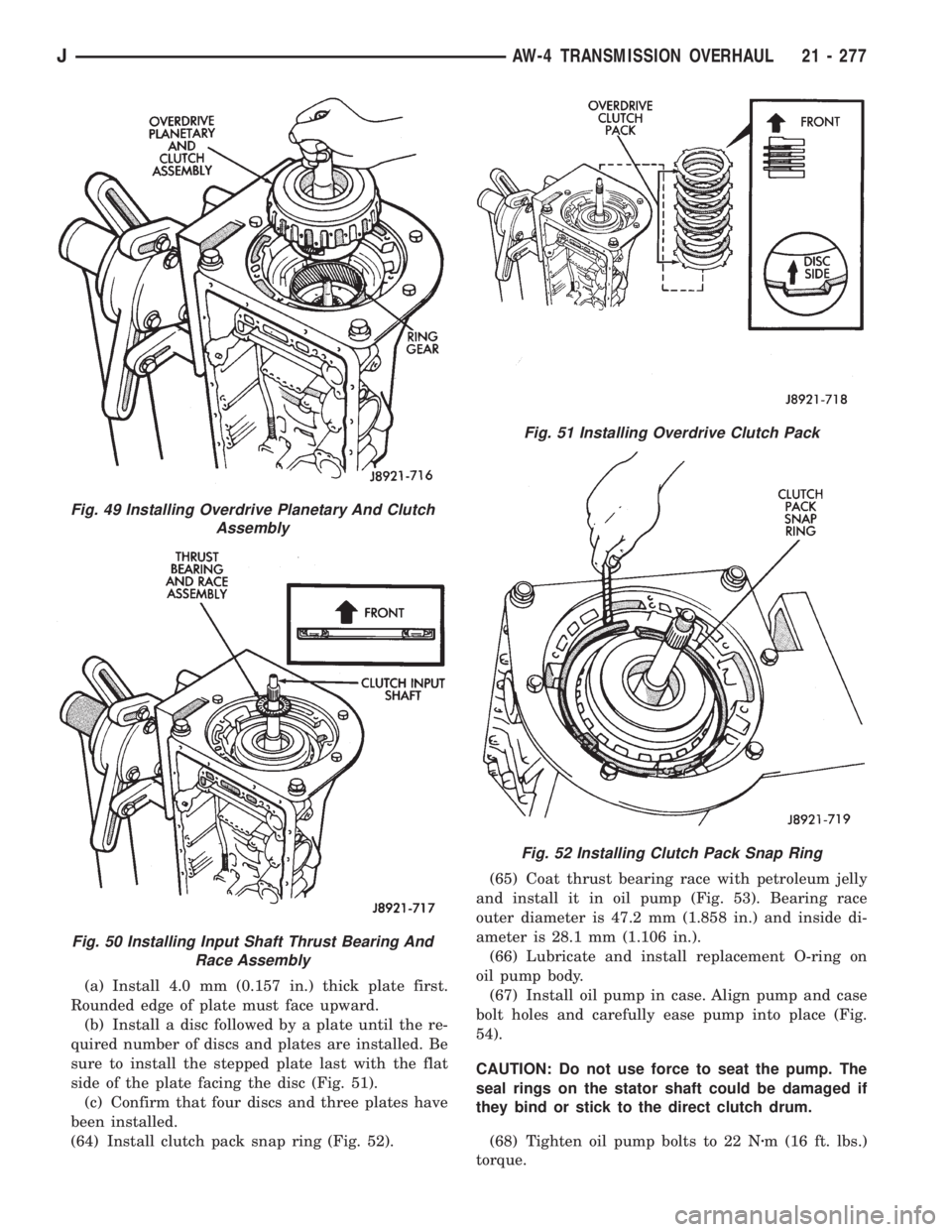
(a) Install 4.0 mm (0.157 in.) thick plate first.
Rounded edge of plate must face upward.
(b) Install a disc followed by a plate until the re-
quired number of discs and plates are installed. Be
sure to install the stepped plate last with the flat
side of the plate facing the disc (Fig. 51).
(c) Confirm that four discs and three plates have
been installed.
(64) Install clutch pack snap ring (Fig. 52).(65) Coat thrust bearing race with petroleum jelly
and install it in oil pump (Fig. 53). Bearing race
outer diameter is 47.2 mm (1.858 in.) and inside di-
ameter is 28.1 mm (1.106 in.).
(66) Lubricate and install replacement O-ring on
oil pump body.
(67) Install oil pump in case. Align pump and case
bolt holes and carefully ease pump into place (Fig.
54).
CAUTION: Do not use force to seat the pump. The
seal rings on the stator shaft could be damaged if
they bind or stick to the direct clutch drum.
(68) Tighten oil pump bolts to 22 Nzm (16 ft. lbs.)
torque.
Fig. 49 Installing Overdrive Planetary And Clutch
Assembly
Fig. 50 Installing Input Shaft Thrust Bearing And
Race Assembly
Fig. 51 Installing Overdrive Clutch Pack
Fig. 52 Installing Clutch Pack Snap Ring
JAW-4 TRANSMISSION OVERHAUL 21 - 277
Page 1659 of 2198
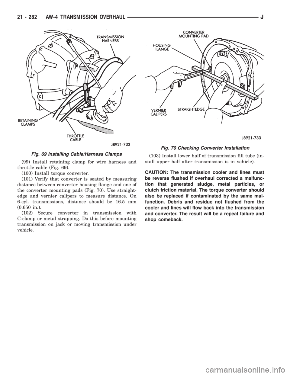
(99) Install retaining clamp for wire harness and
throttle cable (Fig. 69).
(100) Install torque converter.
(101) Verify that converter is seated by measuring
distance between converter housing flange and one of
the converter mounting pads (Fig. 70). Use straight-
edge and vernier calipers to measure distance. On
6-cyl. transmissions, distance should be 16.5 mm
(0.650 in.).
(102) Secure converter in transmission with
C-clamp or metal strapping. Do this before mounting
transmission on jack or moving transmission under
vehicle.(103) Install lower half of transmission fill tube (in-
stall upper half after transmission is in vehicle).
CAUTION: The transmission cooler and lines must
be reverse flushed if overhaul corrected a malfunc-
tion that generated sludge, metal particles, or
clutch friction material. The torque converter should
also be replaced if contaminated by the same mal-
function. Debris and residue not flushed from the
cooler and lines will flow back into the transmission
and converter. The result will be a repeat failure and
shop comeback.
Fig. 69 Installing Cable/Harness Clamps
Fig. 70 Checking Converter Installation
21 - 282 AW-4 TRANSMISSION OVERHAULJ
Page 1672 of 2198
FRONT CASE ASSEMBLY
(1) Lubricate components with automatic transmis-
sion fluid (or petroleum jelly where indicated) during
assembly.
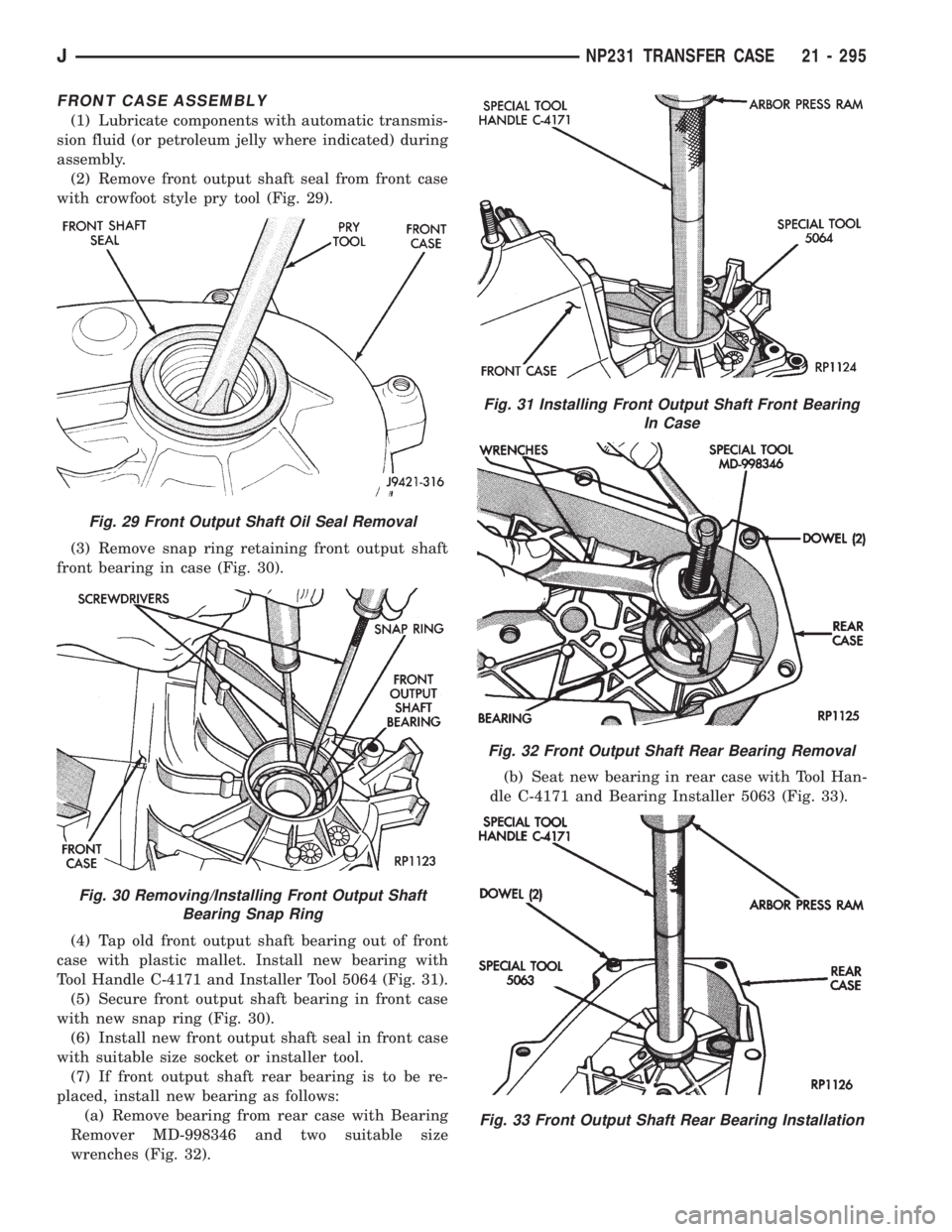
(2) Remove front output shaft seal from front case
with crowfoot style pry tool (Fig. 29).
(3) Remove snap ring retaining front output shaft
front bearing in case (Fig. 30).
(4) Tap old front output shaft bearing out of front
case with plastic mallet. Install new bearing with
Tool Handle C-4171 and Installer Tool 5064 (Fig. 31).
(5) Secure front output shaft bearing in front case
with new snap ring (Fig. 30).
(6) Install new front output shaft seal in front case
with suitable size socket or installer tool.
(7) If front output shaft rear bearing is to be re-
placed, install new bearing as follows:
(a) Remove bearing from rear case with Bearing
Remover MD-998346 and two suitable size
wrenches (Fig. 32).(b) Seat new bearing in rear case with Tool Han-
dle C-4171 and Bearing Installer 5063 (Fig. 33).
Fig. 29 Front Output Shaft Oil Seal Removal
Fig. 30 Removing/Installing Front Output Shaft
Bearing Snap Ring
Fig. 31 Installing Front Output Shaft Front Bearing
In Case
Fig. 32 Front Output Shaft Rear Bearing Removal
Fig. 33 Front Output Shaft Rear Bearing Installation
JNP231 TRANSFER CASE 21 - 295
Page 1673 of 2198
(8) Remove input gear bearing from front case
with Tool Handle C-4171 and Tool C-4210, 7828, or
5062. Use tool that is best fit in bearing (Fig. 34).
(9) Turn front case over.
(10) Start bearing in case by hand. Then seat bear-
ing with Tools C-4171 and C-4210, or 7828 until snap
ring seats against case surface (Fig. 35).
INPUT AND LOW RANGE GEAR ASSEMBLY
AND INSTALLATION
(1) Remove mainshaft pilot bearing from input
gear with Tool MD-998346, or similar tool as follows:
(a) Turn puller tool bolt until jaws retract
enough to fit into bearing (Fig. 36).
(b) Insert puller bolt and jaws into bearing. Then
turn puller bolt clockwise so ramp on bolt spreads
jaws forcing them under bearing (Fig. 37).
Fig. 34 Input Gear Bearing Removal
Fig. 35 Input Gear Bearing Installation
Fig. 36 Puller Jaws In Retracted Position
Fig. 37 Puller Bolt And Jaws Seated Under Needle
Bearing
21 - 296 NP231 TRANSFER CASEJ
Page 1674 of 2198
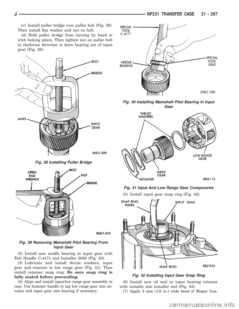
(c) Install puller bridge over puller bolt (Fig. 38).
Then install flat washer and nut on bolt.
(d) Hold puller bridge from turning by hand or
with locking pliers. Then tighten nut on puller bolt
in clockwise direction to draw bearing out of input
gear (Fig. 39).
(2) Install new needle bearing in input gear with
Tool Handle C-4171 and Installer 5065 (Fig. 40).
(3) Lubricate and install thrust washers, input
gear and retainer in low range gear (Fig. 41). Then
install retainer snap ring.Be sure snap ring is
fully seated before proceeding.
(4) Align and install input/low range gear assembly in
case. Use hammer handle to tap low range gear into an-
nulus and input gear into bearing if necessary.
(5) Install input gear snap ring (Fig. 42).
(6) Install new oil seal in input bearing retainer
with suitable size installer tool (Fig. 43).
(7) Apply 3 mm (1/8 in.) wide bead of Mopar Gas-
Fig. 38 Installing Puller Bridge
Fig. 39 Removing Mainshaft Pilot Bearing From
Input Gear
Fig. 40 Installing Mainshaft Pilot Bearing In Input
Gear
Fig. 41 Input And Low Range Gear Components
Fig. 42 Installing Input Gear Snap Ring
JNP231 TRANSFER CASE 21 - 297
Page 1676 of 2198
(2) Install shift sector in the case (Fig. 48).
(3) Install range lever and lever attaching nut on
shift sector. Tighten attaching nut to 30 Nzm (22 ft.
lbs.) torque.
(4) Install detent plunger, spring and plug (Fig.
49). Tighten plug to 20 Nzm (15 ft. lbs.) torque.
(5) Inspect pads on range fork (Fig. 50). Be sure
pads are secure and in position. Replace fork as an
assembly if pads are worn through, or broken.
(6) Assemble range fork and shift hub (Fig. 51).
(7) Engage range fork pin in shift sector slot (Fig.
52).
(8) Insert shift hub in low range gear. Be sure hub
is fully seated.
Fig. 48 Shift Sector Installation
Fig. 49 Installing Detent Plunger, Spring And Plug
Fig. 50 Range Fork Pad Locations
Fig. 51 Assembling Range Fork And Shift Hub
Fig. 52 Seating Range Fork Pin In Shift Sector Slot
JNP231 TRANSFER CASE 21 - 299
Page 1677 of 2198
MAINSHAFT ASSEMBLY
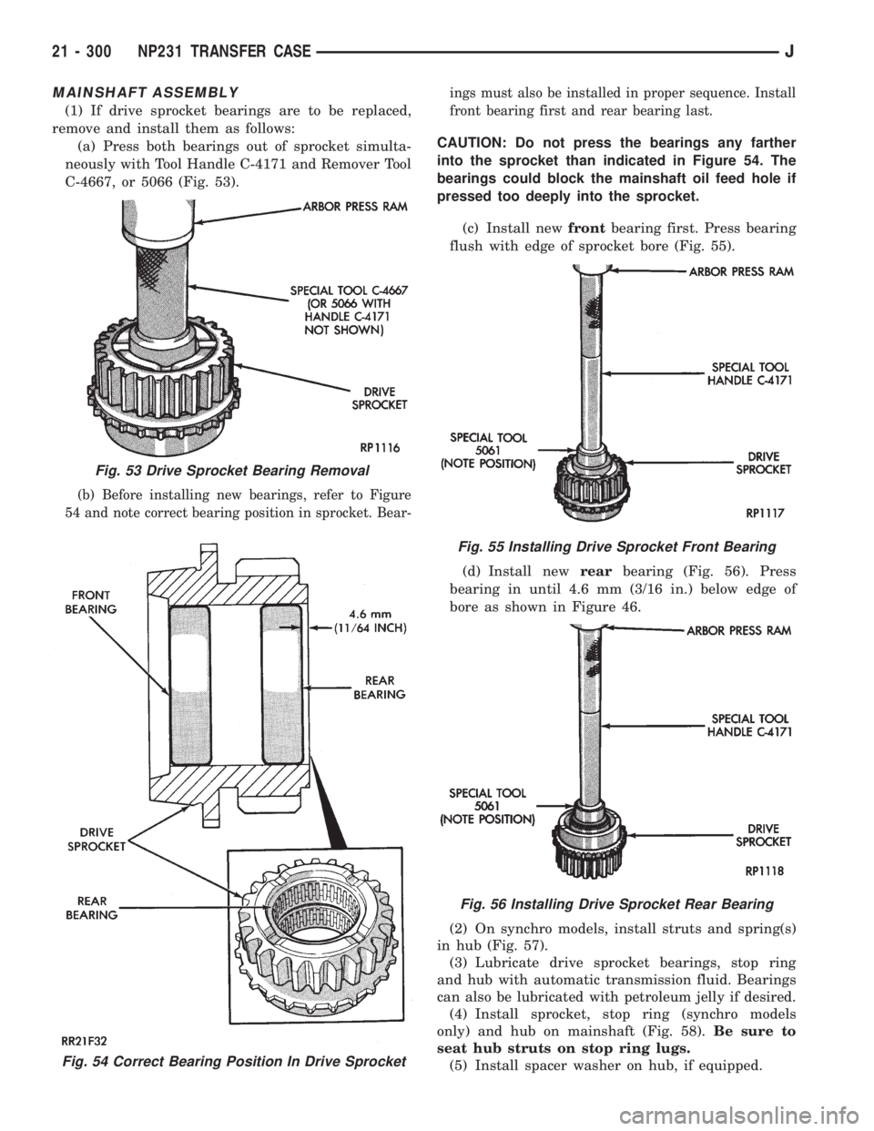
(1) If drive sprocket bearings are to be replaced,
remove and install them as follows:
(a) Press both bearings out of sprocket simulta-
neously with Tool Handle C-4171 and Remover Tool
C-4667, or 5066 (Fig. 53).
(b) Before installing new bearings, refer to Figure
54 and note correct bearing position in sprocket. Bear-ings must also be installed in proper sequence. Install
front bearing first and rear bearing last.
CAUTION: Do not press the bearings any farther
into the sprocket than indicated in Figure 54. The
bearings could block the mainshaft oil feed hole if
pressed too deeply into the sprocket.
(c) Install newfrontbearing first. Press bearing
flush with edge of sprocket bore (Fig. 55).
(d) Install newrearbearing (Fig. 56). Press
bearing in until 4.6 mm (3/16 in.) below edge of
bore as shown in Figure 46.
(2) On synchro models, install struts and spring(s)
in hub (Fig. 57).
(3) Lubricate drive sprocket bearings, stop ring
and hub with automatic transmission fluid. Bearings
can also be lubricated with petroleum jelly if desired.
(4) Install sprocket, stop ring (synchro models
only) and hub on mainshaft (Fig. 58).Be sure to
seat hub struts on stop ring lugs.
(5) Install spacer washer on hub, if equipped.
Fig. 54 Correct Bearing Position In Drive Sprocket
Fig. 53 Drive Sprocket Bearing Removal
Fig. 55 Installing Drive Sprocket Front Bearing
Fig. 56 Installing Drive Sprocket Rear Bearing
21 - 300 NP231 TRANSFER CASEJ