INSTALLATION
(1) Assemble exhaust pipe to manifold and cata-
lytic converter loosely to permit proper alignment of
all parts.
(2) Use a new clamp and tighten the nuts to 61
Nzm (45 ft. lbs.) torque.
(3) Connect the exhaust pipe to the engine exhaust
manifold. Install a new seal between the exhaust
manifold and the exhaust pipe (4.0L engine, only).
Tighten the nuts to 31 Nzm (23 ft. lbs.) torque (Fig.
1).
(3) Install the rear crossmember. Tighten the
crossmember-to-sill bolts to 41 Nzm (30 ft. lbs.)
torque. Remove the support from the transmission.
(4) Coat the oxygen sensor with anti-seize com-
pound. Install the sensor and tighten the nut to 48
Nzm (35 ft. lbs.) torque.
(5) Lower the vehicle.
(6) Start the engine and inspect for exhaust leaks
and exhaust system contact with the body panels.
Adjust the alignment, if needed.
EXHAUST PIPEÐYJ VEHICLES
WARNING: IF TORCHES ARE USED WHEN WORK-
ING ON THE EXHAUST SYSTEM, DO NOT ALLOW
THE FLAME NEAR THE FUEL LINES.
REMOVAL
(1) Raise and support the vehicle.
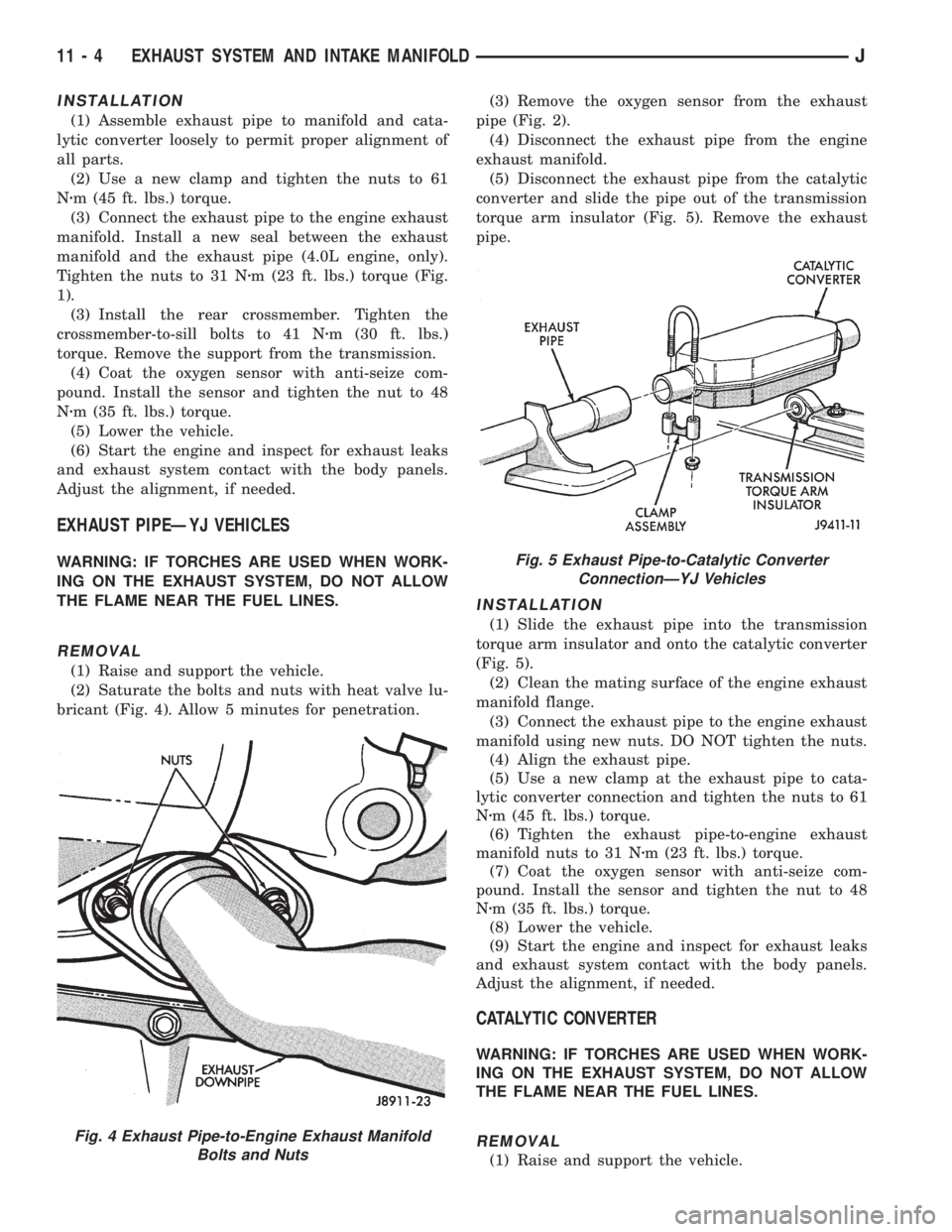
(2) Saturate the bolts and nuts with heat valve lu-
bricant (Fig. 4). Allow 5 minutes for penetration.(3) Remove the oxygen sensor from the exhaust
pipe (Fig. 2).
(4) Disconnect the exhaust pipe from the engine
exhaust manifold.
(5) Disconnect the exhaust pipe from the catalytic
converter and slide the pipe out of the transmission
torque arm insulator (Fig. 5). Remove the exhaust
pipe.
INSTALLATION
(1) Slide the exhaust pipe into the transmission
torque arm insulator and onto the catalytic converter
(Fig. 5).
(2) Clean the mating surface of the engine exhaust
manifold flange.
(3) Connect the exhaust pipe to the engine exhaust
manifold using new nuts. DO NOT tighten the nuts.
(4) Align the exhaust pipe.
(5) Use a new clamp at the exhaust pipe to cata-
lytic converter connection and tighten the nuts to 61
Nzm (45 ft. lbs.) torque.
(6) Tighten the exhaust pipe-to-engine exhaust
manifold nuts to 31 Nzm (23 ft. lbs.) torque.
(7) Coat the oxygen sensor with anti-seize com-
pound. Install the sensor and tighten the nut to 48
Nzm (35 ft. lbs.) torque.
(8) Lower the vehicle.
(9) Start the engine and inspect for exhaust leaks
and exhaust system contact with the body panels.
Adjust the alignment, if needed.
CATALYTIC CONVERTER
WARNING: IF TORCHES ARE USED WHEN WORK-
ING ON THE EXHAUST SYSTEM, DO NOT ALLOW
THE FLAME NEAR THE FUEL LINES.
REMOVAL
(1) Raise and support the vehicle.
Fig. 4 Exhaust Pipe-to-Engine Exhaust Manifold
Bolts and Nuts
Fig. 5 Exhaust Pipe-to-Catalytic Converter
ConnectionÐYJ Vehicles
11 - 4 EXHAUST SYSTEM AND INTAKE MANIFOLDJ
INTAKE MANIFOLD
Refer to Group 11, Exhaust System and Intake
Manifold for removal/installation procedures.
MANIFOLD ABSOLUTE PRESSURE (MAP) SENSOR
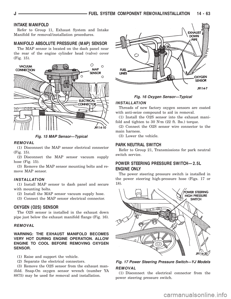
The MAP sensor is located on the dash panel near
the rear of the engine cylinder head (valve) cover
(Fig. 15).
REMOVAL
(1) Disconnect the MAP sensor electrical connector
(Fig. 15).
(2) Disconnect the MAP sensor vacuum supply
hose (Fig. 15).
(3) Remove the MAP sensor mounting bolts and re-
move MAP sensor.
INSTALLATION
(1) Install MAP sensor to dash panel and secure
with mounting bolts.
(2) Install the MAP sensor vacuum supply hose.
(3) Connect the MAP sensor electrical connector.
OXYGEN (O2S) SENSOR
The O2S sensor is installed in the exhaust down
pipe just below the exhaust manifold flange (Fig. 16).
REMOVAL
WARNING: THE EXHAUST MANIFOLD BECOMES
VERY HOT DURING ENGINE OPERATION. ALLOW
ENGINE TO COOL BEFORE REMOVING OXYGEN
SENSOR.
(1) Raise and support the vehicle.
(2) Separate the electrical connectors.
(3) Remove the O2S sensor from the exhaust man-
ifold. Snap-On oxygen sensor wrench (number YA
8875) may be used for removal and installation.
INSTALLATION
Threads of new factory oxygen sensors are coated
with anti-seize compound to aid in removal.
(1) Install the O2S sensor into the exhaust mani-
fold and tighten to 30 Nzm (22 ft. lbs.) torque.
(2) Connect the O2S sensor wire connector to the
main harness.
(3) Lower the vehicle.
PARK NEUTRAL SWITCH
Refer to Group 21, Transmissions for park neutral
switch service.
POWER STEERING PRESSURE SWITCHÐ2.5L
ENGINE ONLY
The power steering pressure switch is installed in
the power steering high-pressure hose (Figs. 17 or
18).
REMOVAL
(1) Disconnect the electrical connector from the
power steering pressure switch.
Fig. 15 MAP SensorÐTypical
Fig. 16 Oxygen SensorÐTypical
Fig. 17 Power Steering Pressure SwitchÐYJ Models
JFUEL SYSTEM COMPONENT REMOVAL/INSTALLATION 14 - 63