Page 1567 of 2198
(4) Inspect pistons, springs and piston bores. Re-
place worn damaged pistons. Replace broken, col-
lapsed or distorted springs. Replace case if piston
bores are damaged.
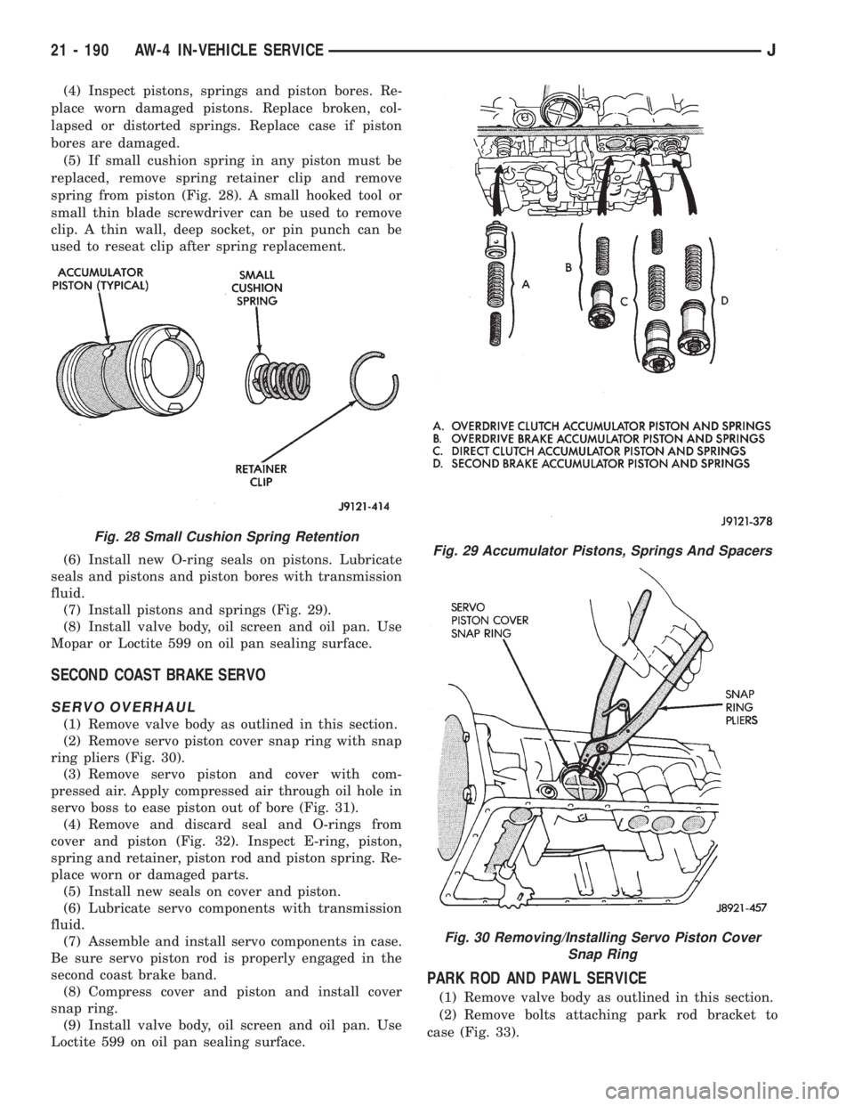
(5) If small cushion spring in any piston must be
replaced, remove spring retainer clip and remove
spring from piston (Fig. 28). A small hooked tool or
small thin blade screwdriver can be used to remove
clip. A thin wall, deep socket, or pin punch can be
used to reseat clip after spring replacement.
(6) Install new O-ring seals on pistons. Lubricate
seals and pistons and piston bores with transmission
fluid.
(7) Install pistons and springs (Fig. 29).
(8) Install valve body, oil screen and oil pan. Use
Mopar or Loctite 599 on oil pan sealing surface.
SECOND COAST BRAKE SERVO
SERVO OVERHAUL
(1) Remove valve body as outlined in this section.
(2) Remove servo piston cover snap ring with snap
ring pliers (Fig. 30).
(3) Remove servo piston and cover with com-
pressed air. Apply compressed air through oil hole in
servo boss to ease piston out of bore (Fig. 31).
(4) Remove and discard seal and O-rings from
cover and piston (Fig. 32). Inspect E-ring, piston,
spring and retainer, piston rod and piston spring. Re-
place worn or damaged parts.
(5) Install new seals on cover and piston.
(6) Lubricate servo components with transmission
fluid.
(7) Assemble and install servo components in case.
Be sure servo piston rod is properly engaged in the
second coast brake band.
(8) Compress cover and piston and install cover
snap ring.
(9) Install valve body, oil screen and oil pan. Use
Loctite 599 on oil pan sealing surface.
PARK ROD AND PAWL SERVICE
(1) Remove valve body as outlined in this section.
(2) Remove bolts attaching park rod bracket to
case (Fig. 33).
Fig. 29 Accumulator Pistons, Springs And Spacers
Fig. 30 Removing/Installing Servo Piston Cover
Snap Ring
Fig. 28 Small Cushion Spring Retention
21 - 190 AW-4 IN-VEHICLE SERVICEJ
Page 1576 of 2198
TORQUE CONVERTER STATOR CLUTCH
INSPECTION
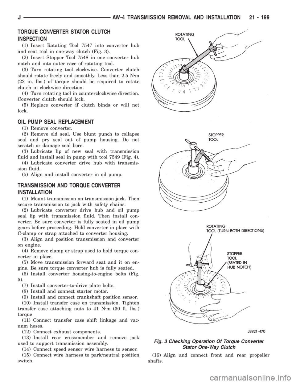
(1) Insert Rotating Tool 7547 into converter hub
and seat tool in one-way clutch (Fig. 3).
(2) Insert Stopper Tool 7548 in one converter hub
notch and into outer race of rotating tool.
(3) Turn rotating tool clockwise. Converter clutch
should rotate freely and smoothly. Less than 2.5 Nzm
(22 in. lbs.) of torque should be required to rotate
clutch in clockwise direction.
(4) Turn rotating tool in counterclockwise direction.
Converter clutch should lock.
(5) Replace converter if clutch binds or will not
lock.
OIL PUMP SEAL REPLACEMENT
(1) Remove converter.
(2) Remove old seal. Use blunt punch to collapse
seal and pry seal out of pump housing. Do not
scratch or damage seal bore.
(3) Lubricate lip of new seal with transmission
fluid and install seal in pump with tool 7549 (Fig. 4).
(4) Lubricate converter drive hub with transmis-
sion fluid.
(5) Align and install converter in oil pump.
TRANSMISSION AND TORQUE CONVERTER
INSTALLATION
(1) Mount transmission on transmission jack. Then
secure transmission to jack with safety chains.
(2) Lubricate converter drive hub and oil pump
seal lip with transmission fluid. Then install con-
verter. Be sure converter is fully seated in oil pump
gears before proceeding. Hold converter in place with
C-clamp or strap attached to converter housing.
(3) Align and position transmission and converter
on engine.
(4) Remove clamp or strap used to hold torque con-
verter in place.
(5) Move transmission forward seat and it on en-
gine. Be sure torque converter hub is fully seated.
(6) Install converter housing-to-engine bolts (Fig.
5).
(7) Install converter-to-drive plate bolts.
(8) Install and connect starter motor.
(9) Install and connect crankshaft position sensor.
(10) Install transfer case on transmission. Tighten
transfer case attaching nuts to 41 Nzm (30 ft. lbs.)
torque
(11) Connect transfer case shift linkage and vac-
uum hoses.
(12) Connect exhaust components.
(13) Install rear crossmember and remove jack
used to support transmission assembly.
(14) Connect speed sensor wire harness to sensor.
(15) Connect wire harness to park/neutral position
switch.(16) Align and connect front and rear propeller
shafts.
Fig. 3 Checking Operation Of Torque Converter
Stator One-Way Clutch
JAW-4 TRANSMISSION REMOVAL AND INSTALLATION 21 - 199
Page 1604 of 2198
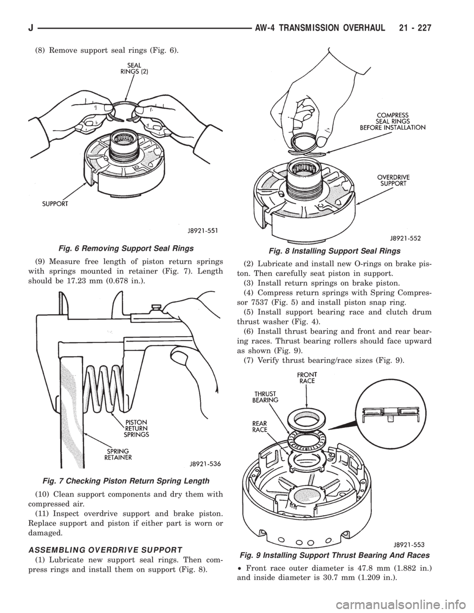
(8) Remove support seal rings (Fig. 6).
(9) Measure free length of piston return springs
with springs mounted in retainer (Fig. 7). Length
should be 17.23 mm (0.678 in.).
(10) Clean support components and dry them with
compressed air.
(11) Inspect overdrive support and brake piston.
Replace support and piston if either part is worn or
damaged.
ASSEMBLING OVERDRIVE SUPPORT
(1) Lubricate new support seal rings. Then com-
press rings and install them on support (Fig. 8).(2) Lubricate and install new O-rings on brake pis-
ton. Then carefully seat piston in support.
(3) Install return springs on brake piston.
(4) Compress return springs with Spring Compres-
sor 7537 (Fig. 5) and install piston snap ring.
(5) Install support bearing race and clutch drum
thrust washer (Fig. 4).
(6) Install thrust bearing and front and rear bear-
ing races. Thrust bearing rollers should face upward
as shown (Fig. 9).
(7) Verify thrust bearing/race sizes (Fig. 9).
²Front race outer diameter is 47.8 mm (1.882 in.)
and inside diameter is 30.7 mm (1.209 in.).
Fig. 6 Removing Support Seal Rings
Fig. 7 Checking Piston Return Spring Length
Fig. 8 Installing Support Seal Rings
Fig. 9 Installing Support Thrust Bearing And Races
JAW-4 TRANSMISSION OVERHAUL 21 - 227
Page 1606 of 2198
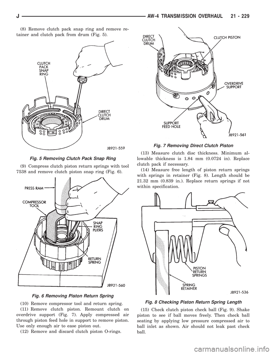
(8) Remove clutch pack snap ring and remove re-
tainer and clutch pack from drum (Fig. 5).
(9) Compress clutch piston return springs with tool
7538 and remove clutch piston snap ring (Fig. 6).
(10) Remove compressor tool and return spring.
(11) Remove clutch piston. Remount clutch on
overdrive support (Fig. 7). Apply compressed air
through piston feed hole in support to remove piston.
Use only enough air to ease piston out.
(12) Remove and discard clutch piston O-rings.(13) Measure clutch disc thickness. Minimum al-
lowable thickness is 1.84 mm (0.0724 in). Replace
clutch pack if necessary.
(14) Measure free length of piston return springs
with springs in retainer (Fig. 8). Length should be
21.32 mm (0.839 in.). Replace return springs if not
within specification.
(15) Check clutch piston check ball (Fig. 9). Shake
piston to see if ball moves freely. Then check ball
seating by applying low pressure compressed air to
ball inlet as shown. Air should not leak past check
ball.
Fig. 5 Removing Clutch Pack Snap Ring
Fig. 6 Removing Piston Return Spring
Fig. 7 Removing Direct Clutch Piston
Fig. 8 Checking Piston Return Spring Length
JAW-4 TRANSMISSION OVERHAUL 21 - 229
Page 1607 of 2198
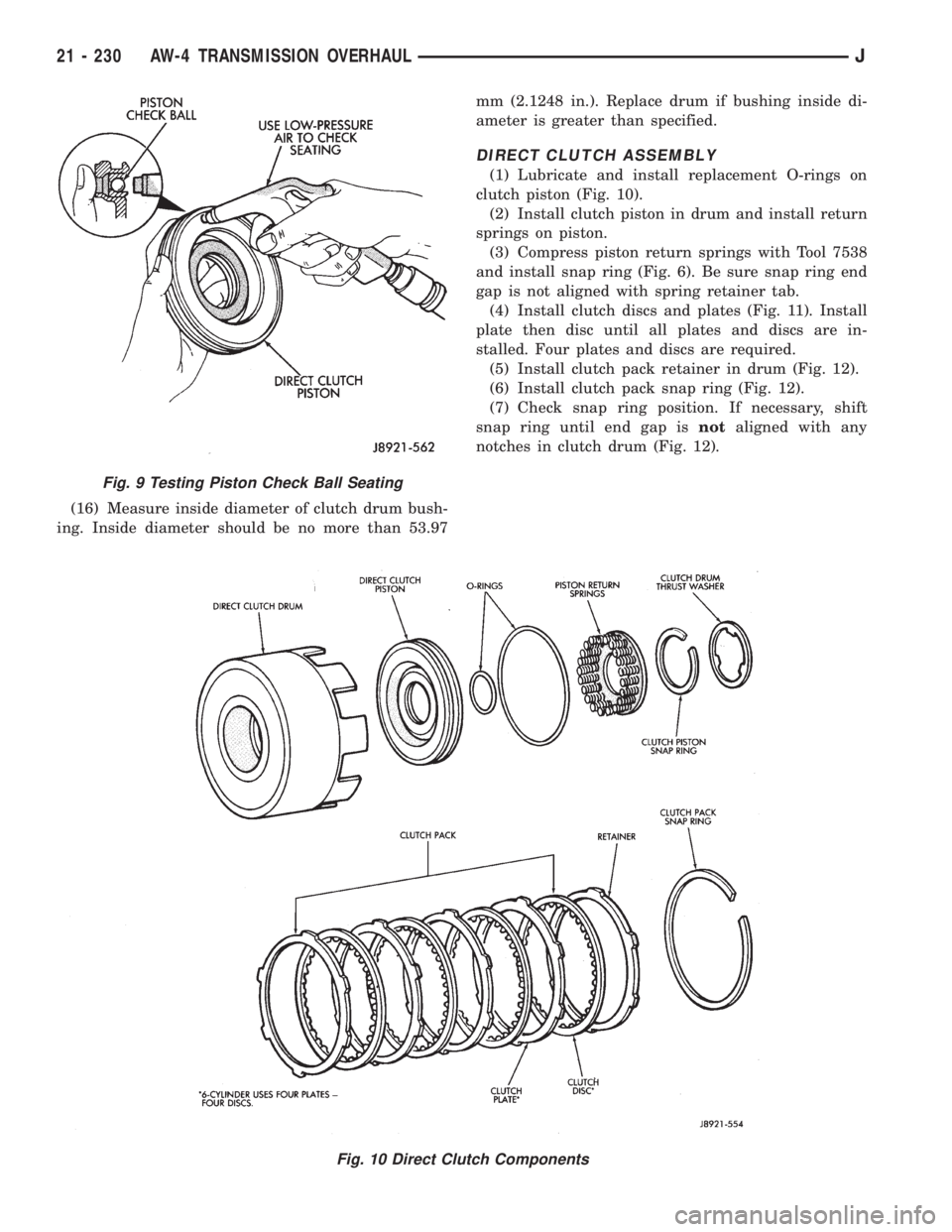
(16) Measure inside diameter of clutch drum bush-
ing. Inside diameter should be no more than 53.97mm (2.1248 in.). Replace drum if bushing inside di-
ameter is greater than specified.
DIRECT CLUTCH ASSEMBLY
(1) Lubricate and install replacement O-rings on
clutch piston (Fig. 10).
(2) Install clutch piston in drum and install return
springs on piston.
(3) Compress piston return springs with Tool 7538
and install snap ring (Fig. 6). Be sure snap ring end
gap is not aligned with spring retainer tab.
(4) Install clutch discs and plates (Fig. 11). Install
plate then disc until all plates and discs are in-
stalled. Four plates and discs are required.
(5) Install clutch pack retainer in drum (Fig. 12).
(6) Install clutch pack snap ring (Fig. 12).
(7) Check snap ring position. If necessary, shift
snap ring until end gap isnotaligned with any
notches in clutch drum (Fig. 12).
Fig. 10 Direct Clutch Components
Fig. 9 Testing Piston Check Ball Seating
21 - 230 AW-4 TRANSMISSION OVERHAULJ
Page 1608 of 2198
(8) Lubricate clutch drum thrust washer with pe-
troleum jelly and install it in drum (Fig. 3).
(9) Mount direct clutch assembly on forward clutch
assembly and check assembled height (Fig. 14).
Height should be 70.3 to 71.5 mm (2.767 to 2.815
in.).
(10) If assembled height is incorrect, clutches are
not seated.
(11) If clutch height is OK, remove direct clutch
from forward clutch and proceed to forward clutch
overhaul.
Fig. 11 Installing Direct Clutch Discs And Plates
Fig. 12 Install Clutch Pack Retainer
Fig. 13 Adjusting Clutch Pack Snap Ring Position
Fig. 14 Checking Direct Clutch Assembled Height
JAW-4 TRANSMISSION OVERHAUL 21 - 231
Page 1612 of 2198
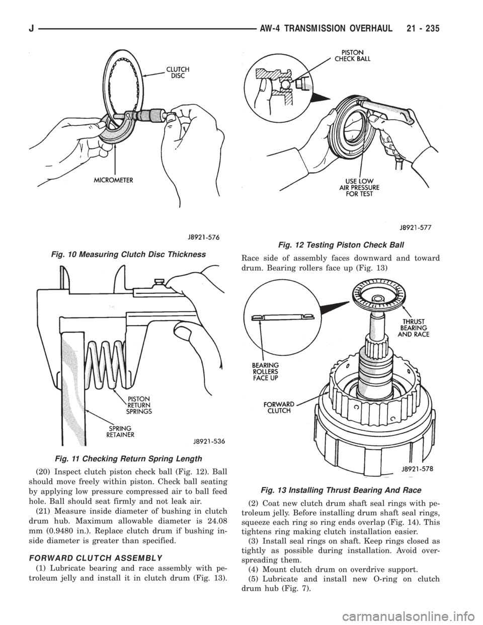
(20) Inspect clutch piston check ball (Fig. 12). Ball
should move freely within piston. Check ball seating
by applying low pressure compressed air to ball feed
hole. Ball should seat firmly and not leak air.
(21) Measure inside diameter of bushing in clutch
drum hub. Maximum allowable diameter is 24.08
mm (0.9480 in.). Replace clutch drum if bushing in-
side diameter is greater than specified.
FORWARD CLUTCH ASSEMBLY
(1) Lubricate bearing and race assembly with pe-
troleum jelly and install it in clutch drum (Fig. 13).Race side of assembly faces downward and toward
drum. Bearing rollers face up (Fig. 13)
(2) Coat new clutch drum shaft seal rings with pe-
troleum jelly. Before installing drum shaft seal rings,
squeeze each ring so ring ends overlap (Fig. 14). This
tightens ring making clutch installation easier.
(3) Install seal rings on shaft. Keep rings closed as
tightly as possible during installation. Avoid over-
spreading them.
(4) Mount clutch drum on overdrive support.
(5) Lubricate and install new O-ring on clutch
drum hub (Fig. 7).
Fig. 10 Measuring Clutch Disc Thickness
Fig. 11 Checking Return Spring Length
Fig. 12 Testing Piston Check Ball
Fig. 13 Installing Thrust Bearing And Race
JAW-4 TRANSMISSION OVERHAUL 21 - 235
Page 1613 of 2198
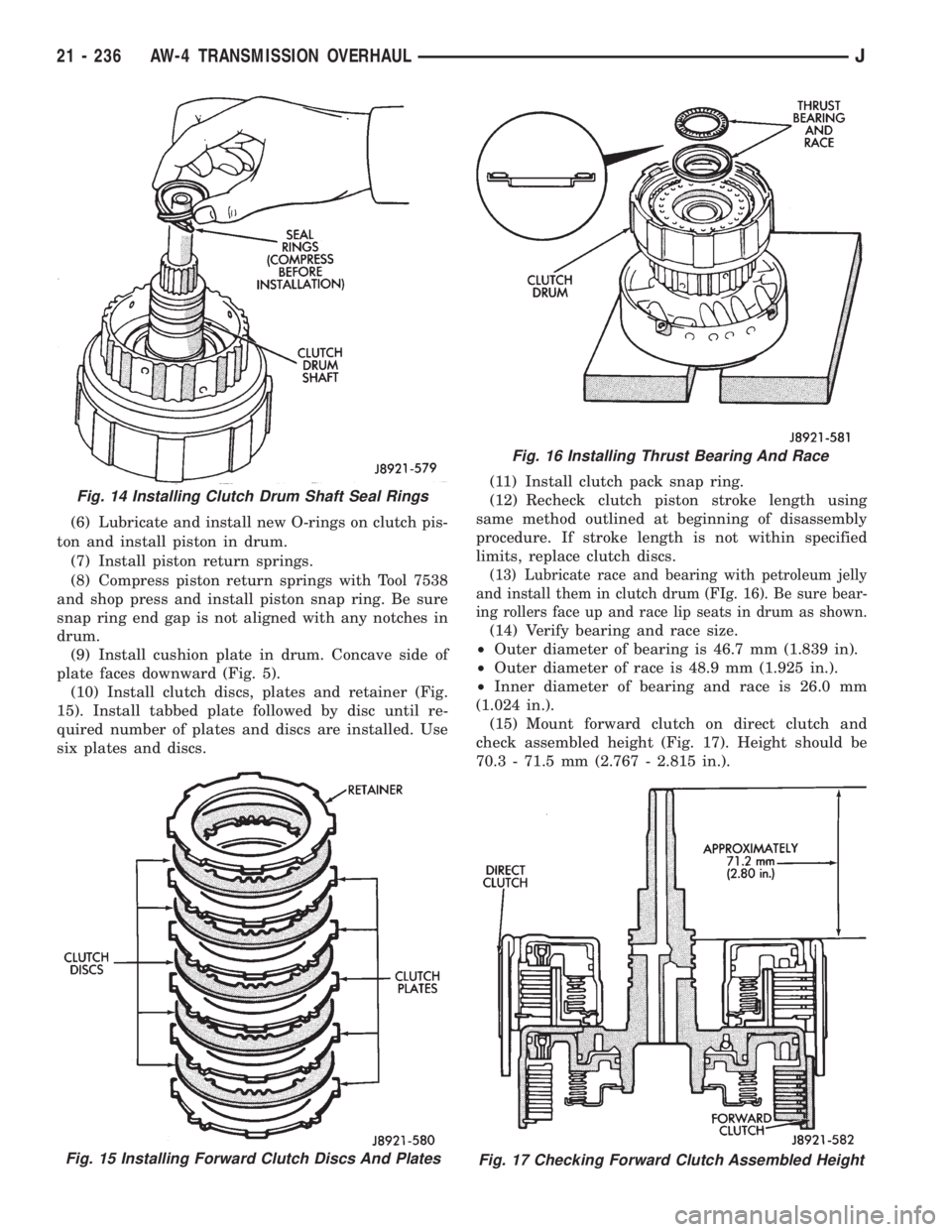
(6) Lubricate and install new O-rings on clutch pis-
ton and install piston in drum.
(7) Install piston return springs.
(8) Compress piston return springs with Tool 7538
and shop press and install piston snap ring. Be sure
snap ring end gap is not aligned with any notches in
drum.
(9) Install cushion plate in drum. Concave side of
plate faces downward (Fig. 5).
(10) Install clutch discs, plates and retainer (Fig.
15). Install tabbed plate followed by disc until re-
quired number of plates and discs are installed. Use
six plates and discs.(11) Install clutch pack snap ring.
(12) Recheck clutch piston stroke length using
same method outlined at beginning of disassembly
procedure. If stroke length is not within specified
limits, replace clutch discs.
(13) Lubricate race and bearing with petroleum jelly
and install them in clutch drum (FIg. 16). Be sure bear-
ing rollers face up and race lip seats in drum as shown.
(14) Verify bearing and race size.
²Outer diameter of bearing is 46.7 mm (1.839 in).
²Outer diameter of race is 48.9 mm (1.925 in.).
²Inner diameter of bearing and race is 26.0 mm
(1.024 in.).
(15) Mount forward clutch on direct clutch and
check assembled height (Fig. 17). Height should be
70.3 - 71.5 mm (2.767 - 2.815 in.).
Fig. 15 Installing Forward Clutch Discs And Plates
Fig. 16 Installing Thrust Bearing And Race
Fig. 17 Checking Forward Clutch Assembled Height
Fig. 14 Installing Clutch Drum Shaft Seal Rings
21 - 236 AW-4 TRANSMISSION OVERHAULJ