1995 JEEP CHEROKEE seat
[x] Cancel search: seatPage 1522 of 2198
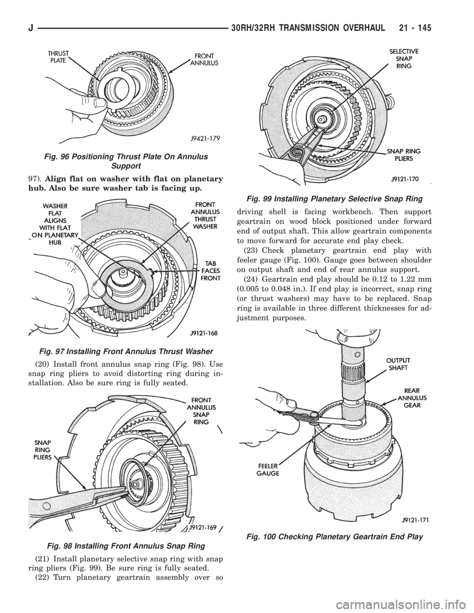
97).Align flat on washer with flat on planetary
hub. Also be sure washer tab is facing up.
(20) Install front annulus snap ring (Fig. 98). Use
snap ring pliers to avoid distorting ring during in-
stallation. Also be sure ring is fully seated.
(21) Install planetary selective snap ring with snap
ring pliers (Fig. 99). Be sure ring is fully seated.
(22) Turn planetary geartrain assembly over sodriving shell is facing workbench. Then support
geartrain on wood block positioned under forward
end of output shaft. This allow geartrain components
to move forward for accurate end play check.
(23) Check planetary geartrain end play with
feeler gauge (Fig. 100). Gauge goes between shoulder
on output shaft and end of rear annulus support.
(24) Geartrain end play should be 0.12 to 1.22 mm
(0.005 to 0.048 in.). If end play is incorrect, snap ring
(or thrust washers) may have to be replaced. Snap
ring is available in three different thicknesses for ad-
justment purposes.
Fig. 96 Positioning Thrust Plate On Annulus
Support
Fig. 97 Installing Front Annulus Thrust Washer
Fig. 98 Installing Front Annulus Snap Ring
Fig. 99 Installing Planetary Selective Snap Ring
Fig. 100 Checking Planetary Geartrain End Play
J30RH/32RH TRANSMISSION OVERHAUL 21 - 145
Page 1530 of 2198
VALVE BODY ASSEMBLY AND ADJUSTMENT
CAUTION: Do not force valves or plugs into place
during reassembly. If the valve body bores, valves
and plugs are free of distortion or burrs, the valve
body components should all slide into place easily.
In addition, do not overtighten the transfer plate
and valve body screws during reassembly. Over-
tightening can distort the valve body resulting in
valve sticking, cross leakage and unsatisfactory op-
eration. Tighten valve body screws to recom-
mended torque only.
(1) Lubricate valve body bores, valves and plugs
with Mopar ATF Plus transmission fluid.
(2) Insert rear clutch and rear servo check balls in
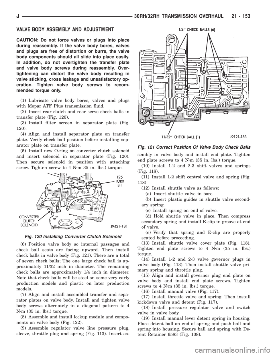
transfer plate (Fig. 120).
(3) Install filter screen in separator plate (Fig.
120).
(4) Align and install separator plate on transfer
plate. Verify check ball position before installing sep-
arator plate on transfer plate.
(5) Install new O-ring on converter clutch solenoid
and insert solenoid in separator plate (Fig. 120).
Then secure solenoid in position with attaching
screw. Tighten screw to 4 Nzm 35 in. lbs.) torque.
(6) Position valve body so internal passages and
check ball seats are facing upward. Then install
check balls in valve body (Fig. 121). There are a total
of seven check balls; The one large check ball is ap-
proximately 11/32 inch in diameter. The remaining
check balls are approximately 1/4 inch in diameter.
Note that check balls will be steel on some very early
production models and plastic on later production
models.
(7) Align and install assembled transfer and sepa-
rator plates on valve body. Install and tighten valve
body screws alternately in a diagonal pattern to 4
Nzm (35 in. lbs.) torque.
(8) Assemble and install lockup module and compo-
nents on valve body (Fig. 122).
(9) Assemble regulator valve line pressure plug,
sleeve, throttle plug and spring (Fig. 113). Insert as-sembly in valve body and install end plate. Tighten
end plate screws to 4 Nzm (35 in. lbs.) torque.
(10) Install 1-2 and 2-3 shift valves and springs
(Fig. 118).
(11) Install 1-2 shift control valve and spring (Fig.
118)
(12) Install shuttle valve as follows:
(a) Insert shuttle valve in bore.
(b) Insert plastic guides in shuttle valve second-
ary spring.
(c) Install spring on end of valve.
(d) Hold shuttle valve in place. Then compress
secondary spring and install E-clip in groove at end
of valve.
(e) Verify that spring and E-clip are properly
seated before proceeding.
(13) Install shuttle valve cover plate (Fig. 118).
Tighten end plate screws to 4 Nzm (35 in. lbs.)
torque.
(14) Install 1-2 and 2-3 valve governor plugs in
valve body (Fig. 113). Then install shuttle valve pri-
mary spring and throttle plug.
(15) Align and install governor plug end plate on
valve body and install end plate screws. Tighten
screws to 4 Nzm (35 in. lbs.) torque.
(16) Install manual valve (Fig. 117).
(17) Install throttle valve and spring. Then install
kickdown valve and detent (Fig. 117).
(18) Install pressure regulator valve and switch
valve in valve body.
(19) Install manual lever detent spring in housing.
Place detent ball on end of spring and push ball and
spring into housing. Secure ball and spring with De-
tent Retainer 6583 (Fig. 108).
Fig. 120 Installing Converter Clutch Solenoid
Fig. 121 Correct Position Of Valve Body Check Balls
J30RH/32RH TRANSMISSION OVERHAUL 21 - 153
Page 1531 of 2198
(20) Insert line pressure adjusting screw in adjust-
ing screw bracket (Fig. 107).
(21) Install spring on end of line pressure regula-
tor valve.
(22) Install switch valve spring on tang at end of
adjusting screw bracket (Fig. 107).
(23) Position adjusting screw bracket on valve
body. Align valve springs and press bracket into
place. Install short, upper bracket screws first and
long bottom screw last. Verify that valve springs and
bracket are properly aligned. Then tighten all three
bracket screws to 4 Nzm (35 in. lbs.) torque.
(24) Install module and connecting tube. Be sure
long end of tube goes to module (Fig. 111). Tighten
module screws to 4 Nzm (35 in. lbs.) torque.
(25) Install throttle lever in valve body. Then in-
stall manual lever over throttle lever and start man-
ual lever into valve body.
(26) Align manual lever detent with detent ball
and align lever arm with manual valve. Hold throttle
lever upward. Then press down on manual lever un-
til lever is fully seated.
(27) Install manual lever seal, washer and retain-
ing E-clip.
(28) Lubricate shaft of manual lever with light
coat of petroleum jelly. This will help protect seal lip
when manual shaft seal is installed.
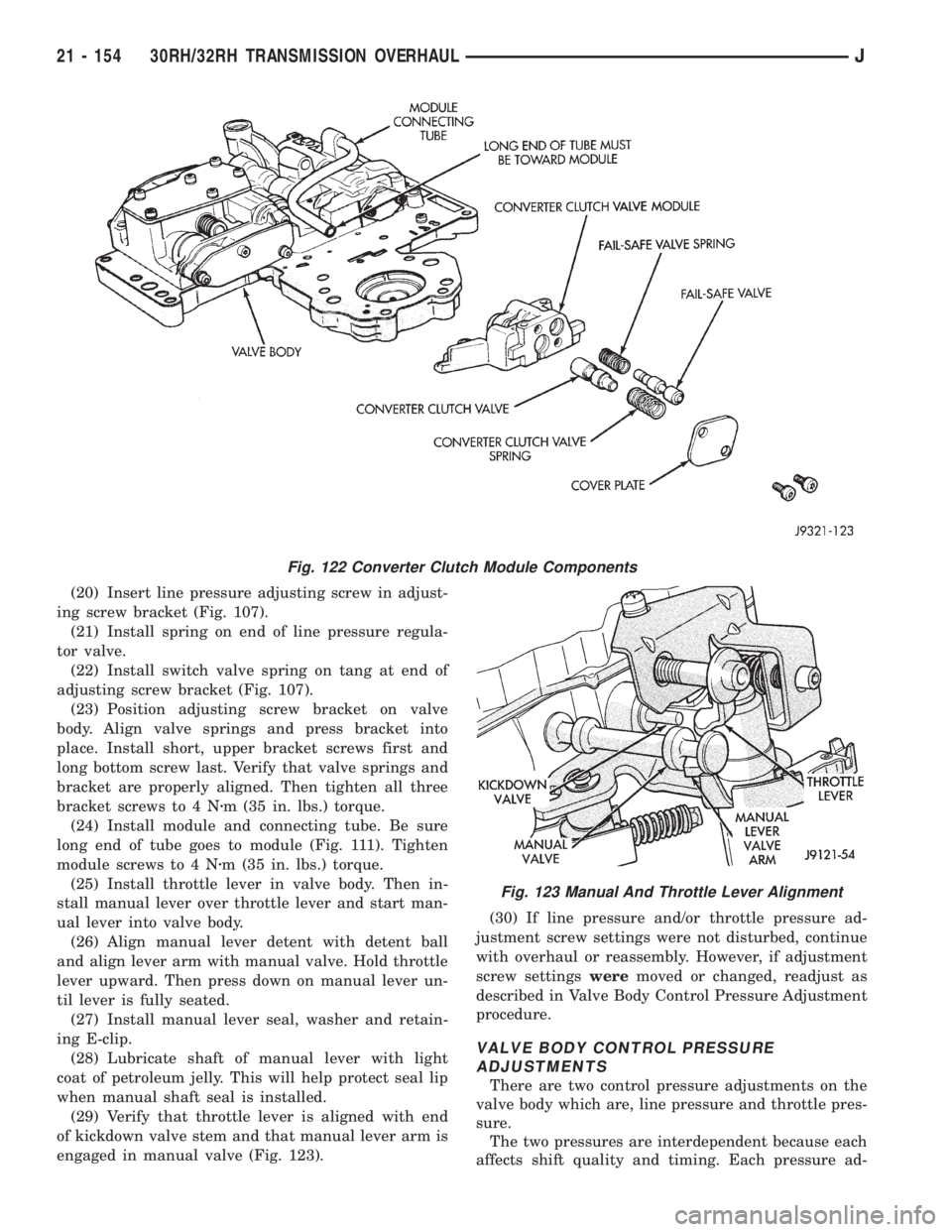
(29) Verify that throttle lever is aligned with end
of kickdown valve stem and that manual lever arm is
engaged in manual valve (Fig. 123).(30) If line pressure and/or throttle pressure ad-
justment screw settings were not disturbed, continue
with overhaul or reassembly. However, if adjustment
screw settingsweremoved or changed, readjust as
described in Valve Body Control Pressure Adjustment
procedure.
VALVE BODY CONTROL PRESSURE
ADJUSTMENTS
There are two control pressure adjustments on the
valve body which are, line pressure and throttle pres-
sure.
The two pressures are interdependent because each
affects shift quality and timing. Each pressure ad-
Fig. 122 Converter Clutch Module Components
Fig. 123 Manual And Throttle Lever Alignment
21 - 154 30RH/32RH TRANSMISSION OVERHAULJ
Page 1533 of 2198
OVERRUNNING CLUTCH INSTALLATION
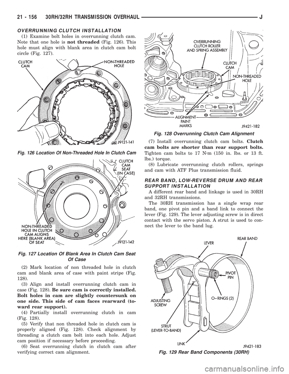
(1) Examine bolt holes in overrunning clutch cam.
Note that one hole isnot threaded(Fig. 126). This
hole must align with blank area in clutch cam bolt
circle (Fig. 127).
(2) Mark location of non threaded hole in clutch
cam and blank area of case with paint stripe (Fig.
128).
(3) Align and install overrunning clutch cam in
case (Fig. 128).Be sure cam is correctly installed.
Bolt holes in cam are slightly countersunk on
one side. This side of cam faces rearward (to-
ward rear support).
(4) Partially install overrunning clutch in cam
(Fig. 128).
(5) Verify that non threaded hole in clutch cam is
properly aligned (Fig. 128). Check alignment by
threading a clutch cam bolt into each hole. Adjust
cam position if necessary before proceeding.
(6) Seat overrunning clutch in clutch cam after
verifying correct cam alignment.(7) Install overrunning clutch cam bolts.Clutch
cam bolts are shorter than rear support bolts.
Tighten cam bolts to 17 Nzm (150 in. lbs. or 13 ft.
lbs.) torque.
(8) Lubricate overrunning clutch rollers, springs
and cam with ATF Plus transmission fluid.
REAR BAND, LOW-REVERSE DRUM AND REAR
SUPPORT INSTALLATION
A different rear band and linkage is used in 30RH
and 32RH transmissions.
The 30RH transmission has a single wrap rear
band, one pivot pin and a band link to connect the
lever (Fig. 129). The lever adjusting screw is in direct
contact with the servo piston. A strut is used to con-
nect the lever to the band lug.
Fig. 126 Location Of Non-Threaded Hole In Clutch Cam
Fig. 127 Location Of Blank Area In Clutch Cam Seat
Of Case
Fig. 128 Overrunning Clutch Cam Alignment
Fig. 129 Rear Band Components (30RH)
21 - 156 30RH/32RH TRANSMISSION OVERHAULJ
Page 1534 of 2198
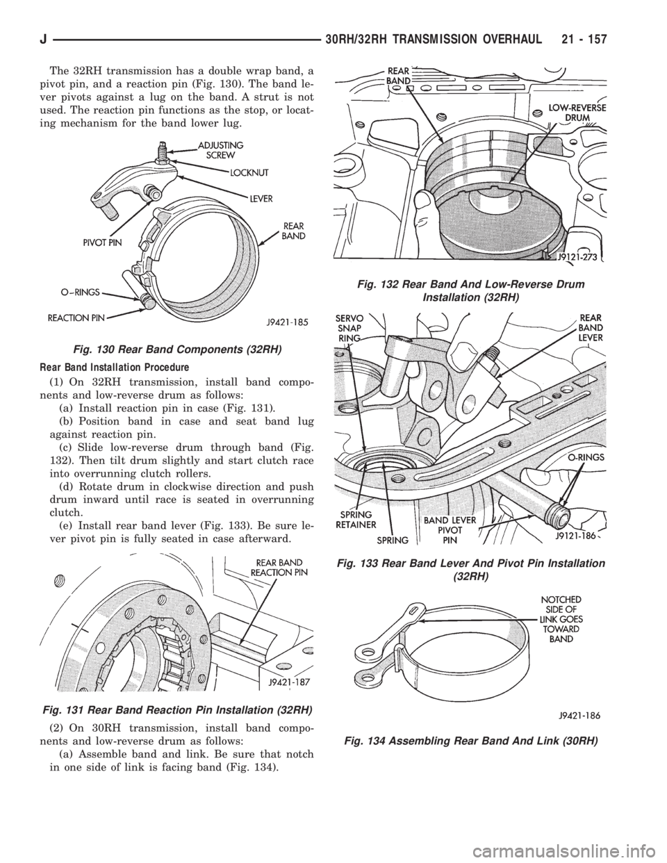
The 32RH transmission has a double wrap band, a
pivot pin, and a reaction pin (Fig. 130). The band le-
ver pivots against a lug on the band. A strut is not
used. The reaction pin functions as the stop, or locat-
ing mechanism for the band lower lug.
Rear Band Installation Procedure
(1) On 32RH transmission, install band compo-
nents and low-reverse drum as follows:
(a) Install reaction pin in case (Fig. 131).
(b) Position band in case and seat band lug
against reaction pin.
(c) Slide low-reverse drum through band (Fig.
132). Then tilt drum slightly and start clutch race
into overrunning clutch rollers.
(d) Rotate drum in clockwise direction and push
drum inward until race is seated in overrunning
clutch.
(e) Install rear band lever (Fig. 133). Be sure le-
ver pivot pin is fully seated in case afterward.
(2) On 30RH transmission, install band compo-
nents and low-reverse drum as follows:
(a) Assemble band and link. Be sure that notch
in one side of link is facing band (Fig. 134).
Fig. 130 Rear Band Components (32RH)
Fig. 131 Rear Band Reaction Pin Installation (32RH)
Fig. 132 Rear Band And Low-Reverse Drum
Installation (32RH)
Fig. 133 Rear Band Lever And Pivot Pin Installation
(32RH)
Fig. 134 Assembling Rear Band And Link (30RH)
J30RH/32RH TRANSMISSION OVERHAUL 21 - 157
Page 1535 of 2198
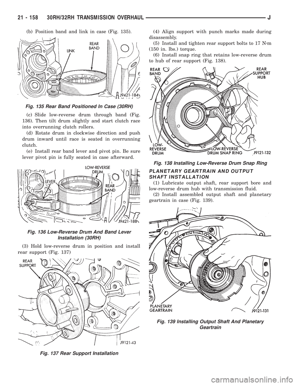
(b) Position band and link in case (Fig. 135).
(c) Slide low-reverse drum through band (Fig.
136). Then tilt drum slightly and start clutch race
into overrunning clutch rollers.
(d) Rotate drum in clockwise direction and push
drum inward until race is seated in overrunning
clutch.
(e) Install rear band lever and pivot pin. Be sure
lever pivot pin is fully seated in case afterward.
(3) Hold low-reverse drum in position and install
rear support (Fig. 137)(4) Align support with punch marks made during
disassembly.
(5) Install and tighten rear support bolts to 17 Nzm
(150 in. lbs.) torque.
(6) Install snap ring that retains low-reverse drum
to hub of rear support (Fig. 138).
PLANETARY GEARTRAIN AND OUTPUT
SHAFT INSTALLATION
(1) Lubricate output shaft, rear support bore and
low-reverse drum hub with transmission fluid.
(2) Install assembled output shaft and planetary
geartrain in case (Fig. 139).
Fig. 135 Rear Band Positioned In Case (30RH)
Fig. 136 Low-Reverse Drum And Band Lever
Installation (30RH)
Fig. 137 Rear Support Installation
Fig. 138 Installing Low-Reverse Drum Snap Ring
Fig. 139 Installing Output Shaft And Planetary
Geartrain
21 - 158 30RH/32RH TRANSMISSION OVERHAULJ
Page 1536 of 2198
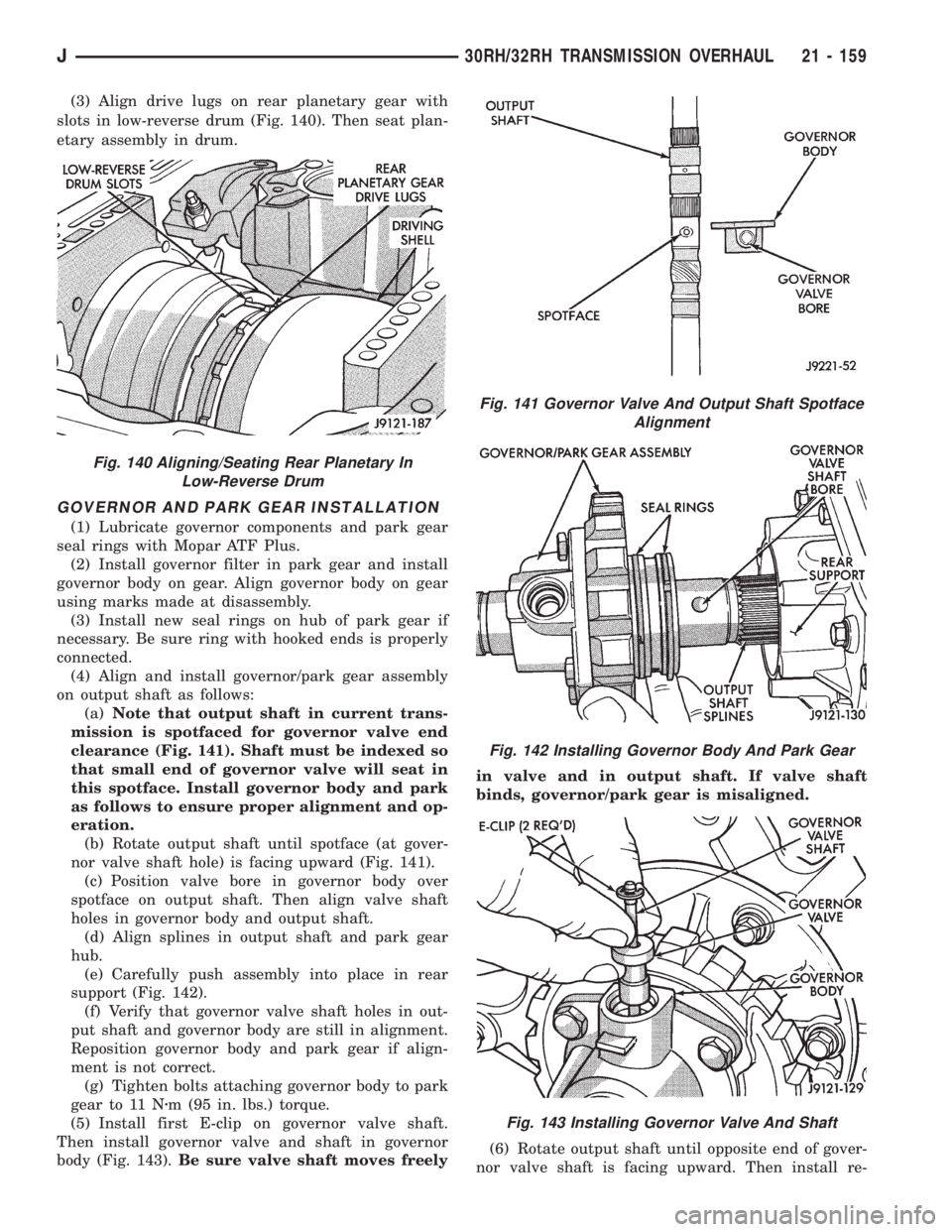
(3) Align drive lugs on rear planetary gear with
slots in low-reverse drum (Fig. 140). Then seat plan-
etary assembly in drum.
GOVERNOR AND PARK GEAR INSTALLATION
(1) Lubricate governor components and park gear
seal rings with Mopar ATF Plus.
(2) Install governor filter in park gear and install
governor body on gear. Align governor body on gear
using marks made at disassembly.
(3) Install new seal rings on hub of park gear if
necessary. Be sure ring with hooked ends is properly
connected.
(4) Align and install governor/park gear assembly
on output shaft as follows:
(a)Note that output shaft in current trans-
mission is spotfaced for governor valve end
clearance (Fig. 141). Shaft must be indexed so
that small end of governor valve will seat in
this spotface. Install governor body and park
as follows to ensure proper alignment and op-
eration.
(b) Rotate output shaft until spotface (at gover-
nor valve shaft hole) is facing upward (Fig. 141).
(c) Position valve bore in governor body over
spotface on output shaft. Then align valve shaft
holes in governor body and output shaft.
(d) Align splines in output shaft and park gear
hub.
(e) Carefully push assembly into place in rear
support (Fig. 142).
(f) Verify that governor valve shaft holes in out-
put shaft and governor body are still in alignment.
Reposition governor body and park gear if align-
ment is not correct.
(g) Tighten bolts attaching governor body to park
gear to 11 Nzm (95 in. lbs.) torque.
(5) Install first E-clip on governor valve shaft.
Then install governor valve and shaft in governor
body (Fig. 143).Be sure valve shaft moves freelyin valve and in output shaft. If valve shaft
binds, governor/park gear is misaligned.
(6) Rotate output shaft until opposite end of gover-
nor valve shaft is facing upward. Then install re-
Fig. 140 Aligning/Seating Rear Planetary In
Low-Reverse Drum
Fig. 141 Governor Valve And Output Shaft Spotface
Alignment
Fig. 142 Installing Governor Body And Park Gear
Fig. 143 Installing Governor Valve And Shaft
J30RH/32RH TRANSMISSION OVERHAUL 21 - 159
Page 1537 of 2198
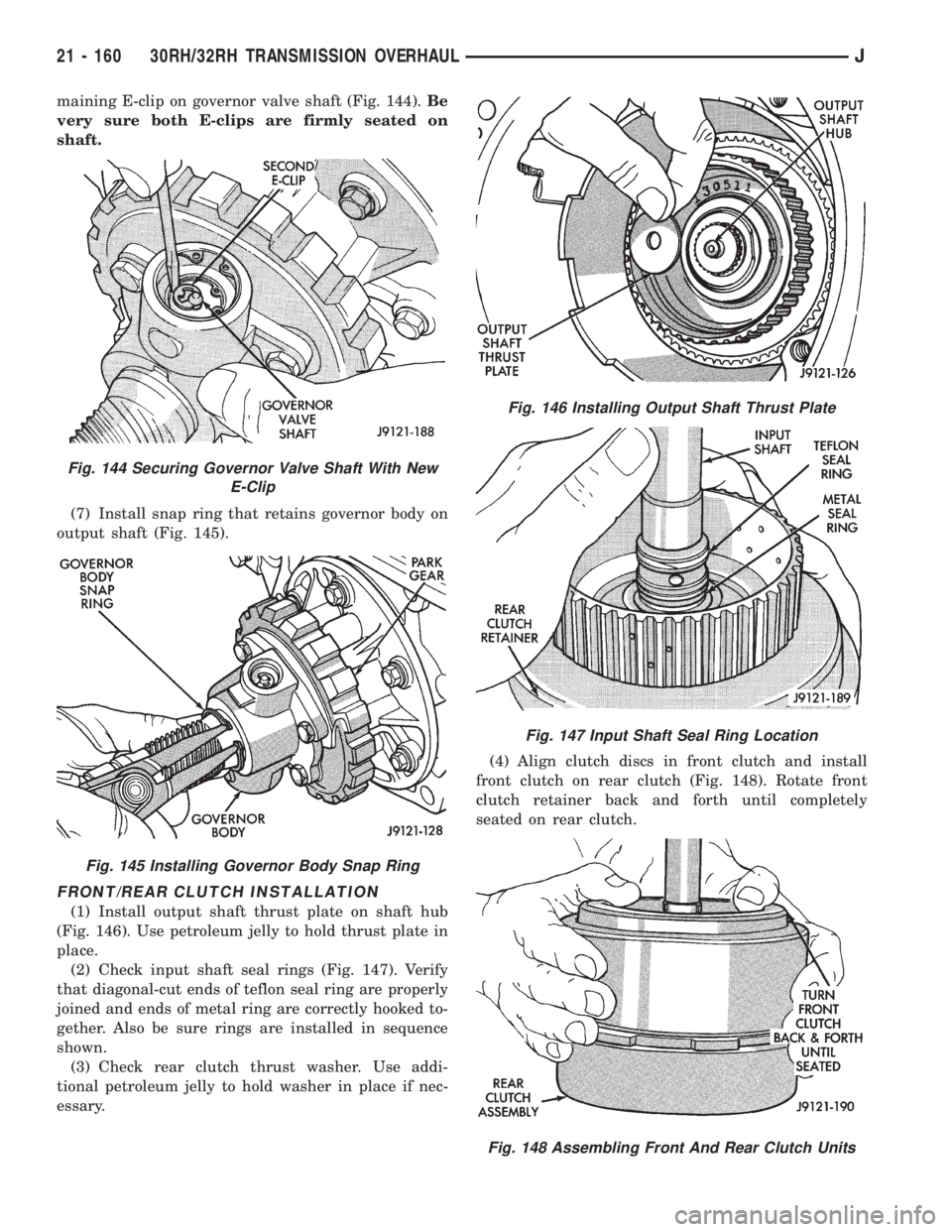
maining E-clip on governor valve shaft (Fig. 144).Be
very sure both E-clips are firmly seated on
shaft.
(7) Install snap ring that retains governor body on
output shaft (Fig. 145).
FRONT/REAR CLUTCH INSTALLATION
(1) Install output shaft thrust plate on shaft hub
(Fig. 146). Use petroleum jelly to hold thrust plate in
place.
(2) Check input shaft seal rings (Fig. 147). Verify
that diagonal-cut ends of teflon seal ring are properly
joined and ends of metal ring are correctly hooked to-
gether. Also be sure rings are installed in sequence
shown.
(3) Check rear clutch thrust washer. Use addi-
tional petroleum jelly to hold washer in place if nec-
essary.(4) Align clutch discs in front clutch and install
front clutch on rear clutch (Fig. 148). Rotate front
clutch retainer back and forth until completely
seated on rear clutch.
Fig. 144 Securing Governor Valve Shaft With New
E-Clip
Fig. 145 Installing Governor Body Snap Ring
Fig. 146 Installing Output Shaft Thrust Plate
Fig. 147 Input Shaft Seal Ring Location
Fig. 148 Assembling Front And Rear Clutch Units
21 - 160 30RH/32RH TRANSMISSION OVERHAULJ