Page 1678 of 2198
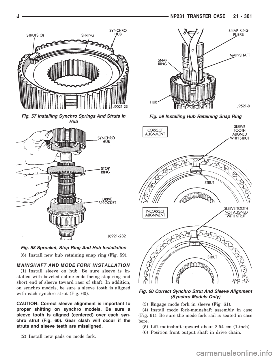
(6) Install new hub retaining snap ring (Fig. 59).
MAINSHAFT AND MODE FORK INSTALLATION
(1) Install sleeve on hub. Be sure sleeve is in-
stalled with beveled spline ends facing stop ring and
short end of sleeve toward raer of shaft. In addition,
on synchro models, be sure a sleeve tooth is aligned
with each synchro strut (Fig. 60).
CAUTION: Correct sleeve alignment is important to
proper shifting on synchro models. Be sure a
sleeve tooth is aligned (centered) over each syn-
chro strut (Fig. 60). Gear clash will occur if the
struts and sleeve teeth are misaligned.
(2) Install new pads on mode fork.(3) Engage mode fork in sleeve (Fig. 61).
(4) Install mode fork-mainshaft assembly in case
(Fig. 61). Be sure the mode fork rail is seated in case
bore.
(5) Lift mainshaft upward about 2.54 cm (1-inch).
(6) Position front output shaft in drive chain.
Fig. 57 Installing Synchro Springs And Struts In
Hub
Fig. 58 Sprocket, Stop Ring And Hub Installation
Fig. 59 Installing Hub Retaining Snap Ring
Fig. 60 Correct Synchro Strut And Sleeve Alignment
(Synchro Models Only)
JNP231 TRANSFER CASE 21 - 301
Page 1679 of 2198
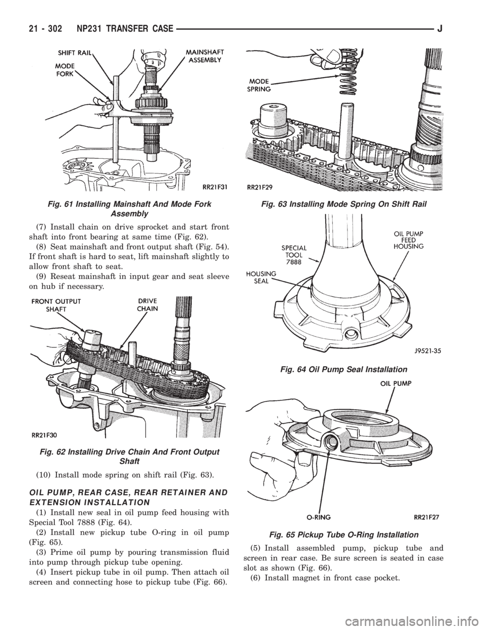
(7) Install chain on drive sprocket and start front
shaft into front bearing at same time (Fig. 62).
(8) Seat mainshaft and front output shaft (Fig. 54).
If front shaft is hard to seat, lift mainshaft slightly to
allow front shaft to seat.
(9) Reseat mainshaft in input gear and seat sleeve
on hub if necessary.
(10) Install mode spring on shift rail (Fig. 63).
OIL PUMP, REAR CASE, REAR RETAINER AND
EXTENSION INSTALLATION
(1) Install new seal in oil pump feed housing with
Special Tool 7888 (Fig. 64).
(2) Install new pickup tube O-ring in oil pump
(Fig. 65).
(3) Prime oil pump by pouring transmission fluid
into pump through pickup tube opening.
(4) Insert pickup tube in oil pump. Then attach oil
screen and connecting hose to pickup tube (Fig. 66).(5) Install assembled pump, pickup tube and
screen in rear case. Be sure screen is seated in case
slot as shown (Fig. 66).
(6) Install magnet in front case pocket.
Fig. 61 Installing Mainshaft And Mode Fork
Assembly
Fig. 62 Installing Drive Chain And Front Output
Shaft
Fig. 63 Installing Mode Spring On Shift Rail
Fig. 64 Oil Pump Seal Installation
Fig. 65 Pickup Tube O-Ring Installation
21 - 302 NP231 TRANSFER CASEJ
Page 1680 of 2198
(7) Clean sealing surfaces of rear case front case,
retainer and extension. Use 3M all puspose cleaner
or equivalent product.
(8) Apply 3 mm (1/8 in.) wide bead of Mopar gas-
ket maker, silicone adhesive sealer, or Loctite 518 to
sealing surface of front case.
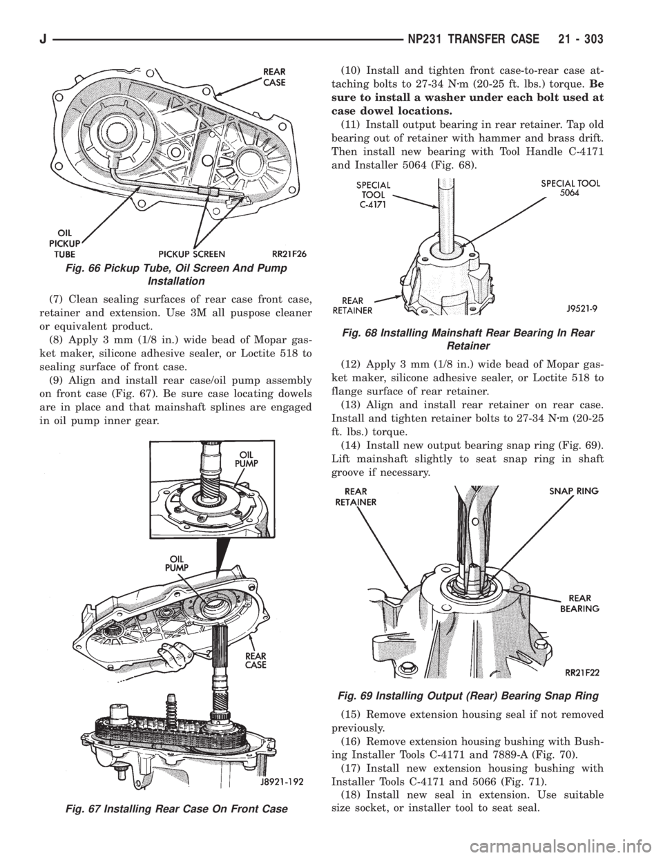
(9) Align and install rear case/oil pump assembly
on front case (Fig. 67). Be sure case locating dowels
are in place and that mainshaft splines are engaged
in oil pump inner gear.(10) Install and tighten front case-to-rear case at-
taching bolts to 27-34 Nzm (20-25 ft. lbs.) torque.Be
sure to install a washer under each bolt used at
case dowel locations.
(11) Install output bearing in rear retainer. Tap old
bearing out of retainer with hammer and brass drift.
Then install new bearing with Tool Handle C-4171
and Installer 5064 (Fig. 68).
(12) Apply 3 mm (1/8 in.) wide bead of Mopar gas-
ket maker, silicone adhesive sealer, or Loctite 518 to
flange surface of rear retainer.
(13) Align and install rear retainer on rear case.
Install and tighten retainer bolts to 27-34 Nzm (20-25
ft. lbs.) torque.
(14) Install new output bearing snap ring (Fig. 69).
Lift mainshaft slightly to seat snap ring in shaft
groove if necessary.
(15) Remove extension housing seal if not removed
previously.
(16) Remove extension housing bushing with Bush-
ing Installer Tools C-4171 and 7889-A (Fig. 70).
(17) Install new extension housing bushing with
Installer Tools C-4171 and 5066 (Fig. 71).
(18) Install new seal in extension. Use suitable
size socket, or installer tool to seat seal.
Fig. 67 Installing Rear Case On Front Case
Fig. 66 Pickup Tube, Oil Screen And Pump
Installation
Fig. 68 Installing Mainshaft Rear Bearing In Rear
Retainer
Fig. 69 Installing Output (Rear) Bearing Snap Ring
JNP231 TRANSFER CASE 21 - 303
Page 1684 of 2198
NP242 TRANSFER CASE
INDEX
page page
General Information....................... 307
Operating Ranges........................ 307
Overhaul Cleaning and Inspection............ 318
Recommended Lubricant/Capacity/Fill Level..... 307
Shift Lever Installation (XJ)................. 309
Shift Lever Removal (XJ)................... 309
Shift Linkage Adjustment................... 309
Shift Mechanism......................... 307Speedometer Service..................... 309
Transfer Case Assembly................... 319
Transfer Case Changes.................... 307
Transfer Case Disassembly and Overhaul...... 310
Transfer Case Identification................. 307
Transfer Case Installation.................. 309
Transfer Case Removal.................... 309
GENERAL INFORMATION
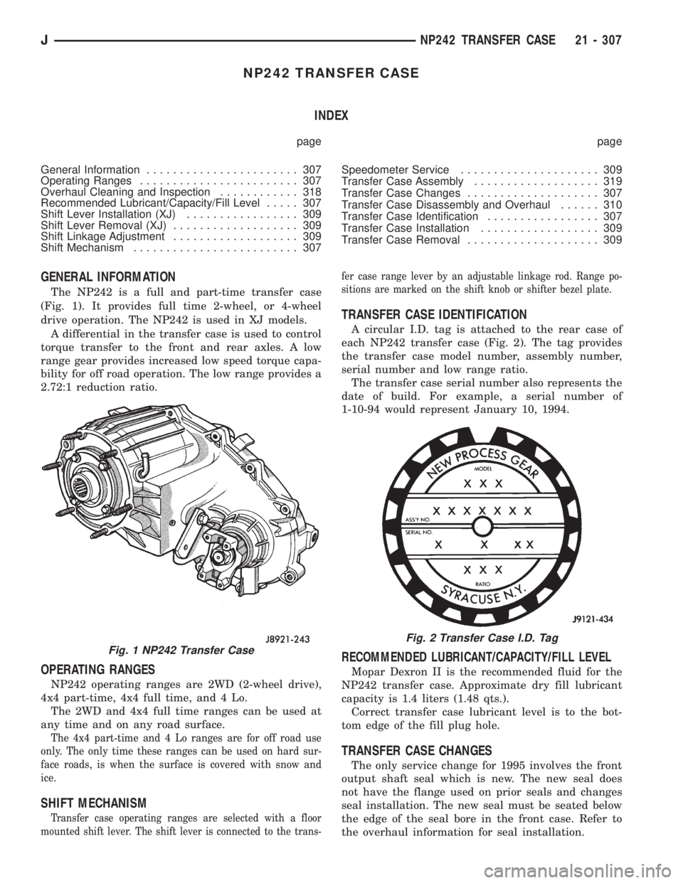
The NP242 is a full and part-time transfer case
(Fig. 1). It provides full time 2-wheel, or 4-wheel
drive operation. The NP242 is used in XJ models.
A differential in the transfer case is used to control
torque transfer to the front and rear axles. A low
range gear provides increased low speed torque capa-
bility for off road operation. The low range provides a
2.72:1 reduction ratio.
OPERATING RANGES
NP242 operating ranges are 2WD (2-wheel drive),
4x4 part-time, 4x4 full time, and 4 Lo.
The 2WD and 4x4 full time ranges can be used at
any time and on any road surface.
The 4x4 part-time and 4 Lo ranges are for off road use
only. The only time these ranges can be used on hard sur-
face roads, is when the surface is covered with snow and
ice.
SHIFT MECHANISM
Transfer case operating ranges are selected with a floor
mounted shift lever. The shift lever is connected to the trans-fer case range lever by an adjustable linkage rod. Range po-
sitions are marked on the shift knob or shifter bezel plate.
TRANSFER CASE IDENTIFICATION
A circular I.D. tag is attached to the rear case of
each NP242 transfer case (Fig. 2). The tag provides
the transfer case model number, assembly number,
serial number and low range ratio.
The transfer case serial number also represents the
date of build. For example, a serial number of
1-10-94 would represent January 10, 1994.
RECOMMENDED LUBRICANT/CAPACITY/FILL LEVEL
Mopar Dexron II is the recommended fluid for the
NP242 transfer case. Approximate dry fill lubricant
capacity is 1.4 liters (1.48 qts.).
Correct transfer case lubricant level is to the bot-
tom edge of the fill plug hole.
TRANSFER CASE CHANGES
The only service change for 1995 involves the front
output shaft seal which is new. The new seal does
not have the flange used on prior seals and changes
seal installation. The new seal must be seated below
the edge of the seal bore in the front case. Refer to
the overhaul information for seal installation.
Fig. 1 NP242 Transfer Case
Fig. 2 Transfer Case I.D. Tag
JNP242 TRANSFER CASE 21 - 307
Page 1689 of 2198
(13) Slide oil screen (Fig. 7) out of case pocket.
(14) Remove oil pump, pickup tube and oil screen
from rear case (Fig. 8).
(15) Remove pickup tube and screen from pump.
Do not disassemble oil pump; it is not repair-
able. Pumps are serviced only as an assembly.(16) Remove pickup tube O-ring from oil pump
(Fig. 9).
(17) Remove and discard oil pump seal.
(18) Remove magnet from front case.
(19) Remove drive sprocket snap ring (Fig. 10).
Fig. 7 Unseating Oil Screen
Fig. 8 Oil Pump/Pickup Tube/Screen Removal
Fig. 9 Pickup Tube O-Ring Removal
Fig. 10 Drive Sprocket Snap Ring Removal
21 - 312 NP242 TRANSFER CASEJ
Page 1696 of 2198
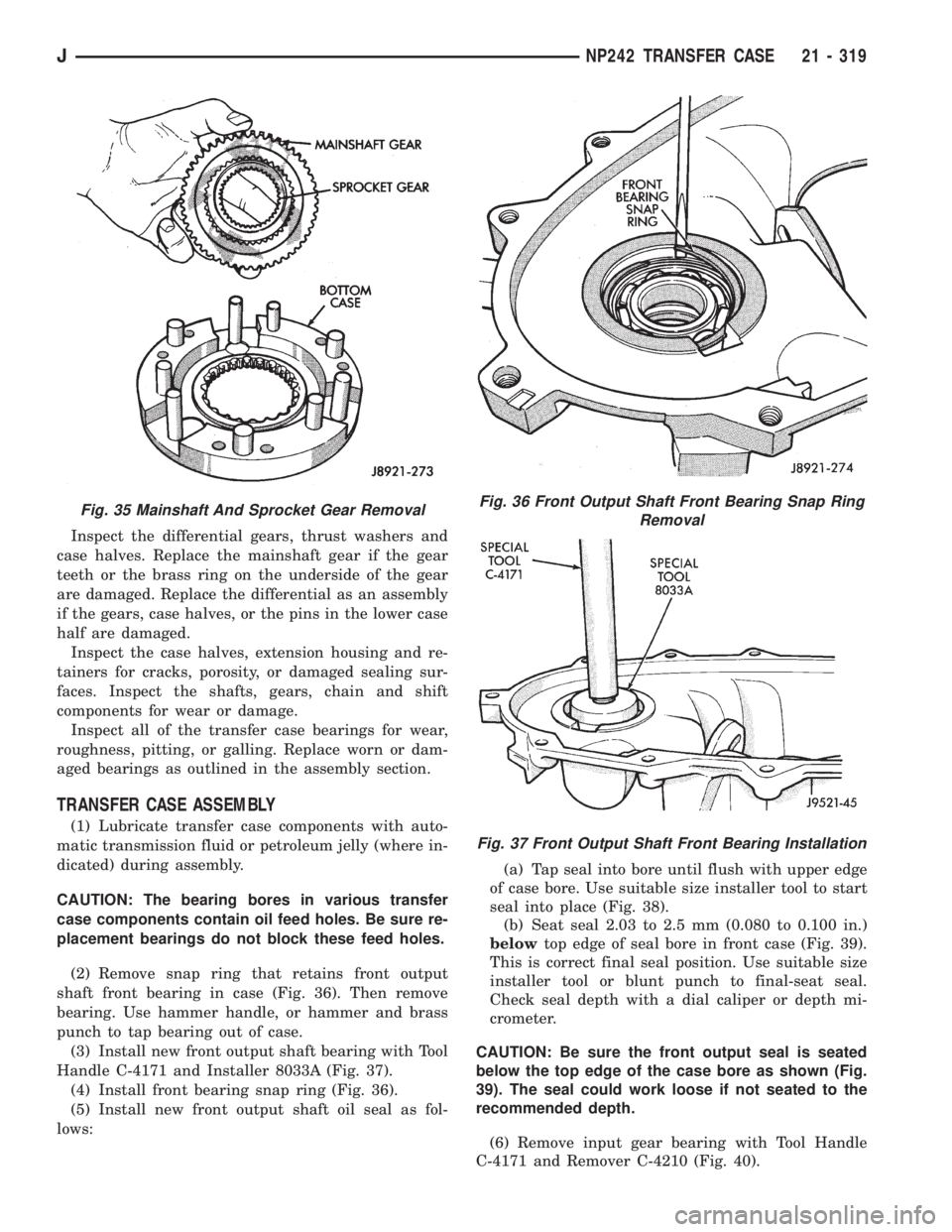
Inspect the differential gears, thrust washers and
case halves. Replace the mainshaft gear if the gear
teeth or the brass ring on the underside of the gear
are damaged. Replace the differential as an assembly
if the gears, case halves, or the pins in the lower case
half are damaged.
Inspect the case halves, extension housing and re-
tainers for cracks, porosity, or damaged sealing sur-
faces. Inspect the shafts, gears, chain and shift
components for wear or damage.
Inspect all of the transfer case bearings for wear,
roughness, pitting, or galling. Replace worn or dam-
aged bearings as outlined in the assembly section.
TRANSFER CASE ASSEMBLY
(1) Lubricate transfer case components with auto-
matic transmission fluid or petroleum jelly (where in-
dicated) during assembly.
CAUTION: The bearing bores in various transfer
case components contain oil feed holes. Be sure re-
placement bearings do not block these feed holes.
(2) Remove snap ring that retains front output
shaft front bearing in case (Fig. 36). Then remove
bearing. Use hammer handle, or hammer and brass
punch to tap bearing out of case.
(3) Install new front output shaft bearing with Tool
Handle C-4171 and Installer 8033A (Fig. 37).
(4) Install front bearing snap ring (Fig. 36).
(5) Install new front output shaft oil seal as fol-
lows:(a) Tap seal into bore until flush with upper edge
of case bore. Use suitable size installer tool to start
seal into place (Fig. 38).
(b) Seat seal 2.03 to 2.5 mm (0.080 to 0.100 in.)
belowtop edge of seal bore in front case (Fig. 39).
This is correct final seal position. Use suitable size
installer tool or blunt punch to final-seat seal.
Check seal depth with a dial caliper or depth mi-
crometer.
CAUTION: Be sure the front output seal is seated
below the top edge of the case bore as shown (Fig.
39). The seal could work loose if not seated to the
recommended depth.
(6) Remove input gear bearing with Tool Handle
C-4171 and Remover C-4210 (Fig. 40).
Fig. 35 Mainshaft And Sprocket Gear RemovalFig. 36 Front Output Shaft Front Bearing Snap Ring
Removal
Fig. 37 Front Output Shaft Front Bearing Installation
JNP242 TRANSFER CASE 21 - 319
Page 1697 of 2198
(7) Install snap ring on new input gear bearing.
(8) Install new input gear bearing with shop press
and wood block. Install bearing far enough to seat
snap ring against case (Fig. 41).
(9) Remove input gear pilot bearing with slide
hammer and internal puller (Fig. 42).
Fig. 38 Starting Front Output Shaft Seal Into Case
Bore
Fig. 39 Front Output Seal Installation Depth
Fig. 40 Input Gear Bearing Removal
Fig. 41 Seating Input Gear Bearing
Fig. 42 Input Gear Pilot Bearing Removal
21 - 320 NP242 TRANSFER CASEJ
Page 1703 of 2198
(40) Install mode sleeve in mode fork (Fig. 63).
Then install assembled sleeve and fork on mainshaft.
Be sure mode sleeve splines are engaged in differen-
tial splines.
(41) Install mode fork and mainshaft assembly in
case (Fig. 64). Rotate mainshaft slightly to engage
shaft with low range gears.
(42) Rotate mode fork pin into shift sector slot.
(43) Install shift rail (Fig. 65).Be sure rail is
seated in both shift forks.
(44) Rotate shift sector to align lockpin hole in low
range fork with access hole in case.
(45) Insert an easy-out in range fork lockpin to
hold it securely for installation (Fig. 66).Lockpin is
slightly tapered on one end. Insert tapered end
into fork and rail.
Fig. 63 Installing Mode Fork And Sleeve
Fig. 64 Assembled Mainshaft And Mode Fork
Installation
Fig. 65 Shift Rail Installation
21 - 326 NP242 TRANSFER CASEJ