1995 JEEP CHEROKEE seat
[x] Cancel search: seatPage 1825 of 2198
INSPECTION
Inspect the rear shoulder/lap belts and buckles. Re-
place any belt that is either cut, frayed, torn or dam-
aged in any way. Replace the shoulder belt if the
retractor is damaged or inoperative.
INSTALLATION
(1) Position the shoulder belt buckle and the lap
belt/buckle anchor plates on the floor panel.
(2) Install the anchor bolts. Tighten the bolts to 37
Nzm (27 ft-lbs) torque.
(3) Position the shoulder belt at the roof rail and
install the upper anchor bolt. Tighten the bolt to 37
Nzm (27 ft-lbs) torque.
(4) Route the shoulder belt through the quarter
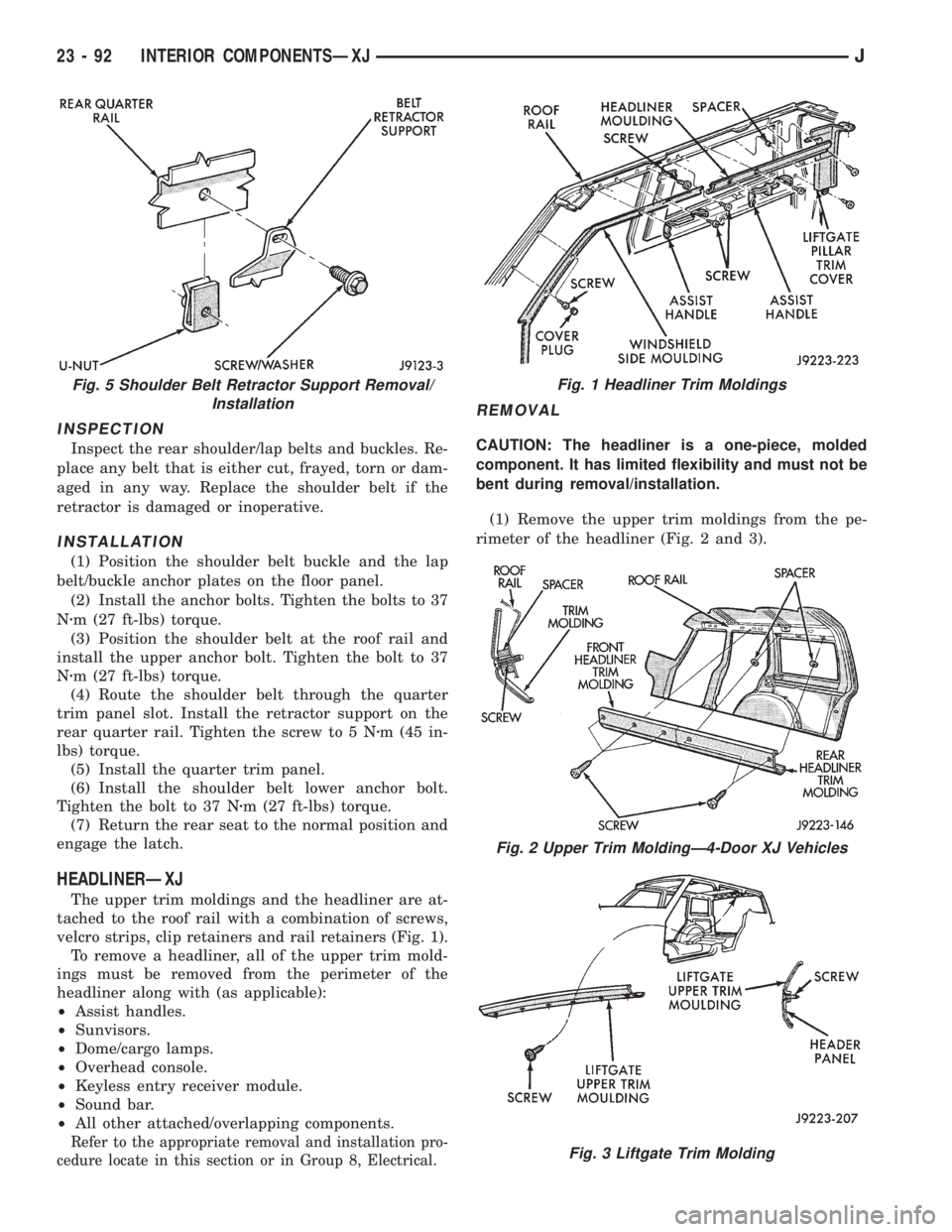
trim panel slot. Install the retractor support on the
rear quarter rail. Tighten the screw to 5 Nzm (45 in-
lbs) torque.
(5) Install the quarter trim panel.
(6) Install the shoulder belt lower anchor bolt.
Tighten the bolt to 37 Nzm (27 ft-lbs) torque.
(7) Return the rear seat to the normal position and
engage the latch.
HEADLINERÐXJ
The upper trim moldings and the headliner are at-
tached to the roof rail with a combination of screws,
velcro strips, clip retainers and rail retainers (Fig. 1).
To remove a headliner, all of the upper trim mold-
ings must be removed from the perimeter of the
headliner along with (as applicable):
²Assist handles.
²Sunvisors.
²Dome/cargo lamps.
²Overhead console.
²Keyless entry receiver module.
²Sound bar.
²All other attached/overlapping components.
Refer to the appropriate removal and installation pro-
cedure locate in this section or in Group 8, Electrical.
REMOVAL
CAUTION: The headliner is a one-piece, molded
component. It has limited flexibility and must not be
bent during removal/installation.
(1) Remove the upper trim moldings from the pe-
rimeter of the headliner (Fig. 2 and 3).
Fig. 5 Shoulder Belt Retractor Support Removal/
InstallationFig. 1 Headliner Trim Moldings
Fig. 2 Upper Trim MoldingÐ4-Door XJ Vehicles
Fig. 3 Liftgate Trim Molding
23 - 92 INTERIOR COMPONENTSÐXJJ
Page 1830 of 2198
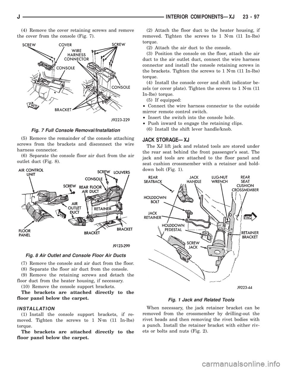
(4) Remove the cover retaining screws and remove
the cover from the console (Fig. 7).
(5) Remove the remainder of the console attaching
screws from the brackets and disconnect the wire
harness connector.
(6) Separate the console floor air duct from the air
outlet duct (Fig. 8).
(7) Remove the console and air duct from the floor.
(8) Separate the floor air duct from the console.
(9) Remove the retaining screws and detach the
floor duct from the heater housing, if necessary.
(10) Remove the console support brackets.
The brackets are attached directly to the
floor panel below the carpet.
INSTALLATION
(1) Install the console support brackets, if re-
moved. Tighten the screws to 1 Nzm (11 In-lbs)
torque.
The brackets are attached directly to the
floor panel below the carpet.(2) Attach the floor duct to the heater housing, if
removed. Tighten the screws to 1 Nzm (11 In-lbs)
torque.
(2) Attach the air duct to the console.
(3) Position the console on the floor, attach the air
duct to the air outlet duct, connect the wire harness
connector and install the console retaining screws in
the brackets. Tighten the screws to 1 Nzm (11 In-lbs)
torque.
(4) Install the console cover and shift indicator be-
zels (or cover plate). Tighten the screws to 1 Nzm(11
In-lbs) torque.
(5) If equipped:
²Connect the wire harness connector to the outside
mirror remote control switch.
²Insert the switch into the console hole.
²Push inward to engage the retaining clips.
(6) Install the shift lever handle/knob.
JACK STORAGEÐXJ
The XJ lift jack and related tools are stored under
the rear seat behind the front passenger's seat. The
jack and tools are attached to the floor panel and
seat cushion crossmember with a retainer and hold-
down bolt (Fig. 1).
When necessary, the jack retainer bracket can be
removed from the crossmember by drilling-out the
rivet heads and then removing the rivet bodies with
a punch. Install the retainer bracket with either riv-
ets or bolts and nuts (Fig. 2).
Fig. 7 Full Console Removal/Installation
Fig. 8 Air Outlet and Console Floor Air Ducts
Fig. 1 Jack and Related Tools
JINTERIOR COMPONENTSÐXJ 23 - 97
Page 1832 of 2198
CARPETS AND FLOOR MATSÐXJ
The carpets/mats are retained around the perime-
ter of the floor panel by the interior trim moldings
and trim panels. To remove a carpet/mat, all of the
retaining trim moldings and panels must be removed
along with all the interfering components (as appli-
cable):
²Seat(s).
²Parking brake lever cover.
²Floor console.
²Transmission and transfer case (if equipped) floor
shift cover/boot.
If necessary, refer to the applicable removal proce-
dure(s) within this manual.
FRONT CARPET/MATÐXJ
REMOVAL
(1) Remove the door sill inner scuff plates.
(2) Remove the front and rear seats (as applicable).
(3) As necessary, remove the trim panels and mold-
ings.
(4) Remove all other interfering components.
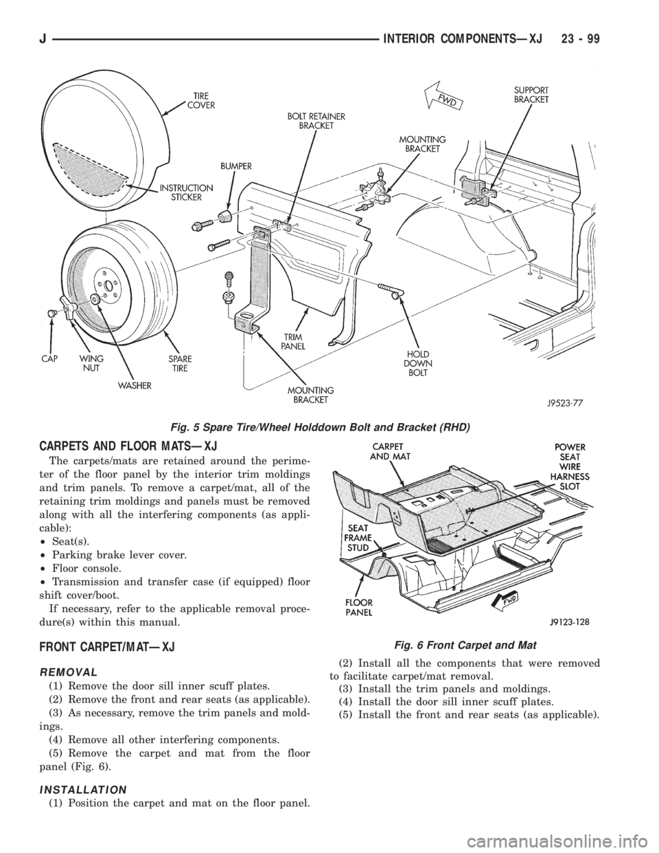
(5) Remove the carpet and mat from the floor
panel (Fig. 6).
INSTALLATION
(1) Position the carpet and mat on the floor panel.(2) Install all the components that were removed
to facilitate carpet/mat removal.
(3) Install the trim panels and moldings.
(4) Install the door sill inner scuff plates.
(5) Install the front and rear seats (as applicable).
Fig. 5 Spare Tire/Wheel Holddown Bolt and Bracket (RHD)
Fig. 6 Front Carpet and Mat
JINTERIOR COMPONENTSÐXJ 23 - 99
Page 1834 of 2198
CARGO BARRIERÐXJ
REMOVAL
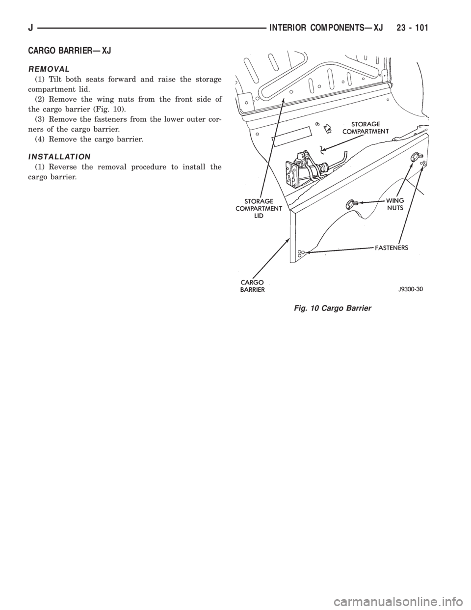
(1) Tilt both seats forward and raise the storage
compartment lid.
(2) Remove the wing nuts from the front side of
the cargo barrier (Fig. 10).
(3) Remove the fasteners from the lower outer cor-
ners of the cargo barrier.
(4) Remove the cargo barrier.
INSTALLATION
(1) Reverse the removal procedure to install the
cargo barrier.
Fig. 10 Cargo Barrier
JINTERIOR COMPONENTSÐXJ 23 - 101
Page 1854 of 2198
(3) Position the replacement nameplate on the
panel and apply inward force to seat it.
FUEL FILLER PROTECTOR/NOZZLEÐYJ
REMOVAL
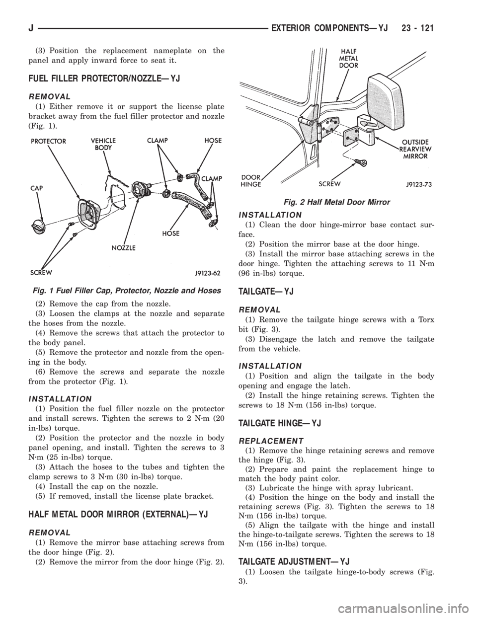
(1) Either remove it or support the license plate
bracket away from the fuel filler protector and nozzle
(Fig. 1).
(2) Remove the cap from the nozzle.
(3) Loosen the clamps at the nozzle and separate
the hoses from the nozzle.
(4) Remove the screws that attach the protector to
the body panel.
(5) Remove the protector and nozzle from the open-
ing in the body.
(6) Remove the screws and separate the nozzle
from the protector (Fig. 1).
INSTALLATION
(1) Position the fuel filler nozzle on the protector
and install screws. Tighten the screws to 2 Nzm (20
in-lbs) torque.
(2) Position the protector and the nozzle in body
panel opening, and install. Tighten the screws to 3
Nzm (25 in-lbs) torque.
(3) Attach the hoses to the tubes and tighten the
clamp screws to 3 Nzm (30 in-lbs) torque.
(4) Install the cap on the nozzle.
(5) If removed, install the license plate bracket.
HALF METAL DOOR MIRROR (EXTERNAL)ÐYJ
REMOVAL
(1) Remove the mirror base attaching screws from
the door hinge (Fig. 2).
(2) Remove the mirror from the door hinge (Fig. 2).
INSTALLATION
(1) Clean the door hinge-mirror base contact sur-
face.
(2) Position the mirror base at the door hinge.
(3) Install the mirror base attaching screws in the
door hinge. Tighten the attaching screws to 11 Nzm
(96 in-lbs) torque.
TAILGATEÐYJ
REMOVAL
(1) Remove the tailgate hinge screws with a Torx
bit (Fig. 3).
(3) Disengage the latch and remove the tailgate
from the vehicle.
INSTALLATION
(1) Position and align the tailgate in the body
opening and engage the latch.
(2) Install the hinge retaining screws. Tighten the
screws to 18 Nzm (156 in-lbs) torque.
TAILGATE HINGEÐYJ
REPLACEMENT
(1) Remove the hinge retaining screws and remove
the hinge (Fig. 3).
(2) Prepare and paint the replacement hinge to
match the body paint color.
(3) Lubricate the hinge with spray lubricant.
(4) Position the hinge on the body and install the
retaining screws (Fig. 3). Tighten the screws to 18
Nzm (156 in-lbs) torque.
(5) Align the tailgate with the hinge and install
the hinge-to-tailgate screws. Tighten the screws to 18
Nzm (156 in-lbs) torque.
TAILGATE ADJUSTMENTÐYJ
(1) Loosen the tailgate hinge-to-body screws (Fig.
3).
Fig. 1 Fuel Filler Cap, Protector, Nozzle and Hoses
Fig. 2 Half Metal Door Mirror
JEXTERIOR COMPONENTSÐYJ 23 - 121
Page 1859 of 2198
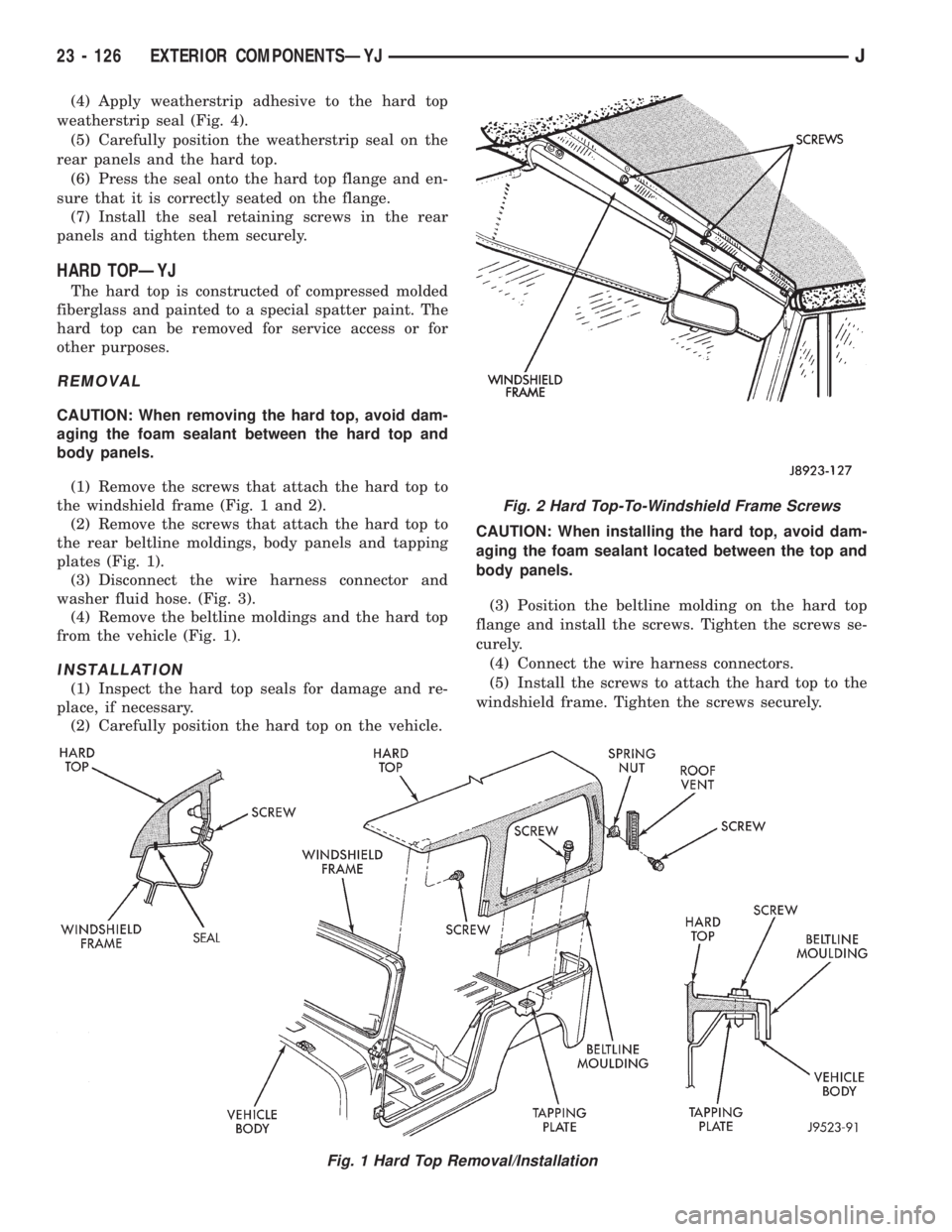
(4) Apply weatherstrip adhesive to the hard top
weatherstrip seal (Fig. 4).
(5) Carefully position the weatherstrip seal on the
rear panels and the hard top.
(6) Press the seal onto the hard top flange and en-
sure that it is correctly seated on the flange.
(7) Install the seal retaining screws in the rear
panels and tighten them securely.
HARD TOPÐYJ
The hard top is constructed of compressed molded
fiberglass and painted to a special spatter paint. The
hard top can be removed for service access or for
other purposes.
REMOVAL
CAUTION: When removing the hard top, avoid dam-
aging the foam sealant between the hard top and
body panels.
(1) Remove the screws that attach the hard top to
the windshield frame (Fig. 1 and 2).
(2) Remove the screws that attach the hard top to
the rear beltline moldings, body panels and tapping
plates (Fig. 1).
(3) Disconnect the wire harness connector and
washer fluid hose. (Fig. 3).
(4) Remove the beltline moldings and the hard top
from the vehicle (Fig. 1).
INSTALLATION
(1) Inspect the hard top seals for damage and re-
place, if necessary.
(2) Carefully position the hard top on the vehicle.CAUTION: When installing the hard top, avoid dam-
aging the foam sealant located between the top and
body panels.
(3) Position the beltline molding on the hard top
flange and install the screws. Tighten the screws se-
curely.
(4) Connect the wire harness connectors.
(5) Install the screws to attach the hard top to the
windshield frame. Tighten the screws securely.
Fig. 1 Hard Top Removal/Installation
Fig. 2 Hard Top-To-Windshield Frame Screws
23 - 126 EXTERIOR COMPONENTSÐYJJ
Page 1875 of 2198
DOOR WEATHERSTRIP SEAL REPLACEMENTÐYJ
REMOVAL
(1) Carefully remove the weatherstrip seal from
the door with a weatherstrip seal removal tool. Pry
the seal outward to separate the plastic retainers
from the door panel holes.
(2) Remove the upper portion of the seal from the
door upper frame with your fingers or a wooden
wand.
(3) Remove the dust and residual adhesive from
the door panel and body panel.
INSTALLATION
(1) Apply adhesive to the front, rear and bottom
edges of the door from the beltline downward.
(2) Install the upper front corner of the seal on the
door first using your fingers or a wooden wand to po-
sition the seal in the channel. Place the inner shoul-
der of the seal in the channel-to-window frame above
the beltline.
(3) Force the retainers, starting at the rear edge of
the door, into the door panel holes.
(4) Ensure that the seal is completely seated
around the door.
BELTLINE SEALÐYJ
REMOVAL
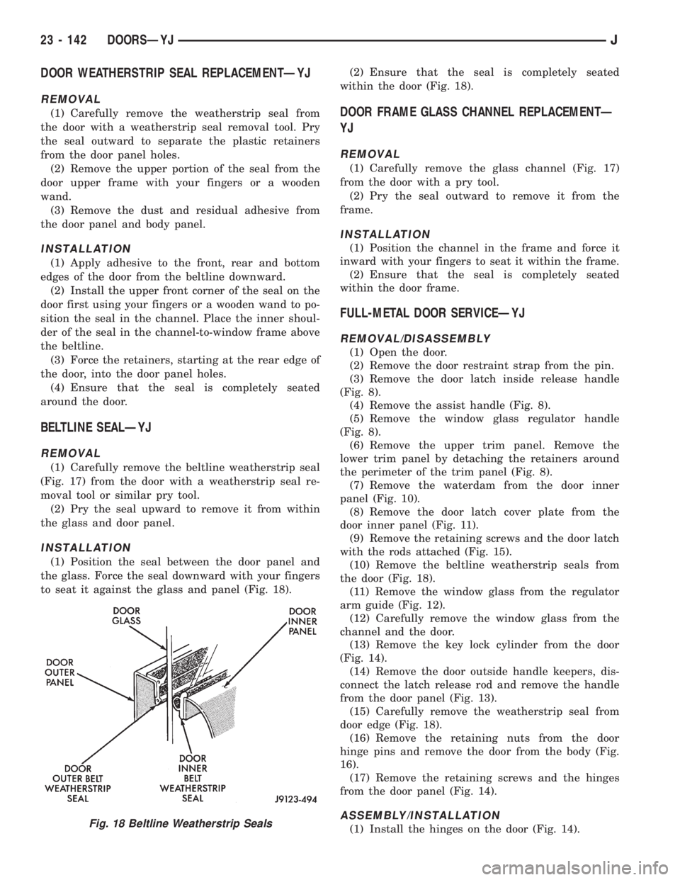
(1) Carefully remove the beltline weatherstrip seal
(Fig. 17) from the door with a weatherstrip seal re-
moval tool or similar pry tool.
(2) Pry the seal upward to remove it from within
the glass and door panel.
INSTALLATION
(1) Position the seal between the door panel and
the glass. Force the seal downward with your fingers
to seat it against the glass and panel (Fig. 18).(2) Ensure that the seal is completely seated
within the door (Fig. 18).
DOOR FRAME GLASS CHANNEL REPLACEMENTÐ
YJ
REMOVAL
(1) Carefully remove the glass channel (Fig. 17)
from the door with a pry tool.
(2) Pry the seal outward to remove it from the
frame.
INSTALLATION
(1) Position the channel in the frame and force it
inward with your fingers to seat it within the frame.
(2) Ensure that the seal is completely seated
within the door frame.
FULL-METAL DOOR SERVICEÐYJ
REMOVAL/DISASSEMBLY
(1) Open the door.
(2) Remove the door restraint strap from the pin.
(3) Remove the door latch inside release handle
(Fig. 8).
(4) Remove the assist handle (Fig. 8).
(5) Remove the window glass regulator handle
(Fig. 8).
(6) Remove the upper trim panel. Remove the
lower trim panel by detaching the retainers around
the perimeter of the trim panel (Fig. 8).
(7) Remove the waterdam from the door inner
panel (Fig. 10).
(8) Remove the door latch cover plate from the
door inner panel (Fig. 11).
(9) Remove the retaining screws and the door latch
with the rods attached (Fig. 15).
(10) Remove the beltline weatherstrip seals from
the door (Fig. 18).
(11) Remove the window glass from the regulator
arm guide (Fig. 12).
(12) Carefully remove the window glass from the
channel and the door.
(13) Remove the key lock cylinder from the door
(Fig. 14).
(14) Remove the door outside handle keepers, dis-
connect the latch release rod and remove the handle
from the door panel (Fig. 13).
(15) Carefully remove the weatherstrip seal from
door edge (Fig. 18).
(16) Remove the retaining nuts from the door
hinge pins and remove the door from the body (Fig.
16).
(17) Remove the retaining screws and the hinges
from the door panel (Fig. 14).
ASSEMBLY/INSTALLATION
(1) Install the hinges on the door (Fig. 14).Fig. 18 Beltline Weatherstrip Seals
23 - 142 DOORSÐYJJ
Page 1877 of 2198
STATIONARY GLASS
INDEX
page page
Hard Top Quarter Window GlassÐYJ......... 149
Rearview Mirror Retaining BracketÐYJ........ 144
Rearview MirrorÐYJ...................... 144
Stationary Glass Water Leak Detection and
RepairÐYJ........................... 150Windshield Frame Weatherstrip SealÐYJ...... 146
Windshield FrameÐYJ.................... 145
Windshield GlassÐYJ..................... 146
Windshield Reveal MoldingÐYJ............. 144
WINDSHIELD REVEAL MOLDINGÐYJ
REMOVAL
(1) Disengage the reveal molding around the pe-
rimeter of the windshield glass with an appropriate
tool.
(2) Remove the moldings from the windshield
frame.
(3) Inspect the reveal molding retainers. Replace
the molding if it has broken, distorted or ineffective
retainers.
INSTALLATION
(1) Position the reveal moldings on the windshield
frame.
(2) Attach the moldings to the frame by tapping
each molding with a rubber mallet to seat the retain-
ers.
REARVIEW MIRRORÐYJ
REMOVAL/INSTALLATION
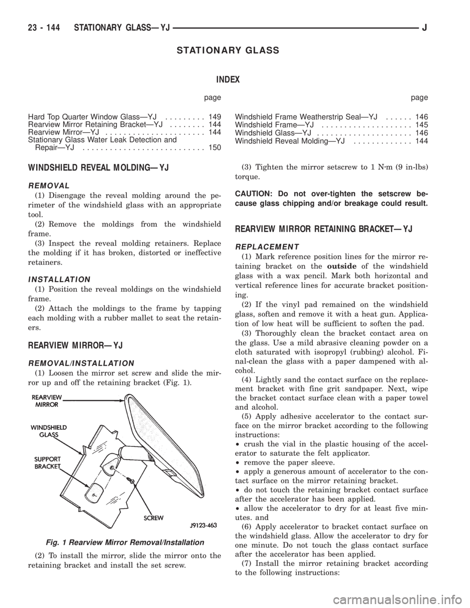
(1) Loosen the mirror set screw and slide the mir-
ror up and off the retaining bracket (Fig. 1).
(2) To install the mirror, slide the mirror onto the
retaining bracket and install the set screw.(3) Tighten the mirror setscrew to 1 Nzm (9 in-lbs)
torque.
CAUTION: Do not over-tighten the setscrew be-
cause glass chipping and/or breakage could result.
REARVIEW MIRROR RETAINING BRACKETÐYJ
REPLACEMENT
(1) Mark reference position lines for the mirror re-
taining bracket on theoutsideof the windshield
glass with a wax pencil. Mark both horizontal and
vertical reference lines for accurate bracket position-
ing.
(2) If the vinyl pad remained on the windshield
glass, soften and remove it with a heat gun. Applica-
tion of low heat will be sufficient to soften the pad.
(3) Thoroughly clean the bracket contact area on
the glass. Use a mild abrasive cleaning powder on a
cloth saturated with isopropyl (rubbing) alcohol. Fi-
nal-clean the glass with a paper dampened with al-
cohol.
(4) Lightly sand the contact surface on the replace-
ment bracket with fine grit sandpaper. Next, wipe
the bracket contact surface clean with a paper towel
and alcohol.
(5) Apply adhesive accelerator to the contact sur-
face on the mirror bracket according to the following
instructions:
²crush the vial in the plastic housing of the accel-
erator to saturate the felt applicator.
²remove the paper sleeve.
²apply a generous amount of accelerator to the con-
tact surface on the mirror retaining bracket.
²do not touch the retaining bracket contact surface
after the accelerator has been applied.
²allow the accelerator to dry for at least five min-
utes. and
(6) Apply accelerator to bracket contact surface on
the windshield glass. Allow the accelerator to dry for
one minute. Do not touch the glass contact surface
after the accelerator has been applied.
(7) Install the mirror retaining bracket according
to the following instructions:
Fig. 1 Rearview Mirror Removal/Installation
23 - 144 STATIONARY GLASSÐYJJ