Page 1770 of 2198
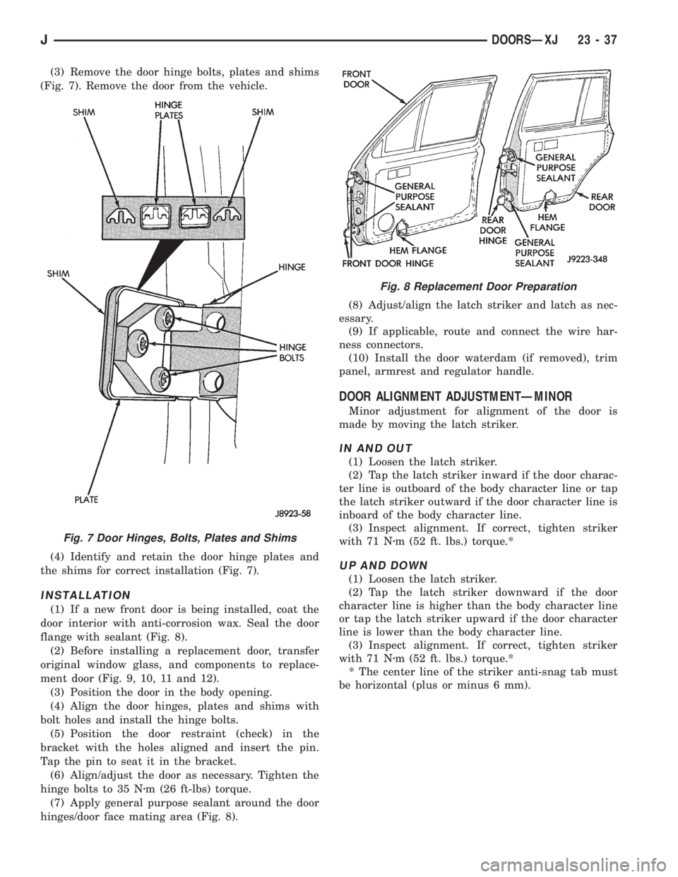
(3) Remove the door hinge bolts, plates and shims
(Fig. 7). Remove the door from the vehicle.
(4) Identify and retain the door hinge plates and
the shims for correct installation (Fig. 7).
INSTALLATION
(1) If a new front door is being installed, coat the
door interior with anti-corrosion wax. Seal the door
flange with sealant (Fig. 8).
(2) Before installing a replacement door, transfer
original window glass, and components to replace-
ment door (Fig. 9, 10, 11 and 12).
(3) Position the door in the body opening.
(4) Align the door hinges, plates and shims with
bolt holes and install the hinge bolts.
(5) Position the door restraint (check) in the
bracket with the holes aligned and insert the pin.
Tap the pin to seat it in the bracket.
(6) Align/adjust the door as necessary. Tighten the
hinge bolts to 35 Nzm (26 ft-lbs) torque.
(7) Apply general purpose sealant around the door
hinges/door face mating area (Fig. 8).(8) Adjust/align the latch striker and latch as nec-
essary.
(9) If applicable, route and connect the wire har-
ness connectors.
(10) Install the door waterdam (if removed), trim
panel, armrest and regulator handle.
DOOR ALIGNMENT ADJUSTMENTÐMINOR
Minor adjustment for alignment of the door is
made by moving the latch striker.
IN AND OUT
(1) Loosen the latch striker.
(2) Tap the latch striker inward if the door charac-
ter line is outboard of the body character line or tap
the latch striker outward if the door character line is
inboard of the body character line.
(3) Inspect alignment. If correct, tighten striker
with 71 Nzm (52 ft. lbs.) torque.*
UP AND DOWN
(1) Loosen the latch striker.
(2) Tap the latch striker downward if the door
character line is higher than the body character line
or tap the latch striker upward if the door character
line is lower than the body character line.
(3) Inspect alignment. If correct, tighten striker
with 71 Nzm (52 ft. lbs.) torque.*
* The center line of the striker anti-snag tab must
be horizontal (plus or minus 6 mm).
Fig. 7 Door Hinges, Bolts, Plates and Shims
Fig. 8 Replacement Door Preparation
JDOORSÐXJ 23 - 37
Page 1785 of 2198
DOOR HINGE/HINGE PIN REPLACEMENTÐXJ
REMOVAL
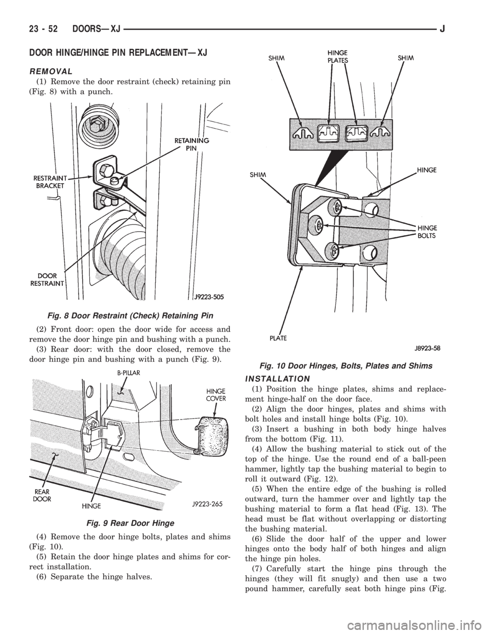
(1) Remove the door restraint (check) retaining pin
(Fig. 8) with a punch.
(2) Front door: open the door wide for access and
remove the door hinge pin and bushing with a punch.
(3) Rear door: with the door closed, remove the
door hinge pin and bushing with a punch (Fig. 9).
(4) Remove the door hinge bolts, plates and shims
(Fig. 10).
(5) Retain the door hinge plates and shims for cor-
rect installation.
(6) Separate the hinge halves.
INSTALLATION
(1) Position the hinge plates, shims and replace-
ment hinge-half on the door face.
(2) Align the door hinges, plates and shims with
bolt holes and install hinge bolts (Fig. 10).
(3) Insert a bushing in both body hinge halves
from the bottom (Fig. 11).
(4) Allow the bushing material to stick out of the
top of the hinge. Use the round end of a ball-peen
hammer, lightly tap the bushing material to begin to
roll it outward (Fig. 12).
(5) When the entire edge of the bushing is rolled
outward, turn the hammer over and lightly tap the
bushing material to form a flat head (Fig. 13). The
head must be flat without overlapping or distorting
the bushing material.
(6) Slide the door half of the upper and lower
hinges onto the body half of both hinges and align
the hinge pin holes.
(7) Carefully start the hinge pins through the
hinges (they will fit snugly) and then use a two
pound hammer, carefully seat both hinge pins (Fig.
Fig. 8 Door Restraint (Check) Retaining Pin
Fig. 9 Rear Door Hinge
Fig. 10 Door Hinges, Bolts, Plates and Shims
23 - 52 DOORSÐXJJ
Page 1787 of 2198
(3) Lower spacer block: install the screws in the
door face. Tighten the screws to 1 Nzm (11 in-lbs)
torque.
DOOR EDGE GUARD/EDGE PROTECTOR
STRIPÐXJ
REPLACEMENT
(1) Pull outward and remove the door edge guard
strip from the door edge (Fig. 3).
(2) Position the door edge guard strip on the door
edge.
(3) Force the door edge guard strip inward until it
is seated on the door edge.
DOOR WINDOW EXTERIOR MOLDINGSÐXJ
REMOVAL
(1) When removing the front or rear door window
exterior molding, open the window completely (Fig. 4
and 5).
(2) Pry and pull the molding sections from the door
panel flange and clips.
Fig. 3 Door Edge Guard/Protector Strip
Fig. 4 Front Door Window Exterior Molding
Fig. 2 Front Door Lower Spacer BlockÐTwo-Door
Vehicles
23 - 54 DOORSÐXJJ
Page 1788 of 2198
INSTALLATION
(1) When installing window moldings, start at the
forward end of the upper molding.
(2) Force the molding onto the door panel and con-
tinue rearward until it is completely seated on the
flange.
(3) Mate the rear molding with the upper molding
and force the molding edge inward.
(4) Continue pressing and moving downward to
complete the installation.
(5) Position the lower molding on the clips and
force it downward.
DOOR WINDOW GLASS AND DOOR OPENING
WEATHERSTRIP SEALSÐXJ
REMOVAL
When removing the front or rear door window glass
weatherstrip seals, open the window.
The window weatherstrip seals (Fig. 6 and 7) can
be removed by hand or with the aid of a small putty
knife (or similar tool).
Fig. 6 Front Door Window Glass Weatherstrip Seals
Fig. 5 Rear Door Window Exterior Molding
Fig. 7 Rear Door Window Glass Weatherstrip Seals
JDOORSÐXJ 23 - 55
Page 1789 of 2198
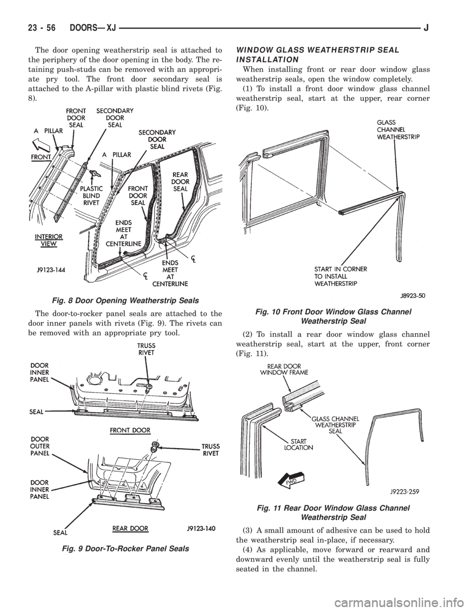
The door opening weatherstrip seal is attached to
the periphery of the door opening in the body. The re-
taining push-studs can be removed with an appropri-
ate pry tool. The front door secondary seal is
attached to the A-pillar with plastic blind rivets (Fig.
8).
The door-to-rocker panel seals are attached to the
door inner panels with rivets (Fig. 9). The rivets can
be removed with an appropriate pry tool.WINDOW GLASS WEATHERSTRIP SEAL
INSTALLATION
When installing front or rear door window glass
weatherstrip seals, open the window completely.
(1) To install a front door window glass channel
weatherstrip seal, start at the upper, rear corner
(Fig. 10).
(2) To install a rear door window glass channel
weatherstrip seal, start at the upper, front corner
(Fig. 11).
(3) A small amount of adhesive can be used to hold
the weatherstrip seal in-place, if necessary.
(4) As applicable, move forward or rearward and
downward evenly until the weatherstrip seal is fully
seated in the channel.
Fig. 8 Door Opening Weatherstrip Seals
Fig. 9 Door-To-Rocker Panel Seals
Fig. 10 Front Door Window Glass Channel
Weatherstrip Seal
Fig. 11 Rear Door Window Glass Channel
Weatherstrip Seal
23 - 56 DOORSÐXJJ
Page 1790 of 2198
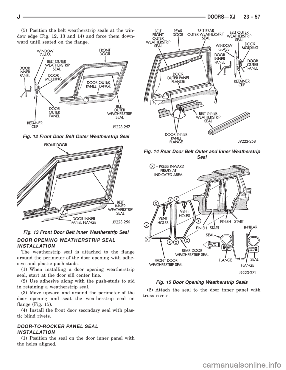
(5) Position the belt weatherstrip seals at the win-
dow edge (Fig. 12, 13 and 14) and force them down-
ward until seated on the flange.
DOOR OPENING WEATHERSTRIP SEAL
INSTALLATION
The weatherstrip seal is attached to the flange
around the perimeter of the door opening with adhe-
sive and plastic push-studs.
(1) When installing a door opening weatherstrip
seal, start at the door sill center line.
(2) Use adhesive along with the push-studs to aid
in retaining a weatherstrip seal.
(3) Move upward and around the perimeter of the
door opening and seat the weatherstrip seal on
flange (Fig. 15).
(4) Install the front door secondary seal with plas-
tic blind rivets.
DOOR-TO-ROCKER PANEL SEAL
INSTALLATION
(1) Position the seal on the door inner panel with
the holes aligned.(2) Attach the seal to the door inner panel with
truss rivets.
Fig. 12 Front Door Belt Outer Weatherstrip Seal
Fig. 13 Front Door Belt Inner Weatherstrip Seal
Fig. 14 Rear Door Belt Outer and Inner Weatherstrip
Seal
Fig. 15 Door Opening Weatherstrip Seals
JDOORSÐXJ 23 - 57
Page 1797 of 2198
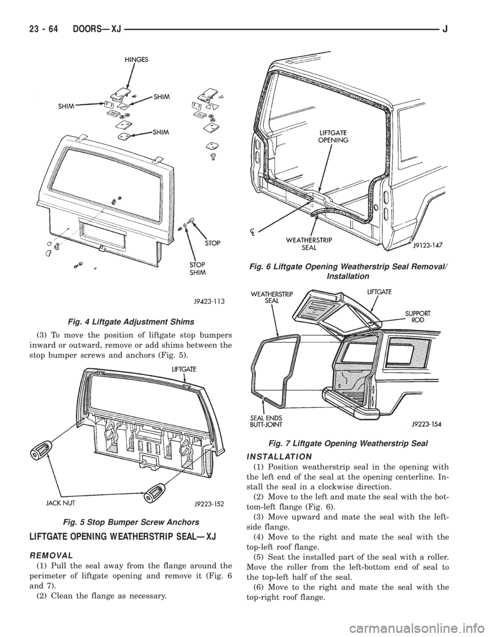
(3) To move the position of liftgate stop bumpers
inward or outward, remove or add shims between the
stop bumper screws and anchors (Fig. 5).
LIFTGATE OPENING WEATHERSTRIP SEALÐXJ
REMOVAL
(1) Pull the seal away from the flange around the
perimeter of liftgate opening and remove it (Fig. 6
and 7).
(2) Clean the flange as necessary.
INSTALLATION
(1) Position weatherstrip seal in the opening with
the left end of the seal at the opening centerline. In-
stall the seal in a clockwise direction.
(2) Move to the left and mate the seal with the bot-
tom-left flange (Fig. 6).
(3) Move upward and mate the seal with the left-
side flange.
(4) Move to the right and mate the seal with the
top-left roof flange.
(5) Seat the installed part of the seal with a roller.
Move the roller from the left-bottom end of seal to
the top-left half of the seal.
(6) Move to the right and mate the seal with the
top-right roof flange.
Fig. 4 Liftgate Adjustment Shims
Fig. 5 Stop Bumper Screw Anchors
Fig. 6 Liftgate Opening Weatherstrip Seal Removal/
Installation
Fig. 7 Liftgate Opening Weatherstrip Seal
23 - 64 DOORSÐXJJ
Page 1798 of 2198
(7) Move downward and mate the seal with the
right-side flange.
(8) Move to the left and mate the seal with the bot-
tom-right flange.
(9) Center and butt seal the ends together at the
centerline.
(10) Seat the remaining part of the seal with a
roller. Move the roller the from top-left half of the
seal to the right-bottom end of the seal.
LIFTGATE LICENSE PLATE LAMP HOUSINGÐXJ
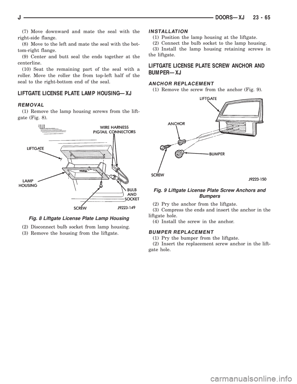
REMOVAL
(1) Remove the lamp housing screws from the lift-
gate (Fig. 8).
(2) Disconnect bulb socket from lamp housing.
(3) Remove the housing from the liftgate.
INSTALLATION
(1) Position the lamp housing at the liftgate.
(2) Connect the bulb socket to the lamp housing.
(3) Install the lamp housing retaining screws in
the liftgate.
LIFTGATE LICENSE PLATE SCREW ANCHOR AND
BUMPERÐXJ
ANCHOR REPLACEMENT
(1) Remove the screw from the anchor (Fig. 9).
(2) Pry the anchor from the liftgate.
(3) Compress the ends and insert the anchor in the
liftgate hole.
(4) Install the screw in the anchor.
BUMPER REPLACEMENT
(1) Pry the bumper from the liftgate.
(2) Insert the replacement screw anchor in the lift-
gate hole.
Fig. 8 Liftgate License Plate Lamp Housing
Fig. 9 Liftgate License Plate Screw Anchors and
Bumpers
JDOORSÐXJ 23 - 65