1995 JEEP CHEROKEE seat
[x] Cancel search: seatPage 1162 of 2198
ments differ by more than 0.0635 mm (0.0025 in.),
ream the guide bore to accommodate an oversize
valve stem.
(7) Compare the measured valve guide bore diam-
eter with specifications (7.95-7.97 mm or 0.313-0.314
inch). If the measurement differs from specification
by more than 0.076 mm (0.003 inch), ream the guide
bore to accommodate an oversize valve stem.
ALTERNATIVE METHOD:
(1) Use a dial indicator to measure the lateral
movement of the valve stem (stem-to-guide clear-
ance). This must be done with the valve installed in
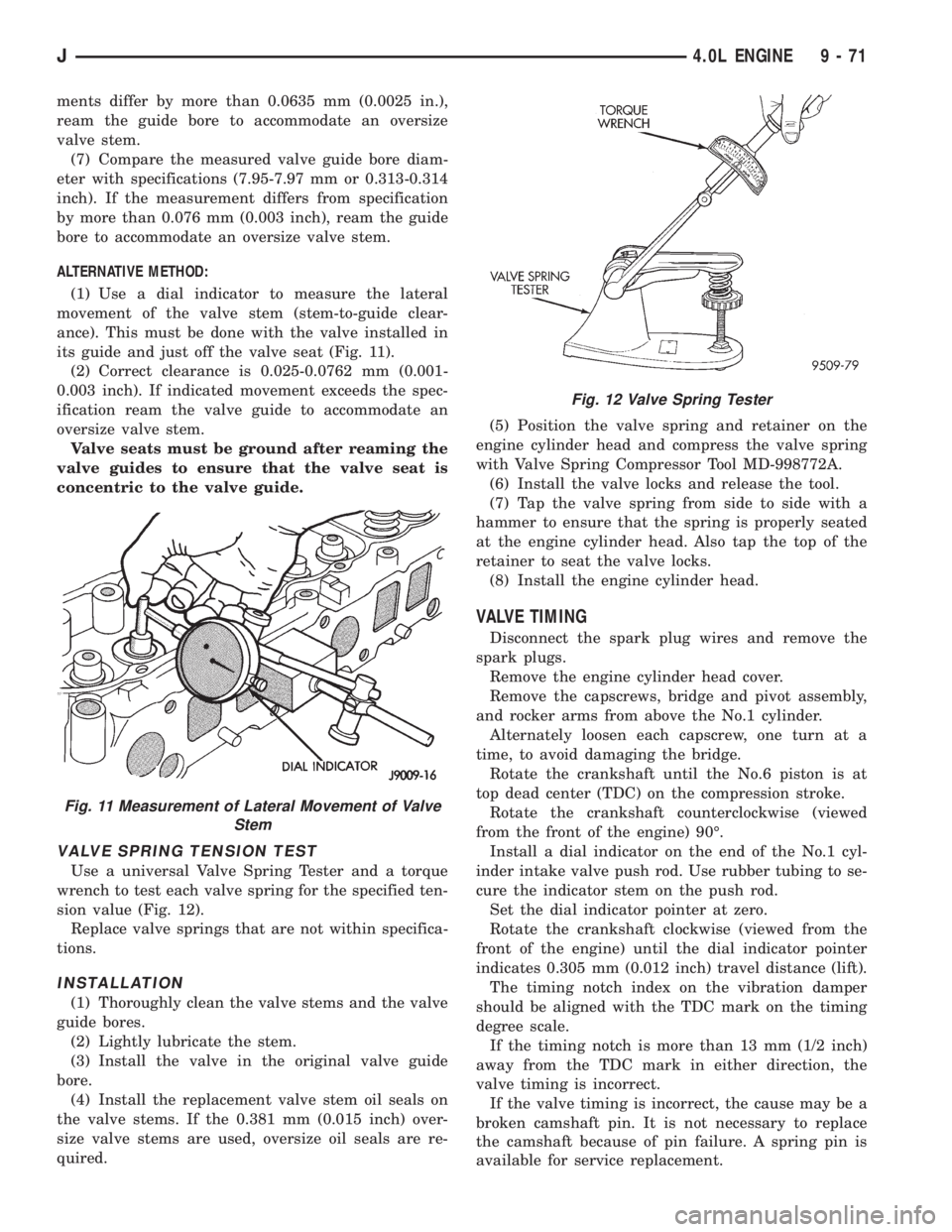
its guide and just off the valve seat (Fig. 11).
(2) Correct clearance is 0.025-0.0762 mm (0.001-
0.003 inch). If indicated movement exceeds the spec-
ification ream the valve guide to accommodate an
oversize valve stem.
Valve seats must be ground after reaming the
valve guides to ensure that the valve seat is
concentric to the valve guide.
VALVE SPRING TENSION TEST
Use a universal Valve Spring Tester and a torque
wrench to test each valve spring for the specified ten-
sion value (Fig. 12).
Replace valve springs that are not within specifica-
tions.
INSTALLATION
(1) Thoroughly clean the valve stems and the valve
guide bores.
(2) Lightly lubricate the stem.
(3) Install the valve in the original valve guide
bore.
(4) Install the replacement valve stem oil seals on
the valve stems. If the 0.381 mm (0.015 inch) over-
size valve stems are used, oversize oil seals are re-
quired.(5) Position the valve spring and retainer on the
engine cylinder head and compress the valve spring
with Valve Spring Compressor Tool MD-998772A.
(6) Install the valve locks and release the tool.
(7) Tap the valve spring from side to side with a
hammer to ensure that the spring is properly seated
at the engine cylinder head. Also tap the top of the
retainer to seat the valve locks.
(8) Install the engine cylinder head.
VALVE TIMING
Disconnect the spark plug wires and remove the
spark plugs.
Remove the engine cylinder head cover.
Remove the capscrews, bridge and pivot assembly,
and rocker arms from above the No.1 cylinder.
Alternately loosen each capscrew, one turn at a
time, to avoid damaging the bridge.
Rotate the crankshaft until the No.6 piston is at
top dead center (TDC) on the compression stroke.
Rotate the crankshaft counterclockwise (viewed
from the front of the engine) 90É.
Install a dial indicator on the end of the No.1 cyl-
inder intake valve push rod. Use rubber tubing to se-
cure the indicator stem on the push rod.
Set the dial indicator pointer at zero.
Rotate the crankshaft clockwise (viewed from the
front of the engine) until the dial indicator pointer
indicates 0.305 mm (0.012 inch) travel distance (lift).
The timing notch index on the vibration damper
should be aligned with the TDC mark on the timing
degree scale.
If the timing notch is more than 13 mm (1/2 inch)
away from the TDC mark in either direction, the
valve timing is incorrect.
If the valve timing is incorrect, the cause may be a
broken camshaft pin. It is not necessary to replace
the camshaft because of pin failure. A spring pin is
available for service replacement.
Fig. 11 Measurement of Lateral Movement of Valve
Stem
Fig. 12 Valve Spring Tester
J4.0L ENGINE 9 - 71
Page 1167 of 2198
(3) Remove the fan and shroud.
(4) Disconnect the radiator overflow tube, radiator
hoses, automatic transmission fluid cooler pipes (if
equipped).
(5) Remove the radiator.
(6) If equipped with air conditioning:
CAUTION: DO NOT loosen or disconnect any air
conditioner system fittings. Move the condenser
and receiver/drier aside as a complete assembly.
(a) Remove the A/C compressor serpentine drive
belt idler pulley.
(b) Disconnect and remove the generator.
(c) Remove the A/C condenser attaching bolts
and move the condenser and receiver/drier assem-
bly up and out of the way.
(7) Remove the serpentine drive belt.
(8) Remove the crankshaft vibration damper.
(9) Remove the timing case cover. Clean the gasket
material from the cover.
(10) Remove the thrust pin and tension spring
from the preload bolt head.
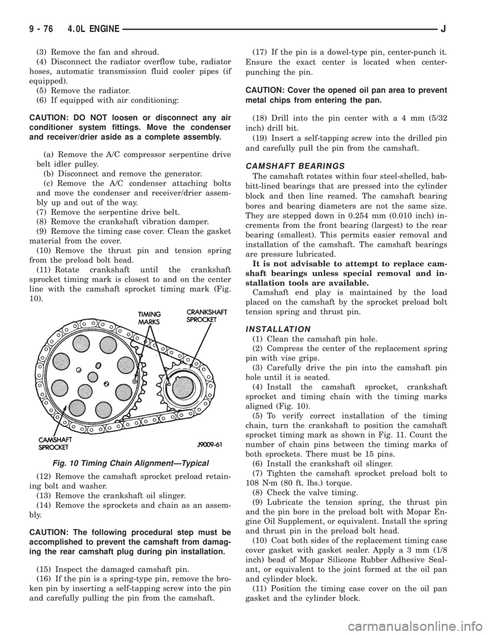
(11) Rotate crankshaft until the crankshaft
sprocket timing mark is closest to and on the center
line with the camshaft sprocket timing mark (Fig.
10).
(12) Remove the camshaft sprocket preload retain-
ing bolt and washer.
(13) Remove the crankshaft oil slinger.
(14) Remove the sprockets and chain as an assem-
bly.
CAUTION: The following procedural step must be
accomplished to prevent the camshaft from damag-
ing the rear camshaft plug during pin installation.
(15) Inspect the damaged camshaft pin.
(16) If the pin is a spring-type pin, remove the bro-
ken pin by inserting a self-tapping screw into the pin
and carefully pulling the pin from the camshaft.(17) If the pin is a dowel-type pin, center-punch it.
Ensure the exact center is located when center-
punching the pin.
CAUTION: Cover the opened oil pan area to prevent
metal chips from entering the pan.
(18) Drill into the pin center witha4mm(5/32
inch) drill bit.
(19) Insert a self-tapping screw into the drilled pin
and carefully pull the pin from the camshaft.
CAMSHAFT BEARINGS
The camshaft rotates within four steel-shelled, bab-
bitt-lined bearings that are pressed into the cylinder
block and then line reamed. The camshaft bearing
bores and bearing diameters are not the same size.
They are stepped down in 0.254 mm (0.010 inch) in-
crements from the front bearing (largest) to the rear
bearing (smallest). This permits easier removal and
installation of the camshaft. The camshaft bearings
are pressure lubricated.
It is not advisable to attempt to replace cam-
shaft bearings unless special removal and in-
stallation tools are available.
Camshaft end play is maintained by the load
placed on the camshaft by the sprocket preload bolt
tension spring and thrust pin.
INSTALLATION
(1) Clean the camshaft pin hole.
(2) Compress the center of the replacement spring
pin with vise grips.
(3) Carefully drive the pin into the camshaft pin
hole until it is seated.
(4) Install the camshaft sprocket, crankshaft
sprocket and timing chain with the timing marks
aligned (Fig. 10).
(5) To verify correct installation of the timing
chain, turn the crankshaft to position the camshaft
sprocket timing mark as shown in Fig. 11. Count the
number of chain pins between the timing marks of
both sprockets. There must be 15 pins.
(6) Install the crankshaft oil slinger.
(7) Tighten the camshaft sprocket preload bolt to
108 Nzm (80 ft. lbs.) torque.
(8) Check the valve timing.
(9) Lubricate the tension spring, the thrust pin
and the pin bore in the preload bolt with Mopar En-
gine Oil Supplement, or equivalent. Install the spring
and thrust pin in the preload bolt head.
(10) Coat both sides of the replacement timing case
cover gasket with gasket sealer. Applya3mm(1/8
inch) bead of Mopar Silicone Rubber Adhesive Seal-
ant, or equivalent to the joint formed at the oil pan
and cylinder block.
(11) Position the timing case cover on the oil pan
gasket and the cylinder block.
Fig. 10 Timing Chain AlignmentÐTypical
9 - 76 4.0L ENGINEJ
Page 1175 of 2198
SIDE CLEARANCE MEASUREMENT
Slide snug-fitting feeler gauge between the connect-
ing rod and crankshaft journal flange. Refer to En-
gine Specifications for the proper clearance. Replace
the connecting rod if the side clearance is not within
specification.
PISTON FITTING
BORE GAUGE METHOD
(1) To correctly select the proper size piston, a cyl-
inder bore gauge, Special Tool 6879 or equivalent, ca-
pable of reading in .00019INCREMENTS with gauge
ring Special Tool 6884 is required. If a bore gauge is
not available, do not use an inside micrometer.
(2) Set the bore gauge to the gauge ring and zero
gauge.
(3) Remove gauge from ring and check cylinder as
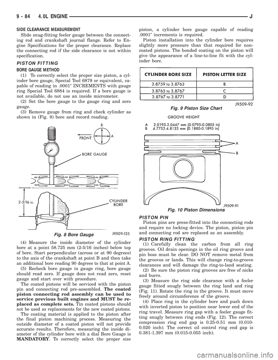
shown in (Fig. 8) bore and record reading.
(4) Measure the inside diameter of the cylinder
bore at a point 58.725 mm (2-5/16 inches) below top
of bore. Start perpendicular (across or at 90 degrees)
to the axis of the crankshaft at point B and then take
an additional bore reading 90 degrees to that at point A.
(5) Recheck bore gauge in gauge ring, bore gauge
should read zero. If gauge does not read zero, reset
gauge and start over with procedure.
The coated pistons will be serviced with the piston
pin and connecting rod pre-assembled.The coated
piston connecting rod assembly can be used to
service previous built engines and MUST be re-
placed as complete sets.Tin coated pistons should
not be used as replacements for the new coated pistons.
The coating material is applied to the piston after
the final piston machining process. Measuring the
outside diameter of a coated piston will not provide
accurate results. Therefore, measuring the inside di-
ameter of the cylinder bore with a dial Bore Gauge is
MANDATORY. To correctly select the proper sizepiston, a cylinder bore gauge capable of reading
.00019increments is required.
Piston installation into the cylinder bore requires
slightly more pressure than that required for non-
coated pistons. The bonded coating on the piston will
give the appearance of a line-to-line fit with the cyl-
inder bore.
PISTON PIN
Piston pins are press-fitted into the connecting rods
and require no locking device. The piston, piston pin
and connecting rod are replaced as an assembly.
PISTON RING FITTING
(1) Carefully clean the carbon from all ring
grooves. Oil drain openings in the oil ring groove and
pin boss must be clear. DO NOT remove metal from
the grooves or lands. This will change ring-to-groove
clearances and will damage the ring-to-land seating.
(2) Be sure the piston ring grooves are free of nicks
and burrs.
(3) Measure the ring side clearance with a feeler
gauge fitted snugly between the ring land and ring
(Fig. 11). Rotate the ring in the groove. It must move
freely around circumference of the groove.
(4) Place ring in the cylinder bore and push down
with inverted piston to position near lower end of the
ring travel. Measure ring gap with a feeler gauge fit-
ting snugly between ring ends (Fig. 12). The correct
compression ring end gap is 0.25-0.51 mm (0.010-
0.020 inch). The correct oil control ring end gap is
0.381-1.397 mm (0.015-0.055 inch).
Fig. 8 Bore Gauge
Fig. 9 Piston Size Chart
Fig. 10 Piston Dimensions
9 - 84 4.0L ENGINEJ
Page 1182 of 2198
REMOVAL
(1) Remove the engine flywheel or converter drive
plate.
(2) Remove the oil pan.
(3) Remove the rear main bearing cap (No.7).
(4) Push the upper seal out of the groove. Ensure
that the crankshaft and seal groove are not damaged.
(5) Remove the lower half of the seal from the
bearing cap.
INSTALLATION
(1) Wipe the seal surface area of the crankshaft
until it is clean.
(2) Apply a thin coat of engine oil.
(3) Coat the lip of the seal with engine oil.
(4) Carefully position the upper seal into the
groove in the cylinder block. The lip of the seal faces
toward the front of the engine.
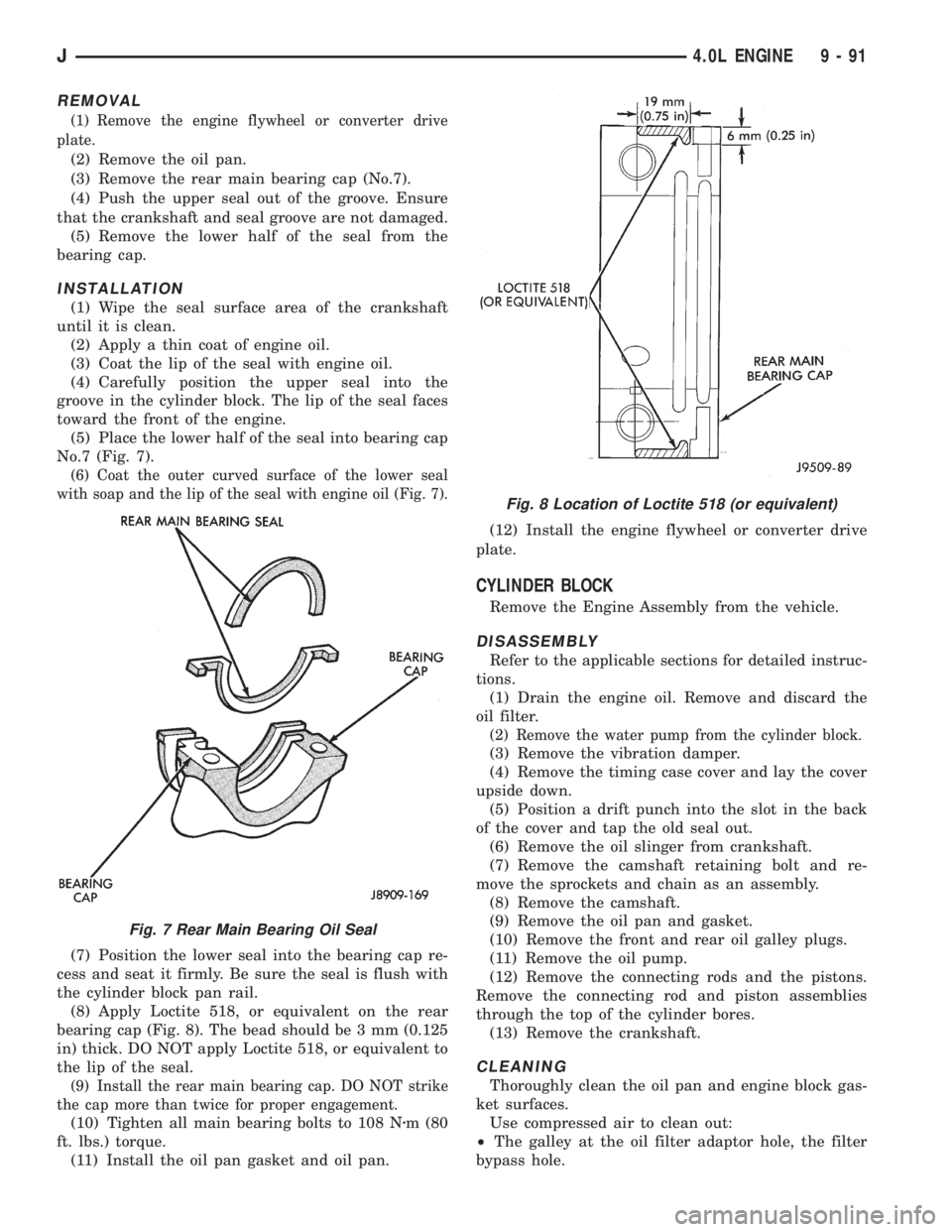
(5) Place the lower half of the seal into bearing cap
No.7 (Fig. 7).
(6) Coat the outer curved surface of the lower seal
with soap and the lip of the seal with engine oil (Fig. 7).
(7) Position the lower seal into the bearing cap re-
cess and seat it firmly. Be sure the seal is flush with
the cylinder block pan rail.
(8) Apply Loctite 518, or equivalent on the rear
bearing cap (Fig. 8). The bead should be 3 mm (0.125
in) thick. DO NOT apply Loctite 518, or equivalent to
the lip of the seal.
(9) Install the rear main bearing cap. DO NOT strike
the cap more than twice for proper engagement.
(10) Tighten all main bearing bolts to 108 Nzm (80
ft. lbs.) torque.
(11) Install the oil pan gasket and oil pan.(12) Install the engine flywheel or converter drive
plate.
CYLINDER BLOCK
Remove the Engine Assembly from the vehicle.
DISASSEMBLY
Refer to the applicable sections for detailed instruc-
tions.
(1) Drain the engine oil. Remove and discard the
oil filter.
(2) Remove the water pump from the cylinder block.
(3) Remove the vibration damper.
(4) Remove the timing case cover and lay the cover
upside down.
(5) Position a drift punch into the slot in the back
of the cover and tap the old seal out.
(6) Remove the oil slinger from crankshaft.
(7) Remove the camshaft retaining bolt and re-
move the sprockets and chain as an assembly.
(8) Remove the camshaft.
(9) Remove the oil pan and gasket.
(10) Remove the front and rear oil galley plugs.
(11) Remove the oil pump.
(12) Remove the connecting rods and the pistons.
Remove the connecting rod and piston assemblies
through the top of the cylinder bores.
(13) Remove the crankshaft.
CLEANING
Thoroughly clean the oil pan and engine block gas-
ket surfaces.
Use compressed air to clean out:
²The galley at the oil filter adaptor hole, the filter
bypass hole.
Fig. 7 Rear Main Bearing Oil Seal
Fig. 8 Location of Loctite 518 (or equivalent)
J4.0L ENGINE 9 - 91
Page 1201 of 2198
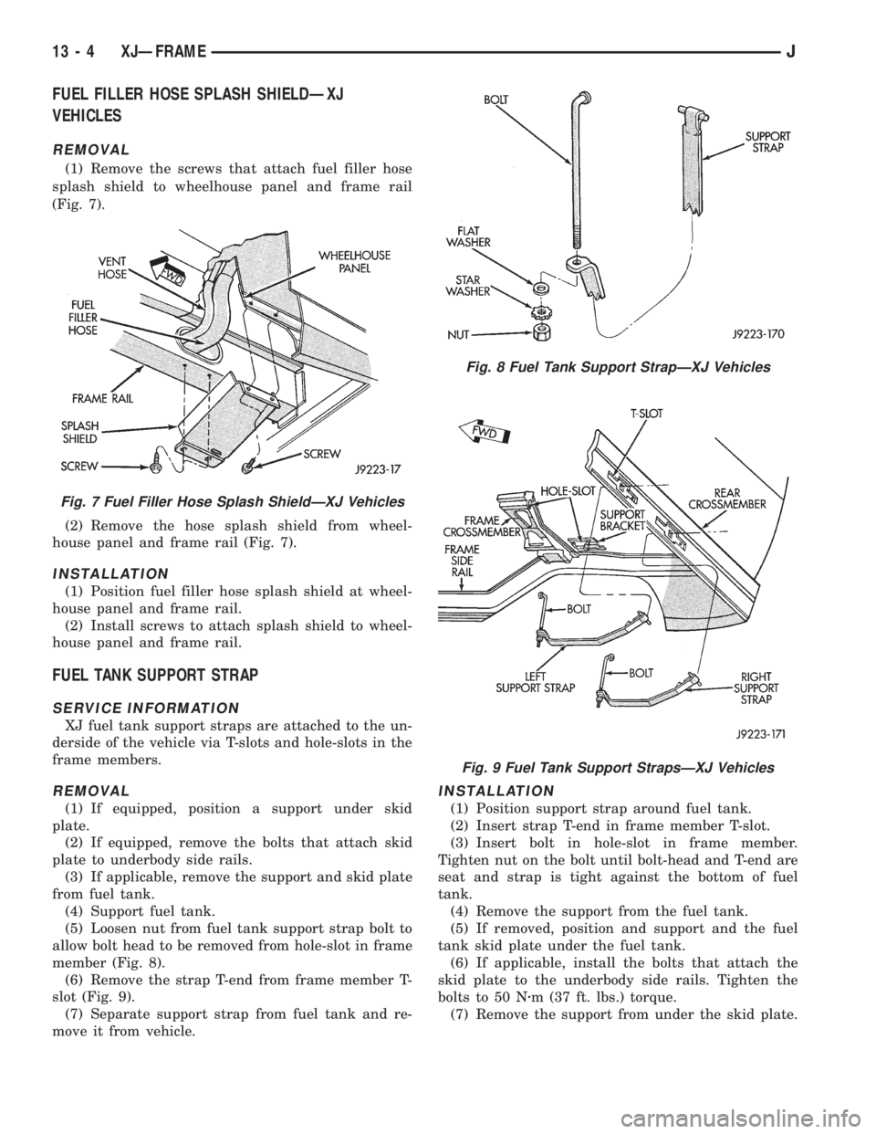
FUEL FILLER HOSE SPLASH SHIELDÐXJ
VEHICLES
REMOVAL
(1) Remove the screws that attach fuel filler hose
splash shield to wheelhouse panel and frame rail
(Fig. 7).
(2) Remove the hose splash shield from wheel-
house panel and frame rail (Fig. 7).
INSTALLATION
(1) Position fuel filler hose splash shield at wheel-
house panel and frame rail.
(2) Install screws to attach splash shield to wheel-
house panel and frame rail.
FUEL TANK SUPPORT STRAP
SERVICE INFORMATION
XJ fuel tank support straps are attached to the un-
derside of the vehicle via T-slots and hole-slots in the
frame members.
REMOVAL
(1) If equipped, position a support under skid
plate.
(2) If equipped, remove the bolts that attach skid
plate to underbody side rails.
(3) If applicable, remove the support and skid plate
from fuel tank.
(4) Support fuel tank.
(5) Loosen nut from fuel tank support strap bolt to
allow bolt head to be removed from hole-slot in frame
member (Fig. 8).
(6) Remove the strap T-end from frame member T-
slot (Fig. 9).
(7) Separate support strap from fuel tank and re-
move it from vehicle.
INSTALLATION
(1) Position support strap around fuel tank.
(2) Insert strap T-end in frame member T-slot.
(3) Insert bolt in hole-slot in frame member.
Tighten nut on the bolt until bolt-head and T-end are
seat and strap is tight against the bottom of fuel
tank.
(4) Remove the support from the fuel tank.
(5) If removed, position and support and the fuel
tank skid plate under the fuel tank.
(6) If applicable, install the bolts that attach the
skid plate to the underbody side rails. Tighten the
bolts to 50 Nzm (37 ft. lbs.) torque.
(7) Remove the support from under the skid plate.
Fig. 7 Fuel Filler Hose Splash ShieldÐXJ Vehicles
Fig. 8 Fuel Tank Support StrapÐXJ Vehicles
Fig. 9 Fuel Tank Support StrapsÐXJ Vehicles
13 - 4 XJÐFRAMEJ
Page 1218 of 2198
FUEL DELIVERY SYSTEM
INDEX
page page
Fuel Filter................................ 9
Fuel Pressure Leak Down Test................ 8
Fuel Pressure Release Procedure.............. 6
Fuel Pump Capacity Test.................... 7
Fuel Pump Electrical Control.................. 5Fuel Pump Module......................... 3
Fuel System Pressure Test................... 6
Fuel Tubes/Lines/Hoses and Clamps............ 9
Quick-Connect Fittings..................... 10
FUEL PUMP MODULE
The fuel pump module is installed in the top of the
fuel tank. The fuel pump module contains the follow-
ing components:
²Electric fuel pump
²Fuel pump reservoir
²In-tank fuel filter
²Fuel gauge sending unit
²Fuel supply and return tube connections
The fuel pump used on all vehicles is a turbine
type pump. It is driven by a permanent magnet 12
volt electric motor that is immersed in the fuel tank.
The electrical pump is integral with the fuel sender
unit. The pump/sender assembly is installed inside
the fuel tank.
The fuel pump has a check valve at the outlet end
that consists of a ball held against a seat by force ap-
plied from a spring. When the pump is operating,
fuel pressure overcomes spring pressure and forces
the ball off its seat, allowing fuel to flow. When the
pump is not operating, spring pressure forces the ball
back against the seat preventing fuel backflow
through the pump.
Fuel system pressure is maintained at approxi-
mately 214 kPa (31 psi). This is when the pump is
operating and vacuum is supplied to the fuel pres-
sure regulator. If vacuum is not supplied to the pres-
sure regulator, fuel pressure will be approximately
55-69 kPa (8-10 psi) higher. This may be due to a
broken or clogged vacuum line. When the fuel pump
is not operating, fuel system pressure of 131-269 kPa
(19-39 psi) is maintained for approximately 2 to 6
hours. This is done by the fuel pump outlet check
valve and the vacuum assisted fuel pressure regula-
tor.
REMOVALÐXJ MODELS
The fuel pump/gauge sender unit assembly can be
removed from the fuel tank without removing the
tank from the vehicle.
WARNING: THE FUEL SYSTEM IS UNDER A CON-
STANT PRESSURE (EVEN WITH THE ENGINE OFF).
BEFORE SERVICING THE FUEL PUMP MODULE,
THE FUEL SYSTEM PRESSURE MUST BE RE-LEASED. REFER TO THE FUEL PRESSURE RE-
LEASE PROCEDURE IN THIS GROUP.
WARNING: EXTINGUISH ALL TOBACCO SMOKING
PRODUCTS BEFORE SERVICING THE FUEL SYS-
TEM. KEEP OPEN FLAME AWAY FROM FUEL SYS-
TEM COMPONENTS.
(1) Remove fuel filler cap. Perform the Fuel Pres-
sure Release Procedure as outlined in this group.
(2) Disconnect negative battery cable.
(3) Using an approved portable gasoline siphon/
storage tank, drain fuel tank until fuel level is below
one quarter (1/4) full.
(4) Raise and support vehicle.
WARNING: WRAP SHOP TOWELS AROUND FUEL
HOSES TO ABSORB ANY FUEL SPILLAGE DURING
FUEL TANK REMOVAL.
(5) Disconnect fuel vent supply and return tubes
from fittings on fuel pump module.
(6) Disconnect fuel pump module electrical harness
connector from main harness.
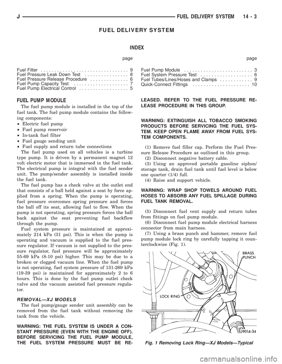
(7) Using a brass punch and hammer, remove fuel
pump module lock ring by carefully tapping it coun-
terclockwise (Fig. 1).
Fig. 1 Removing Lock RingÐXJ ModelsÐTypical
JFUEL DELIVERY SYSTEM 14 - 3
Page 1219 of 2198
(8) Remove fuel pump module and O-ring seal.
Discard old O-ring and fuel pump module inlet filter.
DISASSEMBLYÐXJ MODELS
(1) Remove and discard fuel pump inlet filter.
The wire terminals to the fuel pump motor are dif-
ferent in size and cannot be connected to the wrong
terminal.
(2) Disconnect fuel pump terminal wires.
(3) Remove fuel pump outlet hose and clamp. Re-
place the hose if it shows any signs of fatigue or fail-
ure.
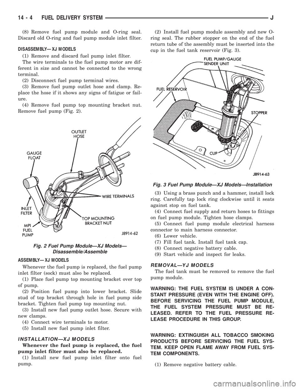
(4) Remove fuel pump top mounting bracket nut.
Remove fuel pump (Fig. 2).
ASSEMBLYÐXJ MODELS
Whenever the fuel pump is replaced, the fuel pump
inlet filter (sock) must also be replaced.
(1) Place fuel pump top mounting bracket over top
of pump.
(2) Position fuel pump into lower bracket. Slide
stud of top bracket through hole in fuel pump side
bracket. Tighten fuel pump top mounting nut.
(3) Install new fuel pump outlet hose. Secure with
new clamps.
(4) Connect wire terminals to motor.
(5) Install new fuel pump inlet filter.
INSTALLATIONÐXJ MODELS
Whenever the fuel pump is replaced, the fuel
pump inlet filter must also be replaced.
(1) Install new fuel pump inlet filter onto fuel
pump.(2) Install fuel pump module assembly and new O-
ring seal. The rubber stopper on the end of the fuel
return tube of the assembly must be inserted into the
cup in the fuel tank reservoir (Fig. 3).
(3) Using a brass punch and a hammer, install lock
ring. Carefully tap lock ring clockwise until it seats
against stop on fuel tank.
(4) Connect fuel supply and return hoses to fittings
on fuel pump module. Tighten hose clamps.
(5) Connect fuel pump module electrical harness
connector to main harness connector.
(6) Lower vehicle.
(7) Fill fuel tank. Install fuel tank cap.
(8) Connect negative battery cable.
(9) Start vehicle and inspect for leaks.
REMOVALÐYJ MODELS
The fuel tank must be removed to remove the fuel
pump module.
WARNING: THE FUEL SYSTEM IS UNDER A CON-
STANT PRESSURE (EVEN WITH THE ENGINE OFF).
BEFORE SERVICING THE FUEL PUMP MODULE,
THE FUEL SYSTEM PRESSURE MUST BE RE-
LEASED. REFER TO THE FUEL PRESSURE RE-
LEASE PROCEDURE IN THIS GROUP.
WARNING: EXTINGUISH ALL TOBACCO SMOKING
PRODUCTS BEFORE SERVICING THE FUEL SYS-
TEM. KEEP OPEN FLAME AWAY FROM FUEL SYS-
TEM COMPONENTS.
(1) Remove negative battery cable.
Fig. 2 Fuel Pump ModuleÐXJ ModelsÐ
Disassemble/Assemble
Fig. 3 Fuel Pump ModuleÐXJ ModelsÐInstallation
14 - 4 FUEL DELIVERY SYSTEMJ
Page 1231 of 2198
(2) Raise skid plate/fuel tank until gauge sender
wire connector can be connected to harness connec-
tor.
(3) Finish raising skid plate/fuel tank assembly
into position. Tighten mounting nuts to 16 Nzm (12
ft. lbs.) torque. Remove transmission jack.
(4) Connect fuel fill hose and fill vent hose to filler
neck. Tighten hose clamps.
(5) Connect vent hose to vent tube.
(6) Connect fuel supply hose to the supply tube
and fuel return hose to return tube. Tighten hose
clamps.
(7) Install fuel filler neck shroud with push clips.
(8) Lower vehicle.
(9) Fill fuel tank. Install filler cap.
(10) Connect negative battery cable to battery.
(11) Start vehicle and inspect for leaks.
FUEL GAUGE SENDING UNIT
The fuel gauge sending unit is attached to the fuel
pump module. Refer to Fuel Pump Module in the
Fuel Delivery System section of this group.
FUEL TANK PRESSURE RELIEF/ROLLOVER VALVE
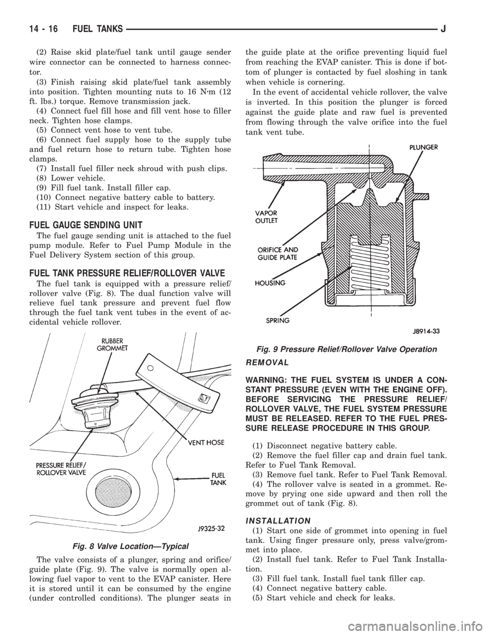
The fuel tank is equipped with a pressure relief/
rollover valve (Fig. 8). The dual function valve will
relieve fuel tank pressure and prevent fuel flow
through the fuel tank vent tubes in the event of ac-
cidental vehicle rollover.
The valve consists of a plunger, spring and orifice/
guide plate (Fig. 9). The valve is normally open al-
lowing fuel vapor to vent to the EVAP canister. Here
it is stored until it can be consumed by the engine
(under controlled conditions). The plunger seats inthe guide plate at the orifice preventing liquid fuel
from reaching the EVAP canister. This is done if bot-
tom of plunger is contacted by fuel sloshing in tank
when vehicle is cornering.
In the event of accidental vehicle rollover, the valve
is inverted. In this position the plunger is forced
against the guide plate and raw fuel is prevented
from flowing through the valve orifice into the fuel
tank vent tube.
REMOVAL
WARNING: THE FUEL SYSTEM IS UNDER A CON-
STANT PRESSURE (EVEN WITH THE ENGINE OFF).
BEFORE SERVICING THE PRESSURE RELIEF/
ROLLOVER VALVE, THE FUEL SYSTEM PRESSURE
MUST BE RELEASED. REFER TO THE FUEL PRES-
SURE RELEASE PROCEDURE IN THIS GROUP.
(1) Disconnect negative battery cable.
(2) Remove the fuel filler cap and drain fuel tank.
Refer to Fuel Tank Removal.
(3) Remove fuel tank. Refer to Fuel Tank Removal.
(4) The rollover valve is seated in a grommet. Re-
move by prying one side upward and then roll the
grommet out of tank (Fig. 8).
INSTALLATION
(1) Start one side of grommet into opening in fuel
tank. Using finger pressure only, press valve/grom-
met into place.
(2) Install fuel tank. Refer to Fuel Tank Installa-
tion.
(3) Fill fuel tank. Install fuel tank filler cap.
(4) Connect negative battery cable.
(5) Start vehicle and check for leaks.
Fig. 8 Valve LocationÐTypical
Fig. 9 Pressure Relief/Rollover Valve Operation
14 - 16 FUEL TANKSJ