1995 JEEP CHEROKEE seat
[x] Cancel search: seatPage 1249 of 2198
The fuel pressure regulator used is a vacuum bal-
anced, nonadjustable type. The regulator is mounted
on the output end of the fuel rail and is connected to
intake manifold vacuum. The fuel return tube (to the
fuel tank) is connected to the fuel pressure regulator.
The regulator is calibrated to maintain fuel system
pressure at approximately 214 kPa (31 psi). This is
with vacuum applied while the engine is at idle. Fuel
pressure will be 55-69 kPa (8-10 psi) higher if vac-
uum is not applied to the regulator.
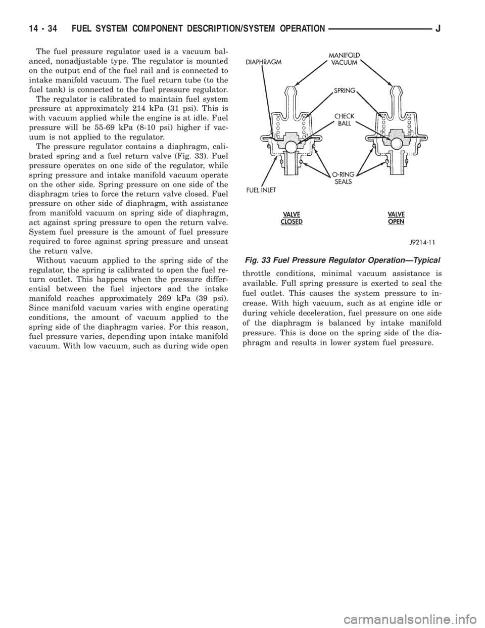
The pressure regulator contains a diaphragm, cali-
brated spring and a fuel return valve (Fig. 33). Fuel
pressure operates on one side of the regulator, while
spring pressure and intake manifold vacuum operate
on the other side. Spring pressure on one side of the
diaphragm tries to force the return valve closed. Fuel
pressure on other side of diaphragm, with assistance
from manifold vacuum on spring side of diaphragm,
act against spring pressure to open the return valve.
System fuel pressure is the amount of fuel pressure
required to force against spring pressure and unseat
the return valve.
Without vacuum applied to the spring side of the
regulator, the spring is calibrated to open the fuel re-
turn outlet. This happens when the pressure differ-
ential between the fuel injectors and the intake
manifold reaches approximately 269 kPa (39 psi).
Since manifold vacuum varies with engine operating
conditions, the amount of vacuum applied to the
spring side of the diaphragm varies. For this reason,
fuel pressure varies, depending upon intake manifold
vacuum. With low vacuum, such as during wide openthrottle conditions, minimal vacuum assistance is
available. Full spring pressure is exerted to seal the
fuel outlet. This causes the system pressure to in-
crease. With high vacuum, such as at engine idle or
during vehicle deceleration, fuel pressure on one side
of the diaphragm is balanced by intake manifold
pressure. This is done on the spring side of the dia-
phragm and results in lower system fuel pressure.
Fig. 33 Fuel Pressure Regulator OperationÐTypical
14 - 34 FUEL SYSTEM COMPONENT DESCRIPTION/SYSTEM OPERATIONJ
Page 1274 of 2198
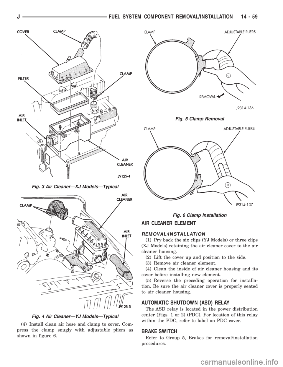
(4) Install clean air hose and clamp to cover. Com-
press the clamp snugly with adjustable pliers as
shown in figure 6.
AIR CLEANER ELEMENT
REMOVAL/INSTALLATION
(1) Pry back the six clips (YJ Models) or three clips
(XJ Models) retaining the air cleaner cover to the air
cleaner housing.
(2) Lift the cover up and position to the side.
(3) Remove air cleaner element.
(4) Clean the inside of air cleaner housing and its
cover before installing new element.
(5) Reverse the preceding operation for installa-
tion. Be sure the air cleaner cover is properly seated
to air cleaner housing.
AUTOMATIC SHUTDOWN (ASD) RELAY
The ASD relay is located in the power distribution
center (Figs. 1 or 2) (PDC). For location of this relay
within the PDC, refer to label on PDC cover.
BRAKE SWITCH
Refer to Group 5, Brakes for removal/installation
procedures.
Fig. 3 Air CleanerÐXJ ModelsÐTypical
Fig. 4 Air CleanerÐYJ ModelsÐTypical
Fig. 5 Clamp Removal
Fig. 6 Clamp Installation
JFUEL SYSTEM COMPONENT REMOVAL/INSTALLATION 14 - 59
Page 1277 of 2198
FUEL RAIL ASSEMBLY
REMOVAL
WARNING: THE FUEL SYSTEM IS UNDER CON-
STANT FUEL PRESSURE (EVEN WITH THE ENGINE
OFF) OF APPROXIMATELY 131-269 KPA (19-39 PSI).
THIS PRESSURE MUST BE RELEASED BEFORE
SERVICING THE FUEL RAIL.
(1) Remove fuel tank filler tube cap.
(2) Disconnect the negative battery cable from bat-
tery.
(3) Perform the Fuel System Pressure Release Pro-
cedure as described in the Fuel Delivery System sec-
tion of this Group.
(4) Remove and numerically attach a tag (if fuel
injector is not already tagged), the injector harness
connectors. Do this at each injector (Fig. 12).
(5) Disconnect vacuum line from fuel pressure reg-
ulator (Fig. 12).
(6) Disconnect fuel supply line from fuel rail and
the fuel return line from fuel pressure regulator (Fig.
12). Refer to Fuel Tubes/Lines/Hoses and Clamps, or
Quick-Connect Fittings. These can both be found in
the Fuel Delivery section of this group.
(7) Remove fuel rail mounting bolts.
On models with automatic transmissions, it may be
necessary to remove automatic transmission throttle
line pressure cable and bracket. This will aid in fuel
rail assembly removal.
(8) Remove fuel rail by gently rocking until all the
fuel injectors are out of the intake manifold.
INSTALLATION
(1) Position tips of all fuel injectors into the corre-
sponding injector bore in the intake manifold. Seat
injectors into manifold.
(2) Tighten fuel rail mounting bolts to 27 Nzm (20
ft. lbs.) torque.
(3) Connect injector harness connectors to appro-
priate (tagged) injector.
(4) Connect both fuel lines to fuel rail. Refer to the
Fuel Delivery section of this group for procedures.
(5) Connect vacuum supply line to fuel pressure
regulator.
(6) Install protective cap to pressure test port fit-
ting.
(7) Install fuel tank cap.
(8) Connect negative battery cable to battery.
(9) Start engine and check for fuel leaks.
FUEL SYSTEM PRESSURE RELEASE PROCEDURE
WARNING: THE FUEL SYSTEM IS UNDER A CON-
STANT PRESSURE (EVEN WITH THE ENGINE OFF)
OF APPROXIMATELY 100 KPA (14.5 PSI). BEFORE
SERVICING THE FUEL PUMP, FUEL RAIL, FUELLINES, FUEL FILTER OR FUEL INJECTOR, THE
FUEL SYSTEM PRESSURE MUST BE RELEASED.
Refer to the Fuel Delivery System section of this
group. See Fuel Pressure Release procedure.
FUEL TANKS
Refer to the Fuel Tank section of this group for re-
moval/installation procedures.
FUEL TANK PRESSURE RELIEF/ROLLOVER VALVE
Refer to the Fuel Tank section of this group for re-
moval/installation procedures.
FUEL TUBES/LINES/HOSES AND CLAMPS
Refer to the Fuel Delivery System section of this
group for removal/installation procedures. Also refer
to Quick-Connect Fittings in the Fuel Delivery sec-
tion of this group.
IDLE AIR CONTROL (IAC) MOTOR
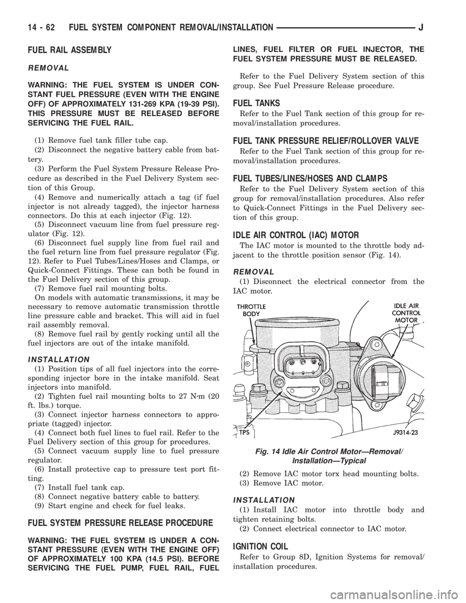
The IAC motor is mounted to the throttle body ad-
jacent to the throttle position sensor (Fig. 14).
REMOVAL
(1) Disconnect the electrical connector from the
IAC motor.
(2) Remove IAC motor torx head mounting bolts.
(3) Remove IAC motor.
INSTALLATION
(1) Install IAC motor into throttle body and
tighten retaining bolts.
(2) Connect electrical connector to IAC motor.
IGNITION COIL
Refer to Group 8D, Ignition Systems for removal/
installation procedures.
Fig. 14 Idle Air Control MotorÐRemoval/
InstallationÐTypical
14 - 62 FUEL SYSTEM COMPONENT REMOVAL/INSTALLATIONJ
Page 1282 of 2198
speedometer pinion gear adapter (Fig. 29). Do not re-
move the gear adapter from the transmission.
INSTALLATION
(1) Clean the inside of speedometer pinion gear
adapter before installing speed sensor.
(2) Install sensor into speedometer gear adapter
and install mounting bolt.Before tightening bolt,verify speed sensor is fully seated (mounted
flush) to speedometer pinion gear adapter.
(3) Tighten sensor mounting bolt to 2.2 Nzm (20 in.
lbs.) torque.
(4) Connect electrical connector to sensor.
SPECIFICATIONS
GENERAL INFORMATION
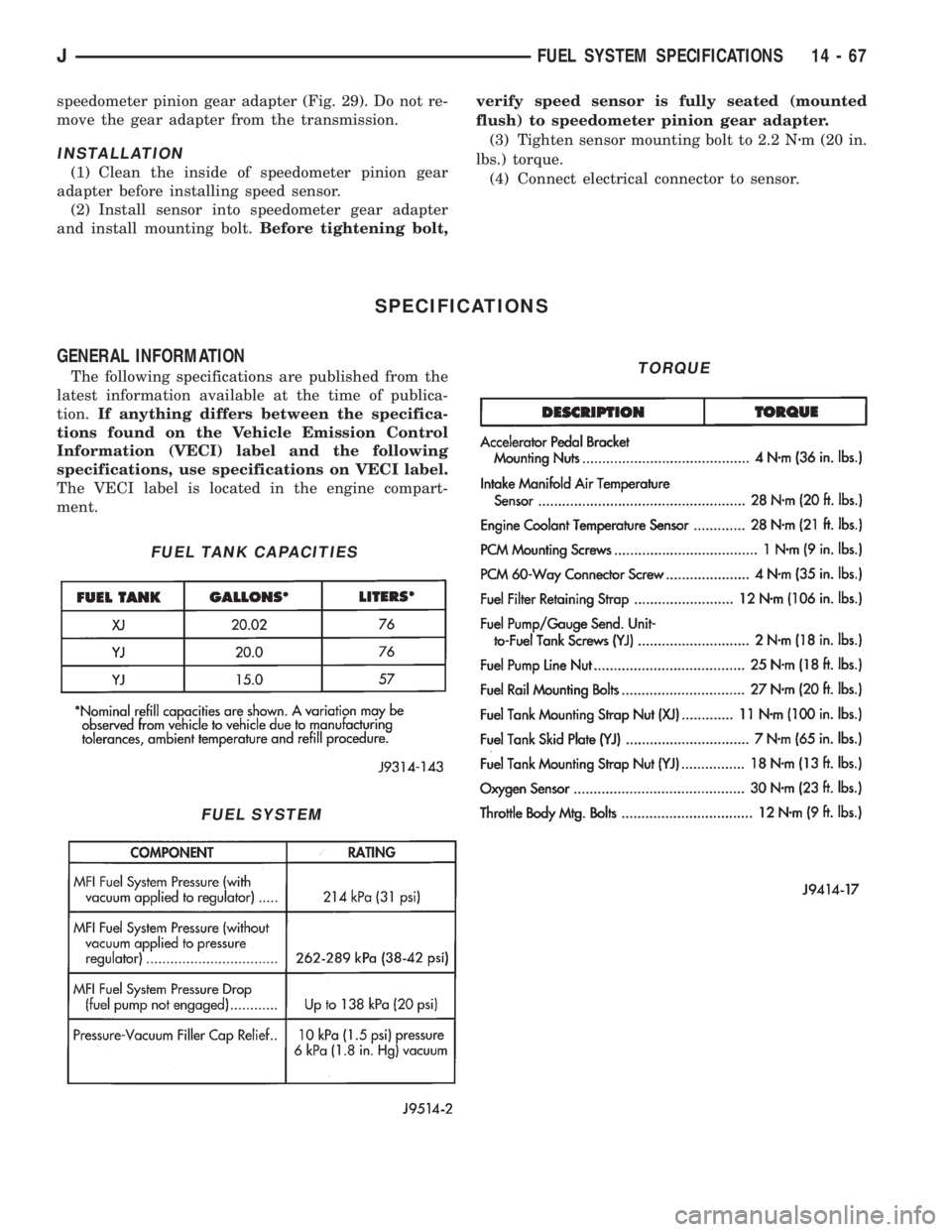
The following specifications are published from the
latest information available at the time of publica-
tion.If anything differs between the specifica-
tions found on the Vehicle Emission Control
Information (VECI) label and the following
specifications, use specifications on VECI label.
The VECI label is located in the engine compart-
ment.
FUEL TANK CAPACITIES
FUEL SYSTEM
TORQUE
JFUEL SYSTEM SPECIFICATIONS 14 - 67
Page 1294 of 2198
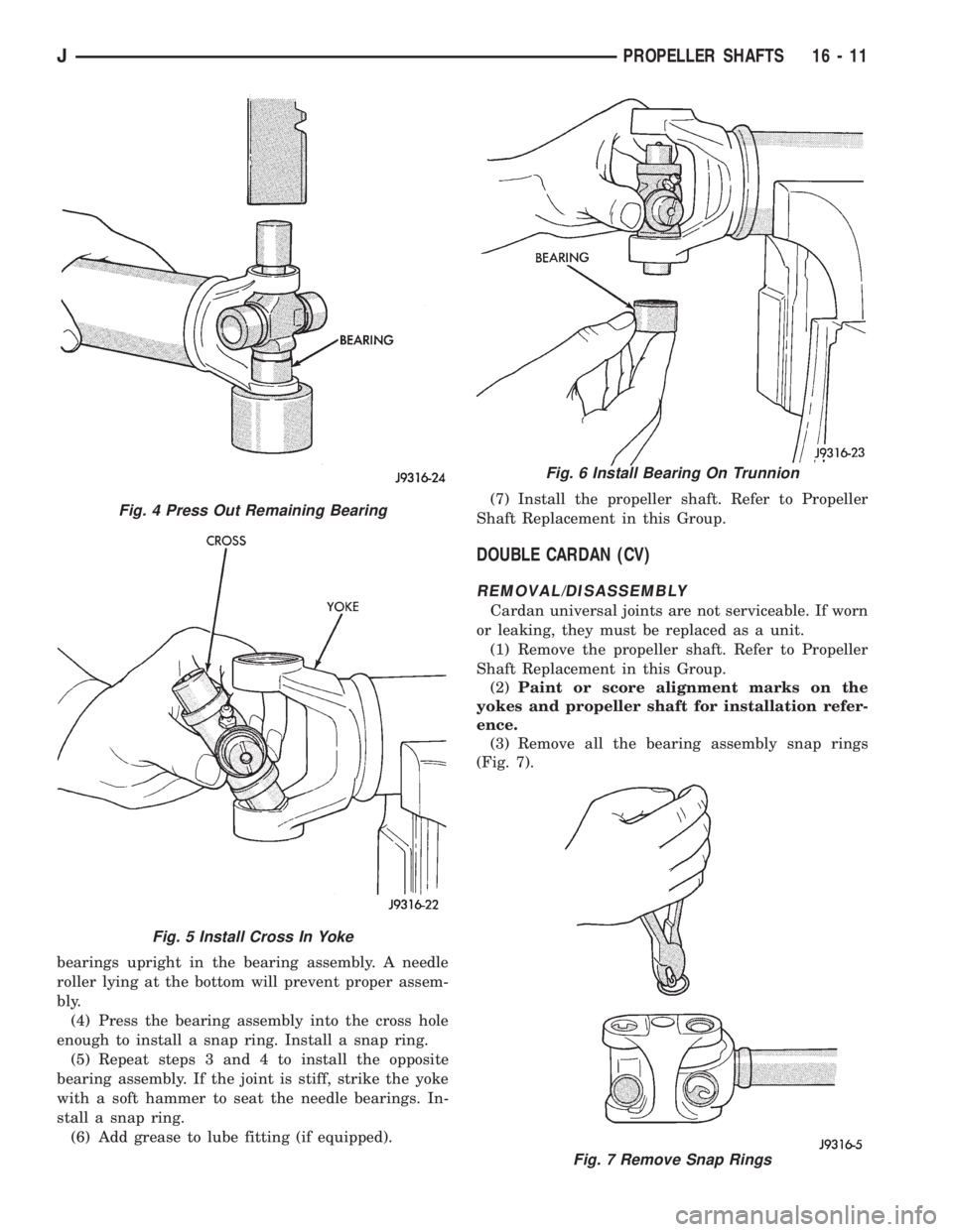
bearings upright in the bearing assembly. A needle
roller lying at the bottom will prevent proper assem-
bly.
(4) Press the bearing assembly into the cross hole
enough to install a snap ring. Install a snap ring.
(5) Repeat steps 3 and 4 to install the opposite
bearing assembly. If the joint is stiff, strike the yoke
with a soft hammer to seat the needle bearings. In-
stall a snap ring.
(6) Add grease to lube fitting (if equipped).(7) Install the propeller shaft. Refer to Propeller
Shaft Replacement in this Group.
DOUBLE CARDAN (CV)
REMOVAL/DISASSEMBLY
Cardan universal joints are not serviceable. If worn
or leaking, they must be replaced as a unit.
(1) Remove the propeller shaft. Refer to Propeller
Shaft Replacement in this Group.
(2)Paint or score alignment marks on the
yokes and propeller shaft for installation refer-
ence.
(3) Remove all the bearing assembly snap rings
(Fig. 7).
Fig. 4 Press Out Remaining Bearing
Fig. 5 Install Cross In Yoke
Fig. 6 Install Bearing On Trunnion
Fig. 7 Remove Snap Rings
JPROPELLER SHAFTS 16 - 11
Page 1297 of 2198
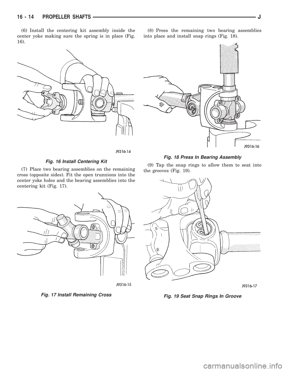
(6) Install the centering kit assembly inside the
center yoke making sure the spring is in place (Fig.
16).
(7) Place two bearing assemblies on the remaining
cross (opposite sides). Fit the open trunnions into the
center yoke holes and the bearing assemblies into the
centering kit (Fig. 17).(8) Press the remaining two bearing assemblies
into place and install snap rings (Fig. 18).
(9) Tap the snap rings to allow them to seat into
the grooves (Fig. 19).
Fig. 16 Install Centering Kit
Fig. 17 Install Remaining Cross
Fig. 18 Press In Bearing Assembly
Fig. 19 Seat Snap Rings In Groove
16 - 14 PROPELLER SHAFTSJ
Page 1327 of 2198
PITMAN SHAFT AND SIDE COVER REPLACEMENT
REMOVE
(1) Remove steering gear from vehicle. Refer to
Power Steering Gear Replacement in this section.
(2) Remove pitman arm from steering gear. Refer
to Pitman Arm Removal in the Steering Linkage sec-
tion.
(3) Rotate stub shaft back and forth to drain power
steering fluid.
DISASSEMBLE
²Clean exposed end of pitman shaft and housing.
²Clean pitman shaft spline with a wire brush.
(1) Remove preload adjuster nut.
(2) Rotate stub shaft with socket to center gear.
Remove side cover bolts.
(3) Remove side cover, gasket and pitman shaft as
an assembly.
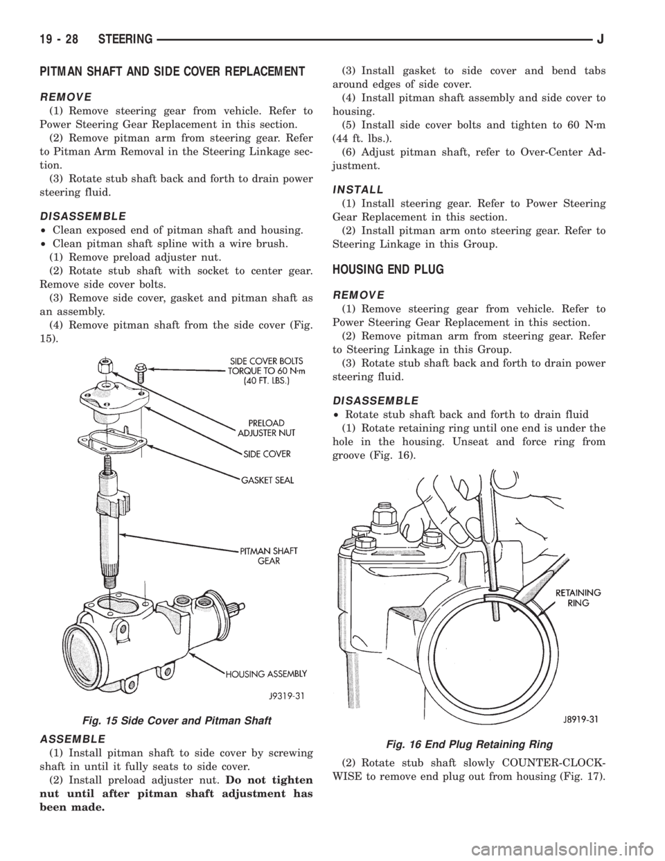
(4) Remove pitman shaft from the side cover (Fig.
15).
ASSEMBLE
(1) Install pitman shaft to side cover by screwing
shaft in until it fully seats to side cover.
(2) Install preload adjuster nut.Do not tighten
nut until after pitman shaft adjustment has
been made.(3) Install gasket to side cover and bend tabs
around edges of side cover.
(4) Install pitman shaft assembly and side cover to
housing.
(5) Install side cover bolts and tighten to 60 Nzm
(44 ft. lbs.).
(6) Adjust pitman shaft, refer to Over-Center Ad-
justment.
INSTALL
(1) Install steering gear. Refer to Power Steering
Gear Replacement in this section.
(2) Install pitman arm onto steering gear. Refer to
Steering Linkage in this Group.
HOUSING END PLUG
REMOVE
(1) Remove steering gear from vehicle. Refer to
Power Steering Gear Replacement in this section.
(2) Remove pitman arm from steering gear. Refer
to Steering Linkage in this Group.
(3) Rotate stub shaft back and forth to drain power
steering fluid.
DISASSEMBLE
²Rotate stub shaft back and forth to drain fluid
(1) Rotate retaining ring until one end is under the
hole in the housing. Unseat and force ring from
groove (Fig. 16).
(2) Rotate stub shaft slowly COUNTER-CLOCK-
WISE to remove end plug out from housing (Fig. 17).
Fig. 15 Side Cover and Pitman Shaft
Fig. 16 End Plug Retaining Ring
19 - 28 STEERINGJ
Page 1328 of 2198
CAUTION: Do not turn stub shaft any farther than
necessary. The recirculating balls will drop out of
the rack piston circuit and fall inside the rack pis-
ton chamber.
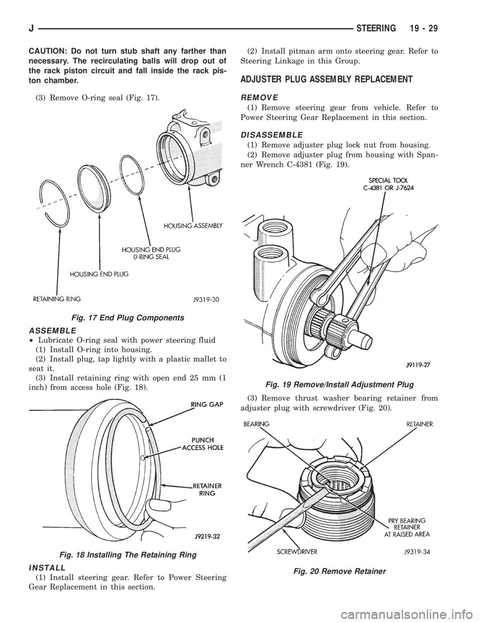
(3) Remove O-ring seal (Fig. 17).
ASSEMBLE
²Lubricate O-ring seal with power steering fluid
(1) Install O-ring into housing.
(2) Install plug, tap lightly with a plastic mallet to
seat it.
(3) Install retaining ring with open end 25 mm (1
inch) from access hole (Fig. 18).
INSTALL
(1) Install steering gear. Refer to Power Steering
Gear Replacement in this section.(2) Install pitman arm onto steering gear. Refer to
Steering Linkage in this Group.
ADJUSTER PLUG ASSEMBLY REPLACEMENT
REMOVE
(1) Remove steering gear from vehicle. Refer to
Power Steering Gear Replacement in this section.
DISASSEMBLE
(1) Remove adjuster plug lock nut from housing.
(2) Remove adjuster plug from housing with Span-
ner Wrench C-4381 (Fig. 19).
(3) Remove thrust washer bearing retainer from
adjuster plug with screwdriver (Fig. 20).
Fig. 17 End Plug Components
Fig. 18 Installing The Retaining Ring
Fig. 19 Remove/Install Adjustment Plug
Fig. 20 Remove Retainer
JSTEERING 19 - 29