1995 JEEP CHEROKEE anti seize
[x] Cancel search: anti seizePage 143 of 2198

pedal. The proper course of action is to bleed the sys-
tem, or replace thin drums and suspect quality brake
lines and hoses.
HARD PEDAL OR HIGH PEDAL EFFORT
A hard pedal or high pedal effort may be due to lin-
ing that is water soaked, contaminated, glazed, or
badly worn. The power booster or check valve could
also be faulty. Test the booster and valve as described
in this section.
BRAKE DRAG
Brake drag occurs when the lining is in constant
contact with the rotor or drum. Drag can occur at one
wheel, all wheels, fronts only, or rears only. It is a
product of incomplete brakeshoe release. Drag can be
minor or severe enough to overheat the linings, ro-
tors and drums. A drag condition also worsens as
temperature of the brake parts increases.
Brake drag also has a direct effect on fuel economy.
If undetected, minor brake drag can be misdiagnosed
as an engine or transmission/torque converter prob-
lem.
Minor drag will usually cause slight surface char-
ring of the lining. It can also generate hard spots in
rotors and drums from the overheat/cool down pro-
cess. In most cases, the rotors, drums, wheels and
tires are quite warm to the touch after the vehicle is
stopped.
Severe drag can char the brake lining all the way
through. It can also distort and score rotors and
drums to the point of replacement. The wheels, tires
and brake components will be extremely hot. In se-
vere cases, the lining may generate smoke as it chars
from overheating.
An additional cause of drag involves the use of in-
correct length caliper mounting bolts. Bolts that are
too long can cause a partial apply condition. The cor-
rect caliper bolts have a shank length of 67 mm
(2.637 in.), plus or minus 0.6 mm (0.0236 in.). Refer
to the Disc Brake service section for more detail on
caliper bolt dimensions and identification.
Some common causes of brake drag are:
²loose or damaged wheel bearing
²seized or sticking caliper or wheel cylinder piston
²caliper binding on bolts or slide surfaces
²wrong length caliper mounting bolts (too long)
²loose caliper mounting bracket
²distorted rotor, brake drum, or shoes
²brakeshoes binding on worn/damaged support
plates
²severely rusted/corroded components
²misassembled components.
If brake drag occurs at all wheels, the problem may
be related to a blocked master cylinder compensatorport or faulty power booster (binds-does not release).
The condition will worsen as brake temperature in-
creases.
The brakelight switch can also be a cause of drag.
An improperly mounted or adjusted brakelight
switch can prevent full brake pedal return. The re-
sult will be the same as if the master cylinder com-
pensator ports are blocked. The brakes would be
partially applied causing drag.
BRAKE FADE
Brake fade is a product of overheating caused by
brake drag. However, overheating and subsequent
fade can also be caused by riding the brake pedal,
making repeated high deceleration stops in a short
time span, or constant braking on steep roads. Refer
to the Brake Drag information in this section for
causes.
PEDAL PULSATION (NON-ABS BRAKES ONLY)
Pedal pulsation is caused by parts that are loose,
or beyond tolerance limits. This type of pulsation is
constant and will occur every time the brakes are ap-
plied.
Disc brake rotors with excessive lateral runout or
thickness variation, or out of round brake drums are
the primary causes of pulsation.
On vehicles with ABS brakes, remember that pedal
pulsation is normal during antilock mode brake
stops. If pulsation occurs during light to moderate
brake stops, a standard brake part is either loose, or
worn beyond tolerance.
BRAKE PULL
A front pull condition could be the result of:
²contaminated lining in one caliper
²seized caliper piston
²binding caliper
²wrong caliper mounting bolts (too long)
²loose caliper
²loose or corroded mounting bolts
²improper brakeshoes
²damaged rotor
²incorrect wheel bearing adjustment (at one wheel)
A worn, damaged wheel bearing or suspension com-
ponent are further causes of pull. A damaged front
tire (bruised, ply separation) can also cause pull.
Wrong caliper bolts (too long) will cause a partial ap-
ply condition and pull if only one caliper is involved.
A common and frequently misdiagnosed pull condi-
tion is where direction of pull changes after a few
stops. The cause is a combination of brake drag fol-
lowed by fade at the dragging brake unit.
As the dragging brake overheats, efficiency is so re-
duced that fade occurs. If the opposite brake unit is
still functioning normally, its braking effect is magni-
5 - 6 SERVICE BRAKE DIAGNOSISJ
Page 1191 of 2198

INSTALLATION
(1) Assemble exhaust pipe to manifold and cata-
lytic converter loosely to permit proper alignment of
all parts.
(2) Use a new clamp and tighten the nuts to 61
Nzm (45 ft. lbs.) torque.
(3) Connect the exhaust pipe to the engine exhaust
manifold. Install a new seal between the exhaust
manifold and the exhaust pipe (4.0L engine, only).
Tighten the nuts to 31 Nzm (23 ft. lbs.) torque (Fig.
1).
(3) Install the rear crossmember. Tighten the
crossmember-to-sill bolts to 41 Nzm (30 ft. lbs.)
torque. Remove the support from the transmission.
(4) Coat the oxygen sensor with anti-seize com-
pound. Install the sensor and tighten the nut to 48
Nzm (35 ft. lbs.) torque.
(5) Lower the vehicle.
(6) Start the engine and inspect for exhaust leaks
and exhaust system contact with the body panels.
Adjust the alignment, if needed.
EXHAUST PIPEÐYJ VEHICLES
WARNING: IF TORCHES ARE USED WHEN WORK-
ING ON THE EXHAUST SYSTEM, DO NOT ALLOW
THE FLAME NEAR THE FUEL LINES.
REMOVAL
(1) Raise and support the vehicle.
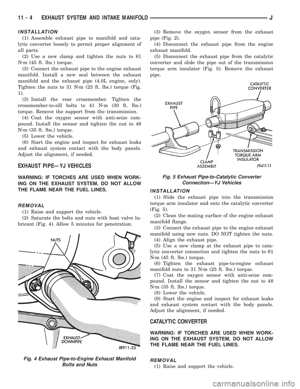
(2) Saturate the bolts and nuts with heat valve lu-
bricant (Fig. 4). Allow 5 minutes for penetration.(3) Remove the oxygen sensor from the exhaust
pipe (Fig. 2).
(4) Disconnect the exhaust pipe from the engine
exhaust manifold.
(5) Disconnect the exhaust pipe from the catalytic
converter and slide the pipe out of the transmission
torque arm insulator (Fig. 5). Remove the exhaust
pipe.
INSTALLATION
(1) Slide the exhaust pipe into the transmission
torque arm insulator and onto the catalytic converter
(Fig. 5).
(2) Clean the mating surface of the engine exhaust
manifold flange.
(3) Connect the exhaust pipe to the engine exhaust
manifold using new nuts. DO NOT tighten the nuts.
(4) Align the exhaust pipe.
(5) Use a new clamp at the exhaust pipe to cata-
lytic converter connection and tighten the nuts to 61
Nzm (45 ft. lbs.) torque.
(6) Tighten the exhaust pipe-to-engine exhaust
manifold nuts to 31 Nzm (23 ft. lbs.) torque.
(7) Coat the oxygen sensor with anti-seize com-
pound. Install the sensor and tighten the nut to 48
Nzm (35 ft. lbs.) torque.
(8) Lower the vehicle.
(9) Start the engine and inspect for exhaust leaks
and exhaust system contact with the body panels.
Adjust the alignment, if needed.
CATALYTIC CONVERTER
WARNING: IF TORCHES ARE USED WHEN WORK-
ING ON THE EXHAUST SYSTEM, DO NOT ALLOW
THE FLAME NEAR THE FUEL LINES.
REMOVAL
(1) Raise and support the vehicle.
Fig. 4 Exhaust Pipe-to-Engine Exhaust Manifold
Bolts and Nuts
Fig. 5 Exhaust Pipe-to-Catalytic Converter
ConnectionÐYJ Vehicles
11 - 4 EXHAUST SYSTEM AND INTAKE MANIFOLDJ
Page 1278 of 2198

INTAKE MANIFOLD
Refer to Group 11, Exhaust System and Intake
Manifold for removal/installation procedures.
MANIFOLD ABSOLUTE PRESSURE (MAP) SENSOR
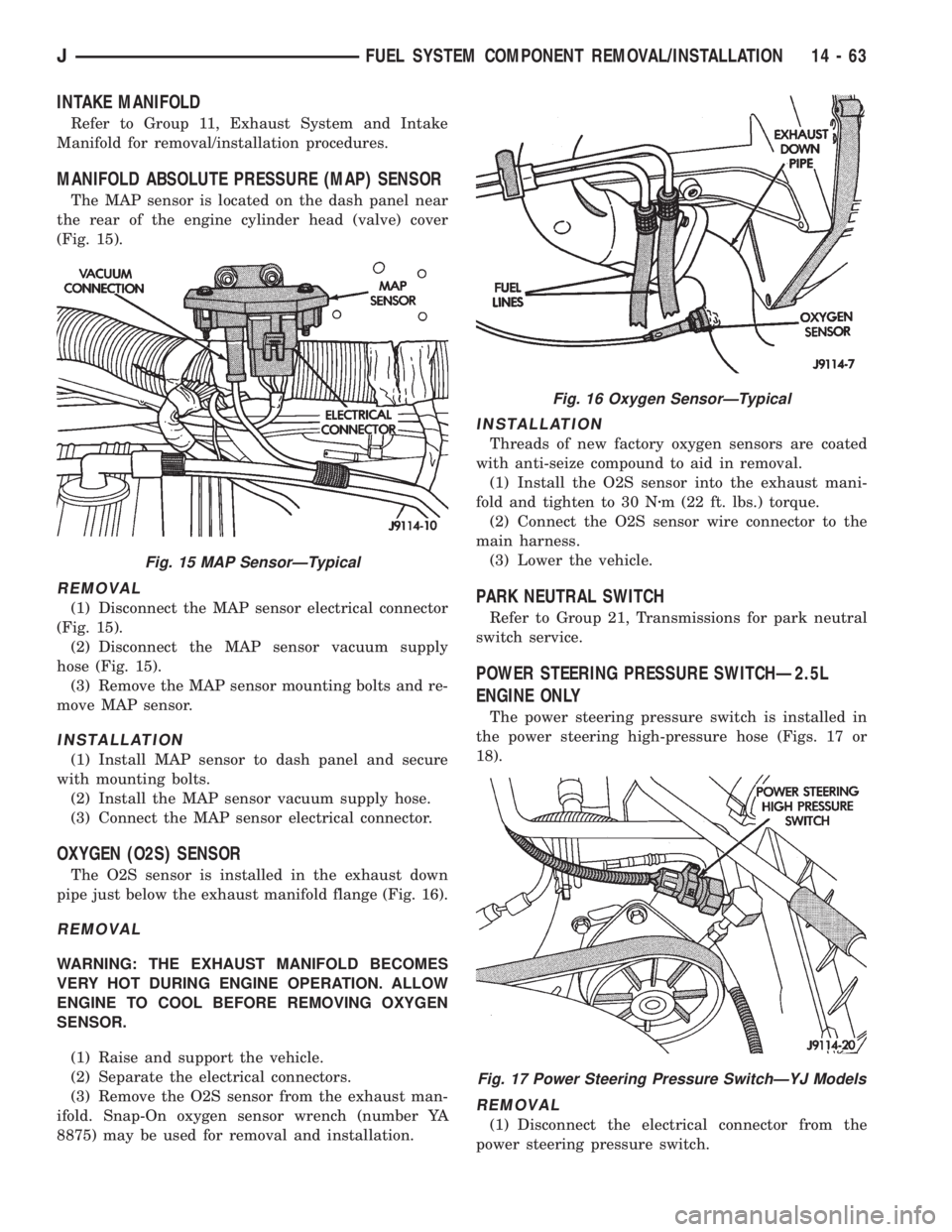
The MAP sensor is located on the dash panel near
the rear of the engine cylinder head (valve) cover
(Fig. 15).
REMOVAL
(1) Disconnect the MAP sensor electrical connector
(Fig. 15).
(2) Disconnect the MAP sensor vacuum supply
hose (Fig. 15).
(3) Remove the MAP sensor mounting bolts and re-
move MAP sensor.
INSTALLATION
(1) Install MAP sensor to dash panel and secure
with mounting bolts.
(2) Install the MAP sensor vacuum supply hose.
(3) Connect the MAP sensor electrical connector.
OXYGEN (O2S) SENSOR
The O2S sensor is installed in the exhaust down
pipe just below the exhaust manifold flange (Fig. 16).
REMOVAL
WARNING: THE EXHAUST MANIFOLD BECOMES
VERY HOT DURING ENGINE OPERATION. ALLOW
ENGINE TO COOL BEFORE REMOVING OXYGEN
SENSOR.
(1) Raise and support the vehicle.
(2) Separate the electrical connectors.
(3) Remove the O2S sensor from the exhaust man-
ifold. Snap-On oxygen sensor wrench (number YA
8875) may be used for removal and installation.
INSTALLATION
Threads of new factory oxygen sensors are coated
with anti-seize compound to aid in removal.
(1) Install the O2S sensor into the exhaust mani-
fold and tighten to 30 Nzm (22 ft. lbs.) torque.
(2) Connect the O2S sensor wire connector to the
main harness.
(3) Lower the vehicle.
PARK NEUTRAL SWITCH
Refer to Group 21, Transmissions for park neutral
switch service.
POWER STEERING PRESSURE SWITCHÐ2.5L
ENGINE ONLY
The power steering pressure switch is installed in
the power steering high-pressure hose (Figs. 17 or
18).
REMOVAL
(1) Disconnect the electrical connector from the
power steering pressure switch.
Fig. 15 MAP SensorÐTypical
Fig. 16 Oxygen SensorÐTypical
Fig. 17 Power Steering Pressure SwitchÐYJ Models
JFUEL SYSTEM COMPONENT REMOVAL/INSTALLATION 14 - 63