1995 JEEP CHEROKEE seat
[x] Cancel search: seatPage 633 of 2198
READING LAMPS
Circuit M1 from the IOD fuse (fuse F9) in the fuse
block supplies power to the reading lamps. Circuit
M1 is HOT at all times. When the operator depresses
the reading lamp, the reading lamp switch closes and
supplies ground on circuit Z1.
VISOR VANITY MIRROR LAMPS
Circuit M1 from the IOD fuse (fuse F9) in the fuse
block supplies power to the vanity lamps. Circuit M1
is HOT at all times. When the vanity lamps switch
closes, voltage flows to vanity mirror lamps. The van-
ity mirror is case grounded.
UNDERHOOD LAMP
Circuit A6 from fuse 16 in the Power Distribution
Center (PDC) supplies battery voltage for the under-
hood lamp. A mercury switch, in series after the
lamp, connects the lamp to ground on circuit Z1.
When the hood is raised, mercury inside the switch
moves to a position where it connects circuit M1 to
ground circuit Z1, illuminating the lamp.
CHIME/BUZZER MODULE
The buzzer or optional chime module sounds an au-
dible warning tone. The tone sounds for seat belt
warning and when the ignition key is in the ignition
switch while the drivers door is open. The tone also
sounds when the ignition key is in the ON position
while the drivers side seat belt is not buckled. Lastly,
the tone sounds when the headlamps are ON when
the ignition is OFF. Refer to Group 8U for system op-
eration.
When the ignition switch is in the RUN or START
position, circuit F87 from fuse 17 in the fuse block
supplies power to the chime/buzzer module. Circuit
A21 from the ignition switch supplies power to fuse
17.
Circuit L7 from fuse 15 in the fuse block also sup-
plies power to the chime/buzzer module. Circuit A3
from fuse 5 in the Power Distribution Center (PDC)
powers fuse 15.
When the parking lamps or headlamps are ON, the
headlamp switch connects circuit G26 with the driv-
ers side door jamb switch. Circuit G26 also connects
to the key-in switch. Circuit M11 connects the key-in
switch to the chime/buzzer module and the headlamp
switch.
If the headlamps are ON, and the drivers door
opens, ground for the chime/buzzer is on circuit C26
from the headlamp switch through the door jamb
switch to circuit Z1.
If the headlamps are OFF with the key in the ig-
nition while the drivers side door is open, ground forthe chime/buzzer is supplied through the key-in
switch. The ground path is over circuit M11, through
the closed key-in switch to circuit C26. From circuit
C26, the ground path continues through the drivers
door jamb switch to circuit Z1.
Circuit G11 from the buzzer powers the seat belt
warning lamp in the instrument cluster. Circuit Z1
at the instrument cluster provides ground for the
lamp.
Circuit G10 from the buzzer connects to the seat
belt switch. When the seat belt switch closes a path
to ground is completed on circuit Z1 and the tone
sounds momentarily.
Circuit Z1 also grounds the chime\buzzer module.
HELPFUL INFORMATION
Circuit F87 also powers the instrument cluster and
the headlamp delay module.
DIAGRAM INDEX
Component Page
Cargo Lamp............................8W-44-6
Chime/Buzzer Module......................8W-44-3
Courtesy Lamps.........................8W-44-5
Dome Lamp............................8W-44-7
Door Jamb Switches.....................8W-44-10
Fuse 3 (PDC).........................8W-44-4, 6
Fuse 5 (PDC).........................8W-44-3, 8
Fuse 6 (PDC)...........................8W-44-3
Fuse 9 (Fuse Block).....................8W-44-4, 6
Fuse 15 (Fuse Block)....................8W-44-3, 8
Fuse 16 (PDC)........................8W-44-4, 6
Fuse 17 (Fuse Block)......................8W-44-3
Fuse 19 (Fuse Block)......................8W-44-8
Glove Box Lamp and Switch.................8W-44-5
Headlamp Switch...................8W-44-3, 4, 5, 8
Headlamp Delay Module....................8W-44-4
Headlamp Delay Relay.....................8W-44-3
Ignition Switch..........................8W-44-3
Instrument Cluster........................8W-44-3
Instrument Panel Illumination Lamps..........8W-44-8, 9
Intermittent Wiper Control Module.............8W-44-4
Key-In Switch...........................8W-44-4
Liftgate Switch..........................8W-44-6
Reading Lamps..........................8W-44-7
Remote Keyless Entry Module................8W-44-7
Seat Belt Switch.........................8W-44-3
Telltale Connector (Instrument Cluster)...........8W-44-3
Time Delay Relay........................8W-44-4
Underhood Lamp.........................8W-44-4
Vanity Lamps...........................8W-44-7
8W - 44 - 2 8W-44 INTERIOR LIGHTINGÐXJ VEHICLESJ
Page 702 of 2198
POWER SEAT
POWER SEAT
Battery voltage for the power seat system is sup-
plied by circuit A11, which is HOT at all times. This
circuit connects to the power accessory tap in the
fuse block and the power seat switch. The circuit
breaker in cavity 16 protects circuit A11.
A BUS bar internal to the power seat switch con-
nects the power from circuit A11 to the switches.
Grounding for the seat system is supplied on circuit
Z1.
The motors located under the seat are protected by
circuit breakers wired in with the motors. Each mo-
tor has its own circuit breaker.
When the operator selects the FRONT VERTICAL
UP function, power is passed on the A11 circuit
through the closed contacts in the switch to the S5
circuit. The S5 circuit connects to the motor. Ground
is provided on the S6 circuit back to the switch. A
ground BUS bar internal to the switch then connects
to the Z1 circuit.
For FRONT VERTICAL DOWN function the cir-
cuits are reversed. S6 is the feed and S5 is the
ground.
When the operator selects the SEAT FORWARD
function, power is passed on the A11 circuit through
the closed contacts in the switch to the S3 circuit.
The S3 circuit connects to the motor. Ground is pro-
vided on the S4 circuit back to the switch. A ground
BUS bar internal to the switch then connects to the
Z1 circuit.
For SEAT REARWARD function the circuits are re-
versed. S4 is the feed and S3 is the ground.
When the operator selects the REAR VERTICAL
UP function, power is passed on the A11 circuitthrough the closed contacts in the switch to the S1
circuit. The S1 circuit connects to the motor. Ground
is provided on the S2 circuit back to the switch. A
ground BUS bar internal to the switch then connects
to the Z1 circuit.
For REAR VERTICAL DOWN function the circuits
are reversed. S2 is the feed and S1 is the ground.
When the operator selects the SEAT UP function
power is passed on the A11 circuit through the closed
contacts in the switch to the S1 and S5 circuits. The
S1 circuit connects to the rear UP/DOWN motor, and
S5 connects to the front UP/DOWN motor. Ground is
provided on the S2 and S6 circuits back to the
switch. A ground BUS bar internal to the switch then
connects to the Z1 circuit.
For SEAT DOWN function the circuits are re-
versed. S2 and S6 circuits are the feeds and S1 and
S5 are the grounds.
HELPFUL INFORMATION
²Check the 30 amp circuit breaker in cavity 16 of
the fuse block.
DIAGRAM INDEX
Component Page
Circuit Breaker (Fuse Block Cavity 16)...........8W-63-2
Fuse 3 (Fuse Block).......................8W-63-2
Power Seat............................8W-63-2
Power Seat Switch.......................8W-63-2
J8W-63 POWER SEATÐXJ VEHICLES 8W - 63 - 1
Page 781 of 2198
Connector # Color Location Fig.
C226......BK ...Left Kick Panel
C227......BK ...OnI.P.Right of Steering Column . . .10
C228......BK ...Left Side of Steering Column.....14
C229......BK ...TopofBrake Pedal Arm.........13
C230......BK ...Left Side of I.P...............12
C231......BK ...Center of I.P.................10
C232......GY ...Left Side of I.P...............12
C233......BK ...Left Side of I.P...............12
C234......BK ...Rear of I.P. Cluster............10
C235......NAT...Rear of I.P. Cluster............10
C236......BK ...OnI.P.Right of Steering Column . . .10
C237......BK ...OnI.P.Right of Steering Column . . .10
C238......BK ...OnI.P.Left of Steering Column....10
C239......RD ...OnI.P.Left of Steering Column....10
C240......BK ...Left Front Door..............17
C241......BK ...Center of I.P.
C242......BK ...Center Bottom of I.P..........9,11
C243......BK ...Center Left of I.P.
C301......DG ...Behind Left Kick Panel
C302......BK ...Near Floor Console
C303......BK ...Bottom Right of Drivers Seat . . .15, 23
C304......BK ...Bottom of Drivers Sear.........15
C305......BK ...Behind Right Kick Panel........17
C306......BK ...Left B Pillar................18
C307......BK ...Near Fuel Tank..............15
C308......BK ...InLiftgate.................24
C309......BK ...Under Rear of Roof Liner........20
C310......BK ...Left Rear Quarter Panel.........20
C311......BK ...Left Rear Quarter Panel.........20
C312......BK ...Left Rear Quarter Panel.........20
C313......BK ...InLiftgate.................24
C314......NAT...InLeft Rear Door.............18
C315......BK ...InLeft Rear Door.............18
C316......RD ...InLeft Rear Door.............18
C317......BK ...Behind Left Kick Panel.......15, 17
C318......RD ...Behind Left Kick Panel.......15, 17
C319......BK ...Under Floor Console...........15
C320......GY ...Under Right Rear Seat.........18
C321......BK ...Behind Right Kick Panel........17
C322......DG ...AtDome Lamp
C323......BK ...InLiftgate.................24
C324......BK ...Right Rear Quarter Panel........20
C325......NAT...InRight Rear Door............18
C326......BK ...InRight Rear Door............18
C327......BK ...InRight Rear Door............18
C328......BK ...InRight B Pillar..............18
C329......BK ...InRight Front Door...........17
C331......BK ...InRight Front Door...........17
C332......BK ...InRight Front Door...........17
C333......BK ...InRight Front Door...........17
C334......BK ...InRight Front Door...........17
C335......BK ...InLeft Front Door............17
C336......BK ...InLeft Front Door............17
C338......BK ...InLeft Front Door............17
C339......BK ...InLeft Front Door............17
C340......BK ...InLeft Front Door............17
C341......BK ...InLeft Front Door............17Connector # Color Location Fig.
C342......BK ...Front Center of Roof Liner.......16
C343......BK ...Behind Overhead Console.......16
C344......BK ...Behind Doom Lamp...........16
C345......BK ...Inleft Rear Corner of Vehicle.....20
C346......BK ...Left Rear Quarter Panel.........20
C347......BK ...Left Rear Quarter Panel.........20
C348......BK ...Left Rear Quarter Panel.........20
C349......BK ...Left Rear Quarter Panel.........20
C350......BK ...InLiftgate.................24
C351......BK ...Left Rear Quarter Panel.........22
C352......BK ...Floor Pan, Near Drivers Seat
C353......BK ...InLiftgate.................25
C354......BK ...Below Left Rear Seat..........19
C355......RD ...Below Left Rear Seat..........19
C356......BK ...Below Left Rear Seat..........19
C357......BK ...OnTransmission.............21
C358......GN ...InLiftgate.................24
C401......BK ...Behind PRNDL..............15
C402......BK ...InFloor Console
C403......BK ...Rear of Radio...............11
C404......BK ...Rear of Transmission (2WD)......21
C404......BK ...Rear of Transfer Case (4WD).....21
C405......BK ...Behind Cargo Lamp...........20
C406......YL ...InLiftgate.................24
C407......BK ...OnTransfer Case.............21
C408......BK ...Side of Transmission
C409......BK ...Right of Radiator............1,3
C410......BK ...InLeft Rear Door
C411......BK ...InLeft Front Door
C412......BK ...InRight Door
C413......BK ...InRight Rear Door
C414......BK ...OnTransfer Case.............21
C415......BK ...Near Underhood Lamp
C416......BK ...Behind Lens
C417......BK ...Behind Lens
C418......YL ...Behind Lens
C419......YL ...Behind Lens
C420......BK ...Behind Lens
C421......BK ...Behind Lens
C422......BK ...Behind Lens
C423......BK ...Behind Lens
C424......BK ...Side of Drivers Seat...........23
C425......BK ...Below Drivers Seat............23
C426......BK ...Behind Lens................25
C427......BK ...Behind Lens................25
C428......BK ...AtAshReceiver..............12
C429......BK ...InLiftgate.................24
C430......BK ...InLiftgate.................24
G101............Near Battery.................5
G102............Near Battery.................5
G103............Right Front Side of Engine, Behind
Generator.................5
G104............Left Fender Side Shield, Behind
PCM ..................1,2
G105............Left Fender Side Shield, Behind
PCM ..................1,2
G106............Right Rear of Engine..........6,7
G107............Right Rear of Engine..........6,7
8W - 90 - 2 8W-90 CONNECTOR LOCATIONSÐXJ VEHICLESJ
Page 802 of 2198
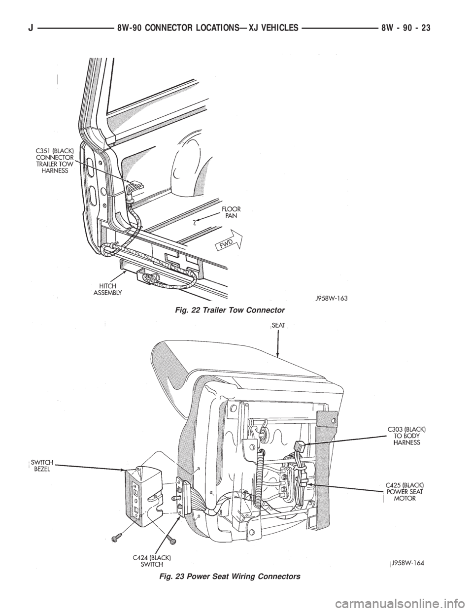
Fig. 22 Trailer Tow Connector
Fig. 23 Power Seat Wiring Connectors
J8W-90 CONNECTOR LOCATIONSÐXJ VEHICLES 8W - 90 - 23
Page 814 of 2198
WIRING DIAGRAMS
CONTENTS
page page
8W-01 GENERAL INFORMATIONÐWIRING
DIAGRAMS...................... 8W-01-1
8W-10 FUSE/FUSE BLOCK........... 8W-10-1
8W-11 POWER DISTRIBUTION........ 8W-11-1
8W-15 GROUND DISTRIBUTION....... 8W-15-1
8W-20 CHARGING SYSTEM.......... 8W-20-1
8W-21 STARTING SYSTEM........... 8W-21-1
8W-30 FUEL/IGNITION.............. 8W-30-1
8W-31 TRANSMISSION CONTROLS.... 8W-31-1
8W-32 ANTI-LOCK BRAKES........... 8W-32-1
8W-33 VEHICLE SPEED CONTROL..... 8W-33-1
8W-40 INSTRUMENT CLUSTER....... 8W-40-1
8W-41 HORN/CIGAR LIGHTER........ 8W-41-1
8W-42 AIR CONDITIONING/HEATER.... 8W-42-1
8W-44 INTERIOR LIGHTING.......... 8W-44-1
8W-47 AUDIO SYSTEM.............. 8W-47-18W-48 HEATED REAR WINDOW....... 8W-48-1
8W-49 OVERHEAD CONSOLE.......... 8W-49-1
8W-50 FRONT LIGHTING............ 8W-50-1
8W-51 REAR LIGHTING............. 8W-51-1
8W-52 TURN SIGNALS.............. 8W-52-1
8W-53 WIPERS.................... 8W-53-1
8W-54 TRAILER TOW................ 8W-54-1
8W-60 POWER WINDOWS............ 8W-60-1
8W-61 POWER DOOR LOCKS......... 8W-61-1
8W-62 POWER MIRRORS............ 8W-62-1
8W-63 POWER SEAT................ 8W-63-1
8W-70 SPLICE INFORMATION........ 8W-70-1
8W-80 CONNECTOR PIN OUTS....... 8W-80-1
8W-90 CONNECTOR LOCATIONS...... 8W-90-1
8W-95 SPLICE LOCATIONS........... 8W-95-1
HOW TO USE THIS GROUP
The purpose of this group is to show the electrical
circuits in a clear, simple fashion and to make trou-
bleshooting easier. Components that work together
are shown together. All electrical components used in
a specific system are shown on one diagram. The feed
for a system is shown at the top of the page. All
wires, connectors, splices, and components are shown
in the flow of current to the bottom of the page. Wir-
ing which is not part of the circuit represented is ref-
erenced to another page/section, where the complete
circuit is shown. In addition, all switches, compo-
nents, and modules are shown in theat rest posi-
tion with the doors closed and the key removed
from the ignition.
If a component is part of several different circuits,
it is shown in the diagram for each. For example, the
headlamp switch is the main part of the exterior
lighting, but it also affects the interior lighting and
the chime warning system.
It is important to realize that no attempt is
made on the diagrams to represent components
and wiring as they appear on the vehicle. For
example, a short piece of wire is treated the
same as a long one. In addition, switches and
other components are shown as simply as pos-
sible, with regard to function only.
The wiring diagram show circuits for all wheel-
bases. If there is a difference in systems or compo-
nents between wheel-bases, an identifier is placed
next to the component.
SECTION IDENTIFICATION
Sections in Group 8W are organized by sub-sys-
tems. The sections contain circuit operation descrip-
tions, helpful information, and system diagrams. The
intention is to organize information by system, con-
sistently from year to year.
CONNECTOR LOCATIONS
Section 8W-90 contains Connector Location illus-
trations. The illustrations contain the connector
number and component identification. Connector Lo-
cation charts in Section 8W-90 reference the illustra-
tion number for components and connectors.
Section 8W-80 shows each connector and the cir-
cuits involved with that connector. The connectors
are identified using the number on the Diagram
pages.
SPLICE LOCATIONS
Splice Location charts in Section 8W-70 show the
entire splice, and provide references to other sections
the splice serves.
Section 8W-95 contains illustrations that show the
general location of the splices in each harness. The
illustrations show the splice by number, and provide
a written location.
JWIRING DIAGRAMSÐXJ-RHD 8W - 1 - 1
Page 885 of 2198
LOW WASHER FLUID WARNING LAMP
Circuit G29 connects the low washer fluid switch to
the warning lamp in the instrument cluster. Circuit
F12 supplies battery voltage to the switch.
When the low washer fluid switch closes, it con-
nects circuits G29 and F12. Battery voltage from cir-
cuit F12 powers the low washer fluid lamp. Circuit
Z1 at the instrument cluster provides ground to illu-
minate the warning lamp.
SEAT BELT INDICATOR WARNING LAMP
The seat belt indicator warning lamp is activated
by the chime/buzzer on circuit G11. Circuit G11 sup-
plies power to instrument cluster for the lamp. Cir-
cuit Z1 provides ground for the lamp at the cluster.
The chime/buzzer module powers circuit G11 after
it receives an input on circuit G10 indicating the seat
belt switch is open.
HIGH-BEAM INDICATOR LAMP
Circuit L3 supplies power for the high beam indi-
cator lamp. The ground path for the lamp is through
circuit Z1. Circuit Z1 provides ground for the indica-
tor lamp at the cluster.
ABS WARNING LAMP
Circuit F87 provides power for the ABS warning
lamp at the instrument cluster. Ground for the ABS
warning lamp is provided by either the ABS control
module or by the ABS power relay when the relay is
not energized. The ABS control module illuminates
the lamp by providing ground on circuit B205.
Circuit B205 splices to connect to circuit B235
through a diode. When the ABS power relay is not
energized, it connects circuit B235 to circuit Z12. The
ground path for the warning lamp is through the di-
ode to circuit B235, through the ABS power relay to
ground on circuit Z12.
The diode between circuits B205 and B235 pre-
vents voltage from flowing to the ABS control module
when the ABS power relay switches to supply power
on circuit B235.
TURN SIGNAL INDICATOR LAMPS
Circuits L61 and L60 power for the turn signal in-
dicator lamps. Circuit L61 powers the left indicator
lamp. Circuit L60 powers the right indicator lamp.
Circuit Z1 provides ground for the lamps.
BRAKE WARNING LAMP
Circuit F87 supplies power to the park brake lamp.
Ground for the park brake lamp is supplied through
the case grounded park brake switch or brake warn-
ing switch on circuit G9. Circuit G9 connects to the
brake warning lamp at the instrument cluster.
FOUR-WHEEL DRIVE (4WD) SWITCH
When the 4WD switch closes, circuit Z1 provides
ground for the 4WD indicator lamp in the instrument
cluster. Circuit F87 connects to the instrument clus-
ter and supplies battery voltage to the 4WD indicator
lamp. Circuit G107 connects the indicator lamp to
the 4WD switch. Circuit G106 connects the lamp to
the instrument cluster and circuit F87.
TACHOMETER
The Powertrain Control Module (PCM) supplies the
signal to the tachometer on circuit G21. Circuit G21
connects to cavity 43 of the PCM.
CLUSTER GROUND
Circuit Z1 from the instrument cluster left connec-
tor provides ground for the illumination lamps and
indicator lamps.
HELPFUL INFORMATION
²If the warning lamps don't operate, check fuse 26
in the fuse block.
²If the indicator lamps don't operate, check fuse 14
in the fuse block.
²If the illumination lamps don't operate, check fuse
25 in the fuse block.
8W - 40 - 2 8W-40 INSTRUMENT CLUSTERÐXJ-RHDJ
Page 909 of 2198
CHIME/BUZZER MODULE
The buzzer or optional chime module sounds an au-
dible warning tone. The tone sounds for seat belt
warning and when the ignition key is in the ignition
switch while the drivers door is open. The tone also
sounds when the ignition key is in the ON position
while the drivers side seat belt is not buckled. Lastly,
the tone sounds when the headlamps are ON when
the ignition is OFF. Refer to Group 8U for system op-
eration.
When the ignition switch is in the RUN or START
position, fuse F87 from fuse 26 in the fuse block sup-
plies power to the chime/buzzer module. Circuit A21
from the ignition switch supplies power to fuse 26.
Circuit L7 from fuse 9 in the fuse block also sup-
plies power to the chime/buzzer module. Circuit A3
from fuse 5 in the Power Distribution Center (PDC)
powers fuse 9.
When the parking lamps or headlamps are ON, the
headlamp switch connects circuit G26 with the driv-
ers side door jamb switch. Circuit G26 also connects
to the key-in switch. Circuit M11 connects the key-in
switch to the chime module and the headlamp
switch.
If the headlamps are ON, and the drivers door
opens, ground for the chime/buzzer is on circuit C26
from the headlamp switch through the door jamb
switch to circuit Z1.
If the headlamps are OFF with the key in the ig-
nition while the drivers side door is open, ground for
the chime/buzzer is supplied through the key-in
switch. The ground path is over circuit M11, through
the closed key-in switch to circuit C26. From circuit
C26, the ground path continues through the drivers
door jamb switch to circuit Z1.
Circuit G11 from the buzzer powers the seat belt
warning lamp in the instrument cluster. Circuit Z1
at the instrument cluster provides ground for the
lamp.Circuit G10 from the buzzer connects to the seat
belt switch. When the seat belt switch closes a path
to ground is completed on circuit Z1 and the tone
sounds momentarily.
Circuit Z1 also grounds the chime buzzer module.
HELPFUL INFORMATION
Circuit F87 also powers the instrument cluster and
the headlamp delay module.
DIAGRAM INDEX
Component Page
Cargo Lamp............................8W-44-6
Chime/Buzzer Module......................8W-44-3
Courtesy Lamps.........................8W-44-5
Dome Lamp............................8W-44-6
Door Jamb Switches......................8W-44-7
Fuse 3 (PDC)...........................8W-44-6
Fuse 5 (PDC).........................8W-44-5, 8
Fuse 6 (PDC)...........................8W-44-6
Fuse 9 (Fuse Block).....................8W-44-3, 8
Fuse 16 (PDC)........................8W-44-4, 6
Fuse 25 (Fuse Block)......................8W-44-8
Fuse 26 (Fuse Block)......................8W-44-3
Glove Box Lamp and Switch.................8W-44-5
Headlamp Switch....................8W-44-3, thru 8
Headlamp Delay Module....................8W-44-3
Ignition Switch..........................8W-44-3
Instrument Cluster......................8W-44-3, 9
Instrument Panel Illumination Lamps..........8W-44-8, 9
Key-In Switch...........................8W-44-4
Liftgate Switch..........................8W-44-6
Reading Lamps..........................8W-44-6
Seat Belt Switch.........................8W-44-3
Telltale Connector (Instrument Cluster)...........8W-44-3
Time Delay Relay........................8W-44-4
Underhood Lamp.........................8W-44-4
8W - 44 - 2 8W-44 INTERIOR LIGHTINGÐXJ-RHDJ
Page 972 of 2198
POWER MIRRORS
INDEX
page page
Diagram Index............................ 1
Heater Elements........................... 1Power Mirrors............................. 1
POWER MIRRORS
Four switches operates the left and right power
mirrors. One switch selects right or left mirror. Each
mirror has two motors; a LEFT/RIGHT motor and a
UP/DOWN motor. The motors switch polarity to al-
low mirror adjustment.
Circuit A7 from fuse 13 in the Power Distribution
Center (PDC) supplies battery voltage to fuse 8 in
the fuse block. Fuse 8 supplies voltage to circuit P60.
Circuit P60 powers the power mirror switch. Circuit
Z1 connects to the power mirror switch and supplies
ground for the power mirror system.
RIGHT POWER MIRROR OPERATION
In the right position, the power mirror switch sup-
plies power to the right mirror LEFT/RIGHT motor
on circuit P79 when a rightward adjustment is made.
Circuit P77 provides the ground path the for right-
ward adjustments.
When the operator makes leftward adjustment, po-
larity reverses. For leftward adjustments, the switch
supplies battery voltage to the right mirror LEFT/
RIGHT motor on circuit P77. Circuit P79 supplies
ground for leftward adjustments.
During upward adjustments, the switch supplies
voltage to the right mirror UP/DOWN motor on cir-
cuit P79. Circuit P80 supplies ground during upward
adjustments.
For downward adjustments, the polarity is re-
versed, the switch powers the right mirror UP/
DOWN motor on circuit P80. Circuit P79 supplies the
ground path.
LEFT POWER MIRROR OPERATION
In the left position, the power mirror switch sup-
plies power to the left mirror LEFT/RIGHT motor on
circuit P79 when a rightward adjustment is made.
Circuit P81 provides the ground path the for right-
ward adjustments.
When the operator makes leftward adjustment, po-
larity reverses. For leftward adjustments, the switch
supplies battery voltage the left mirror LEFT/RIGHT
motor on circuit P81. Circuit P79 supplies ground for
leftward adjustments.
During upward adjustments, the switch supplies
voltage to the left mirror UP/DOWN motor on circuit
P79. Circuit P78 supplies ground during upward ad-
justments.For downward adjustments, the polarity is re-
versed, the switch powers the left mirror UP/DOWN
motor on circuit P78. Circuit P79 supplies the ground
path.
HELPFUL INFORMATION
²Check fuse 3 in the PDC and fuse 8 in the fuse
block in the PDC
HEATER ELEMENTS
The heated rear window relay powers the heater
elements in power mirrors. When the relay energizes,
it supplies power to the heater elements on circuit
C15. Circuit Z1 provides ground for the power mirror
heater elements.
HELPFUL INFORMATION
²Circuit F82 from fuse 2 in the fuse block powers
circuit C15 when the heated rear window relay ener-
gizes.
²Circuit A4 from fuse 7 in the Power Distribution
Center (PDC) supplies battery voltage to the fuse
block for fuse 2 and circuit F85.
²Check fuse 2 in the fuse block.
²Check fuse 7 in the PDC.
DIAGRAM INDEX
Component Page
Fuse 1 (Fuse Block).......................8W-63-2
Fuse 3 (PDC)...........................8W-63-2
Power Seat............................8W-63-2
Power Seat Switch.......................8W-63-2
Fuse 2 (Fuse Block).......................8W-62-3
Fuse 3 (PDC)...........................8W-62-2
Fuse 7 (Fuse Block).......................8W-62-2
Fuse 7 (PDC)...........................8W-62-3
Fuse 8 (Fuse Block).......................8W-62-2
Fuse 16 (PDC)..........................8W-62-2
Heated Rear Window Relay..................8W-62-3
Power Mirrors..........................8W-62-2
Power Mirror Heater Elements................8W-62-3
Power Mirror Switch......................8W-62-2
J8W-62 POWER MIRRORSÐXJ-RHD 8W - 62 - 1