1995 JEEP CHEROKEE seat
[x] Cancel search: seatPage 369 of 2198
voltage is supplied to one side of the indicator bulb. A
ground path for the bulb is provided by 3 switches.
The bulb will light when:
²the brake warning switch is closed (indicating un-
equal brake system hydraulic pressures possibly due
to brake fluid leakage)
²the ignition switch is in the START position (bulb
test)
²the parking brake switch is closed (parking brake
is applied).
Refer to Group 5 - Brakes for more information.
FOUR-WHEEL DRIVE INDICATOR LAMP
This lamp lights when the transfer case is engaged
in the 4H or 4L position. Voltage is supplied to one
side of the indicator bulb. A switch on the front axle
disconnect housing is connected to the other side of
the indicator bulb. When the switch is closed, a path
to ground is provided and the indicator bulb lights.
HEADLAMP HIGH BEAM INDICATOR LAMP
The high beam indicator lamp is controlled by the
headlamp dimmer switch. One side of the indicator
bulb is grounded at all times. The other side of the
bulb receives battery feed through the contacts of the
dimmer switch when the turn signal switch lever is
actuated to turn the headlamp high beams on. Refer
to Group 8L - Lamps for more information.
MALFUNCTION INDICATOR LAMP
The CHECK ENGINE or Malfunction Indicator
Lamp (MIL) lights each time the ignition switch is
turned ON, and stays on for 3 seconds as a bulb test.
If the Powertrain Control Module (PCM) receives an
incorrect signal or no signal from certain fuel or
emission system related circuits or components, the
lamp is turned on. This will indicate that the PCM
has recorded a Diagnostic Trouble Code (DTC) in
electronic memory for a circuit or component mal-
function. Refer to Group 14 - Fuel System for more
information.
SEAT BELT REMINDER LAMP
The seat belt reminder lamp lights for 4 to 8 sec-
onds after the ignition switch is turned to the ON po-sition. A timer in the chime/buzzer module controls
ignition-switched battery feed to the lamp. Refer to
Group 8U - Chime/Buzzer Warning Systems for more
information.
TURN SIGNAL INDICATOR LAMPS
The left and right turn signal indicator lamps are
controlled by the turn signal and hazard warning
switches. One side of the bulb for each lamp is
grounded at all times. The other side of the bulb re-
ceives battery feed through the contacts of the turn
signal switch, when the turn signal lever or hazard
warning button are actuated. Refer to Group 8J -
Turn Signal and Hazard Warning Systems for more
information.
UPSHIFT INDICATOR LAMP
Vehicles equipped with manual transmissions have
an optional upshift indicator lamp. Ground feed for
the lamp is switched by the Powertrain Control Mod-
ule (PCM). The lamp lights to indicate when the
driver should shift to the next highest gear for best
fuel economy. The PCM will turn the lamp off after 3
to 5 seconds if the upshift is not performed. The lamp
will remain off until the vehicle stops accelerating
and is brought back to the range of lamp operation,
or until the transmission is shifted into another gear.
The indicator lamp is normally on when the igni-
tion switch is turned ON and is turned off when the
engine is started. The lamp will be turned on during
vehicle operation according to engine speed and load.
CLUSTER ILLUMINATION LAMPS
All cluster illumination lamps receive battery feed
from the instrument lamps fuse in the fuseblock
module through the panel dimmer switch. When the
park or headlamps are on, the cluster illumination
lamps light. Illumination brightness can be adjusted
by rotating the panel dimmer thumb-wheel, which is
next to the headlamp switch.
8E - 26 INSTRUMENT PANEL AND GAUGESÐYJJ
Page 376 of 2198
(9) Turn ignition switch to START position and
hold there. Check for continuity between terminal for
circuit G11 of ignition switch and a good ground.
There should be continuity. If not OK, replace igni-
tion switch.
(10) Unplug brake warning switch connector.
Check for continuity between parking brake switch
connector and a good ground. There should be no
continuity. If OK, go to next step. If not OK, repair
short circuit as required.
(11) Check for continuity between parking brake
switch connector and brake warning switch connector
cavity for circuit G11. There should be continuity. If
OK, replace parking brake switch. If not OK, repair
open circuit to brake warning switch as required.
FOUR-WHEEL DRIVE INDICATOR LAMP
(1) Apply parking brake, start engine, vehicle in
4WD Lock or 4WD.
(2) Unplug switch and touch harness side of wire
to ground. Lamp should light. If OK, check switch
operation, replace if bad. If bulb is OK, repair open
to indicator.
HEADLAMP HIGH BEAM INDICATOR LAMP
(1) Check that headlamp high beams are func-
tional. If OK, go to next step. If not OK, refer to
Group 8L - Lamps for diagnosis of headlamp system.
(2) Disconnect battery negative cable. Remove left
instrument cluster bezel and main cluster assembly.
Unplug cluster connector. Connect battery negative
cable. Turn headlamps on and select high beam.
Check for battery voltage at cavity 17 of cluster con-
nector. If OK, replace indicator bulb. If not OK, re-
pair circuit to headlamp dimmer switch as required.
MALFUNCTION INDICATOR LAMP
The diagnosis found here addresses an inoperative
lamp condition. If the lamp comes on and stays on
with engine running, refer to Group 14 - Fuel System
for diagnosis. If no fuel or emission system problem
is found, the following procedure will help locate a
short or open in the lamp circuit.
(1) Disconnect battery negative cable. Unplug PCM
connector. Install a jumper wire from cavity 32 of
PCM connector (Fig. 5) to a good ground. Connect
battery negative cable. Turn ignition switch to ON.
Lamp should light. Remove jumper wire and lamp
should go OFF. If OK, refer to Powertrain Diagnostic
Procedures to check PCM. If not OK, go to next step.
(2) Turn ignition switch to OFF. Disconnect battery
negative cable. Remove left instrument cluster bezel
and main cluster assembly. Install a jumper wire
from cavity 2 of cluster connector to a good ground.
Connect battery negative cable. Turn ignition switch
to ON. Lamp should light. If OK, go to next step. If
not OK, replace bulb.(3) Turn ignition switch to OFF. Disconnect battery
negative cable. Unplug cluster connector. Check for
continuity between cavity 2 of cluster connector and
a good ground. There should be no continuity. If OK,
go to next step. If not OK, repair short circuit to
PCM as required.
(4) Check continuity between cavity 2 of cluster
connector and cavity 32 of PCM connector. There
should be continuity. If not OK, repair open circuit to
PCM as required.
SEAT BELT REMINDER LAMP
(1) Refer to Group 8U - Chime/Buzzer Warning
Systems to check chime/buzzer module operation. If
OK, go to next step. If not OK, replace chime/buzzer
module.
(2) Disconnect battery negative cable. Remove left
instrument cluster bezel and main cluster assembly.
Unplug cluster connector. Check for continuity be-
tween cavity 20 of cluster connector and a good
ground. There should be continuity. If OK, plug clus-
ter connector back into cluster and go to next step. If
not OK, repair open circuit to ground as required.
(3) Connect battery negative cable. Install a
jumper wire between a 12-volt battery feed and cav-
ity 16 of cluster connector. Lamp should light. If OK,
go to next step. If not OK, replace bulb.
(4) Disconnect battery negative cable. Unplug
chime/buzzer module from fuseblock module. Unplug
cluster connector. Check for continuity between cav-
ity 16 of cluster connector and a good ground. There
should be no continuity. If OK, go to next step. If not
OK, repair short circuit to chime/buzzer module as
required.
(5) Check continuity between cavity 16 of cluster
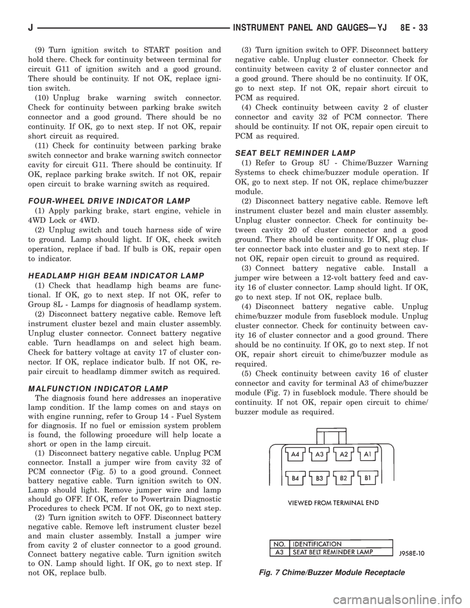
connector and cavity for terminal A3 of chime/buzzer
module (Fig. 7) in fuseblock module. There should be
continuity. If not OK, repair open circuit to chime/
buzzer module as required.
Fig. 7 Chime/Buzzer Module Receptacle
JINSTRUMENT PANEL AND GAUGESÐYJ 8E - 33
Page 464 of 2198
DOME LAMP REPLACEMENTÐXJ
REMOVAL
(1) Remove the dome lamp lens by squeezing it at
both sides. This will separate the lens retainer tabs
from the lamp housing shoulders.
(2) Pull the lens downward to remove it from the
lamp housing.
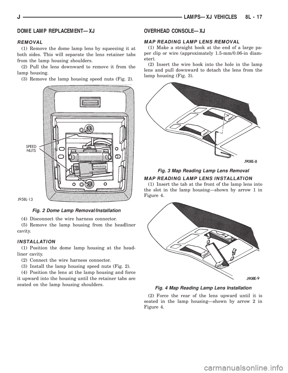
(3) Remove the lamp housing speed nuts (Fig. 2).
(4) Disconnect the wire harness connector.
(5) Remove the lamp housing from the headliner
cavity.
INSTALLATION
(1) Position the dome lamp housing at the head-
liner cavity.
(2) Connect the wire harness connector.
(3) Install the lamp housing speed nuts (Fig. 2).
(4) Position the lens at the lamp housing and force
it upward into the housing until the retainer tabs are
seated on the lamp housing shoulders.
OVERHEAD CONSOLEÐXJ
MAP READING LAMP LENS REMOVAL
(1) Make a straight hook at the end of a large pa-
per clip or wire (approximately 1.5-mm/0.06-in diam-
eter).
(2) Insert the wire hook into the hole in the lamp
lens and pull downward to detach the lens from the
lamp housing (Fig. 3).
MAP READING LAMP LENS INSTALLATION
(1) Insert the tab at the front of the lamp lens into
the slot in the lamp housingÐshown by arrow 1 in
Figure 4.
(2) Force the rear of the lens upward until it is
seated in the lamp housingÐshown by arrow 2 in
Figure 4.
Fig. 2 Dome Lamp Removal/Installation
Fig. 3 Map Reading Lamp Lens Removal
Fig. 4 Map Reading Lamp Lens Installation
JLAMPSÐXJ VEHICLES 8L - 17
Page 465 of 2198
BULB APPLICATIONÐXJ VEHICLES
GENERAL INFORMATION
The following Bulb Application Table lists the lamp
title on the left side of the column and trade number
or part number on the right.
CAUTION: Do not use bulbs that have a higher can-
dle power than the bulb listed in the Bulb Applica-
tion Table. Damage to lamp can result.
Do not touch halogen bulbs with fingers or other
oily surfaces. Bulb life will be reduced.
EXTERIOR LAMPSÐXJ
Back-up .................................................................1156
Center High Mounted Stoplamp ..........................922
Fog ............................................................................H3
Front Side Marker .................................................194
Headlamp/Sealed Beam....................................H6054
License Plate ..........................................................168
License Plate W/Outside Spare ..............................67
Park/Turn Signal ............................................2057NA
Tail/Stop ................................................................2057
Turn Signal ...........................................................1156
INTERIOR LAMPSÐXJ
Service procedures for most of the lamps in the in-
strument panel, Instrument cluster and switches are
located in Group 8E, Instrument Panel and Gauges.
Some components have lamps that can only be ser-
viced by an Authorized Service Center (ASC) after
the component is removed from the vehicle. Contact
local dealer for location of nearest ASC.
Cargo .......................................................................561
Dome .......................................................................561
Dome/Reading.........................................................906Glove Compartment ...............................................194
Overhead Console ..................................................912
Under Hood ............................................................105
Vanity Mirror ...........................................................74
Underpanel Courtesy.............................................168
INDICATOR LAMPS
Service procedures for most of the lamps in the in-
strument panel, instrument cluster and switches are
located in Group 8E, Instrument Panel and Gauges.
A/C Control ...............................................................74
Airbag ........................................................................74
Anti-lock Brake ........................................................74
Ash Receiver .........................................................1891
Brake Warning .........................................................74
Check Engine ...........................................................74
Cigar Lighter ............................................................53
Diesel Wait ...............................................................74
Fasten Seat Belts ....................................................74
Four Wheel Drive ....................................................74
Generator ................................................................194
Generator/Diesel.......................................................74
Heater Control .........................................................74
High Beam..............................................................194
Illumination ............................................................194
Low Fuel .................................................................194
Low Washer Fluid....................................................74
Radio ......................................................................ASC
Rocker Switch...........................................................37
Seat Belt ...................................................................74
Transfer Case .........................................................658
Transmission Floor Shift.......................................658
Turn Signal.............................................................194
Shift ...........................................................................74
Water In Fuel ...........................................................74
8L - 18 LAMPSÐXJ VEHICLESJ
Page 478 of 2198
INTERIOR LAMPS
INDEX
page page
Dome/Courtesy Lamp Service InformationÐYJ . . . 31
Dome/Courtesy Lamp Trouble DiagnosisÐYJ.... 31Hardtop Dome/Cargo Lamp Bulb ReplacementÐYJ
Vehicles............................... 31
DOME/COURTESY LAMP SERVICE
INFORMATIONÐYJ
The dome/cargo and underpanel courtesy lamps are
controlled via ON/OFF switches. The ON/OFF
switches are in the lamp ground circuits. Voltage via
the dome/courtesy lamp fuse is applied directly to the
lamp bulbs. When either door is opened, the door pil-
lar switch contacts close and provide a direct path to
vehicle body ground.
The dome/cargo and underpanel courtesy lamps
can also be turned on via the interior lamp illumina-
tion rheostat.
DOME/COURTESY LAMP TROUBLE DIAGNOSISÐ
YJ
ALL LAMPS INOPERATIVE FROM INTERIOR
LAMP ILLUMINATION RHEOSTAT
(1) Rotate the interior lamp illumination rheostat
in an upward direction. The lamps should light. If
not OK, remove, inspect and test the dome lamp
fuse. Replace if bad.
(2) If the fuse is OK, repair the open circuit in the
wire harness to vehicle body ground.
(3) If lamp still does not light, replace the switch.
ONE LAMP INOPERATIVE
(1) Measure the resistance across the bulb holder
terminals. The ohmmeter should indicate zero ohms.
If not, replace the bulb.
(2) Measure the voltage between the voltage side
of the bulb holder and vehicle body ground. The volt-
meter should indicate battery voltage. If not, repair
the open circuit in the wire harness to the splice.
LAMPS INOPERATIVE WITH ONE OR MORE
DOORS OPENED
(1) Remove the inoperative switch from the door
pillar and connect the switch wire directly to ground.
The lamp should light.(2) If not, check for an open circuit in black
(ground) wire. Repair as necessary. If lamps still do
not light, replace the switch.
HARDTOP DOME/CARGO LAMP BULB
REPLACEMENTÐYJ VEHICLES
REMOVAL
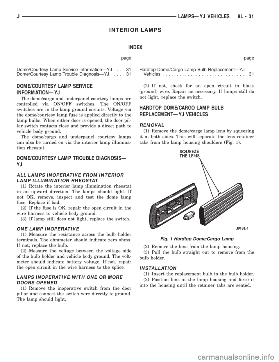
(1) Remove the dome/cargo lamp lens by squeezing
it at both sides. This will separate the lens retainer
tabs from the lamp housing shoulders (Fig. 1).
(2) Remove the lens from the lamp housing.
(3) Pull the bulb straight out to remove from the
bulb holder.
INSTALLATION
(1) Insert the replacement bulb in the bulb holder.
(2) Position lens at the lamp housing and force it
into the housing until the retainer tabs are seated.
Fig. 1 Hardtop Dome/Cargo Lamp
JLAMPSÐYJ VEHICLES 8L - 31
Page 479 of 2198

BULB APPLICATIONÐYJ VEHICLES
GENERAL INFORMATION
The following Bulb Application Table lists the lamp
title on the left side of the column and trade number
or part number on the right.
CAUTION: Do not use bulbs that have a higher can-
dle power than the bulb listed in the Bulb Applica-
tion Table. Damage to lamp can result.
Do not touch halogen bulbs with fingers or other
oily surfaces. Bulb life will be reduced.
EXTERIOR LAMPSÐYJ
Back-up .................................................................1156
Center High Mounted Stoplamp ..........................912
Fog ............................................................................H3
Front Side Marker .................................................194
Headlamp/Sealed Beam....................................H6054
Park/Turn Signal..................................................3157
Tail/Stop ................................................................1157
INTERIOR LAMPSÐYJ
Service procedures for most of the lamps in the in-
strument panel, Instrument cluster and switches are
located in Group 8E, Instrument Panel and Gauges.
Some components have lamps that can only be ser-
viced by an Authorized Service Center (ASC) after
the component is removed from the vehicle. Contact
local dealer for location of nearest ASC.Dome/Cargo .........................................................212-2
Glove Compartment ...............................................194
Under Hood ............................................................105
Underpanel Courtesy...............................................89
INDICATOR LAMPS
Service procedures for most of the lamps in the in-
strument panel, instrument cluster and switches are
located in Group 8E, Instrument Panel and Gauges.
A/C Control ...............................................................74
Anti-lock Brake ........................................................74
Ash Receiver .........................................................1891
Brake Warning .........................................................74
Cigar Lighter ............................................................53
Fasten Seat Belts ....................................................74
Four Wheel Drive ....................................................74
Generator ................................................................194
Hazard.......................................................................74
Heater Control .......................................................194
High Beam..............................................................194
Illumination ............................................................194
Low Coolant..............................................................74
Radio ......................................................................ASC
Rocker Switch...........................................................74
Seat Belt ...................................................................74
Shift ...........................................................................74
Turn Signal.............................................................194
8L - 32 LAMPSÐYJ VEHICLESJ
Page 500 of 2198
POWER SEATS
CONTENTS
page page
DIAGNOSIS............................. 2
GENERAL INFORMATION.................. 1SERVICE PROCEDURES................... 3
GENERAL INFORMATION
A six-way driver's side power seat is an available
option on XJ (Cherokee) models. The power seat sys-
tem receives battery feed through fuse 6 in the power
distribution center and circuit breaker 16 in the fuse-
block module at all times.
Following are general descriptions of the major
components in the power seat system. Refer to Group
8W - Wiring Diagrams for complete circuit descrip-
tions and diagrams.
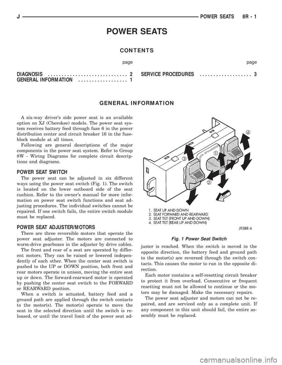
POWER SEAT SWITCH
The power seat can be adjusted in six different
ways using the power seat switch (Fig. 1). The switch
is located on the lower outboard side of the seat
cushion. Refer to the owner's manual for more infor-
mation on power seat switch functions and seat ad-
justing procedures. The individual switches cannot be
repaired. If one switch fails, the entire switch module
must be replaced.
POWER SEAT ADJUSTER/MOTORS
There are three reversible motors that operate the
power seat adjuster. The motors are connected to
worm-drive gearboxes in the adjuster by drive cables.
The front and rear of a seat are operated by differ-
ent motors. They can be raised or lowered indepen-
dently of each other. When the center seat switch is
pushed to the UP or DOWN position, both front and
rear motors operate in unison, moving the entire seat
up or down. The forward-rearward motor is operated
by pushing the center seat switch to the FORWARD
or REARWARD position.
When a switch is actuated, battery feed and a
ground path are applied through the switch contacts
to the motor(s). The motor(s) operate to move the
seat in the selected direction until the switch is re-
leased, or until the travel limit of the power seat ad-juster is reached. When the switch is moved in the
opposite direction, the battery feed and ground path
to the motor(s) are reversed through the switch con-
tacts. This causes the motor to run in the opposite di-
rection.
Each motor contains a self-resetting circuit breaker
to protect it from overload. Consecutive or frequent
resetting must not be allowed to continue or the mo-
tors may be damaged. Make the necessary repairs.
The power seat adjuster and motors can not be re-
paired, and are serviced only as a complete unit. If
any component in this unit should fail, the entire as-
sembly must be replaced.
Fig. 1 Power Seat Switch
JPOWER SEATS 8R - 1
Page 501 of 2198
DIAGNOSIS
Before any testing is attempted the battery should
be fully charged and all connections and pins cleaned
and tightened to ensure proper continuity and
grounds.
With the dome lamp on, apply switch in direction
of the failure. If the dome lamp dims, the seat may
be jamming. Check for binding or obstructions. If the
dome lamp does not dim, then proceed with the fol-
lowing electrical tests.
POWER SEAT ADJUSTER/MOTORS
Operate the power seat switch to move all three
seat motors. The seat should move in all directions.
If not OK, proceed as follows. If one or more motors
operate, see diagnosis for Power Seat Switch.
(1) Check circuit breaker 16 in the fuseblock mod-
ule. If OK, go to next step. If not OK, replace circuit
breaker.
(2) Remove switch mounting screws and check for
battery voltage at red wire at switch connector. If
OK, go to next step. If not OK, repair wiring to cir-
cuit breaker.(3) Check for continuity between black wire at
switch connector and a good ground. There should be
continuity. If OK, go to next step. If not OK, repair
wiring to ground.
(4) See diagnosis for Power Seat Switch. If switch
continuity checks OK, replace faulty motor/adjuster
assembly. If switch continuity is not OK, replace
faulty switch.
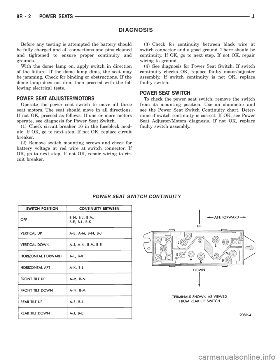
POWER SEAT SWITCH
To check the power seat switch, remove the switch
from its mounting position. Use an ohmmeter and
see the Power Seat Switch Continuity chart. Deter-
mine if switch continuity is correct. If OK, see Power
Seat Adjuster/Motors diagnosis. If not OK, replace
faulty switch assembly.
POWER SEAT SWITCH CONTINUITY
8R - 2 POWER SEATSJ