1995 JEEP CHEROKEE seat
[x] Cancel search: seatPage 177 of 2198
CAUTION: The mercury switch (inside the accelera-
tion switch), will not function properly if the switch
is mispositioned. Verify that the switch locating ar-
row is pointing to the front of the vehicle.
(2) Position switch in mounting bracket.
(3) Install and tighten switch attaching screws to
2-4 Nzm (17-32 in. lbs.) torque.
(4) Connect harness to switch. Be sure harness
connecter is firmly seated.
(5) Move seat back to normal position.
ECU REMOVAL (XJ MODELS)
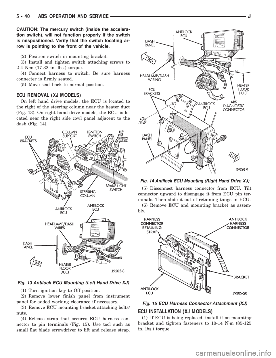
On left hand drive models, the ECU is located to
the right of the steering column near the heater duct
(Fig. 13). On right hand drive models, the ECU is lo-
cated near the right side cowl panel adjacent to the
dash (Fig. 14).
(1) Turn ignition key to Off position.
(2) Remove lower finish panel from instrument
panel for added working clearance if necessary.
(3) Remove ECU mounting bracket attaching bolts/
nuts.
(4) Release strap that secures ECU harness con-
nector to pin terminals (Fig. 15). Use tool such as
small flat blade screwdriver to lift and release strap.(5) Disconnect harness connector from ECU. Tilt
connector upward to disengage it from ECU pin ter-
minals. Then slide it out of retaining tangs in ECU.
(6) Remove ECU and mounting bracket as assem-
bly.
ECU INSTALLATION (XJ MODELS)
(1) If ECU is being replaced, install it on mounting
bracket and tighten fasteners to 10-14 Nzm (85-125
in. lbs.) torque
Fig. 13 Antilock ECU Mounting (Left Hand Drive XJ)
Fig. 14 Antilock ECU Mounting (Right Hand Drive XJ)
Fig. 15 ECU Harness Connector Attachment (XJ)
5 - 40 ABS OPERATION AND SERVICEJ
Page 184 of 2198
(8) Remove outboard shoe. Press one end of shoe
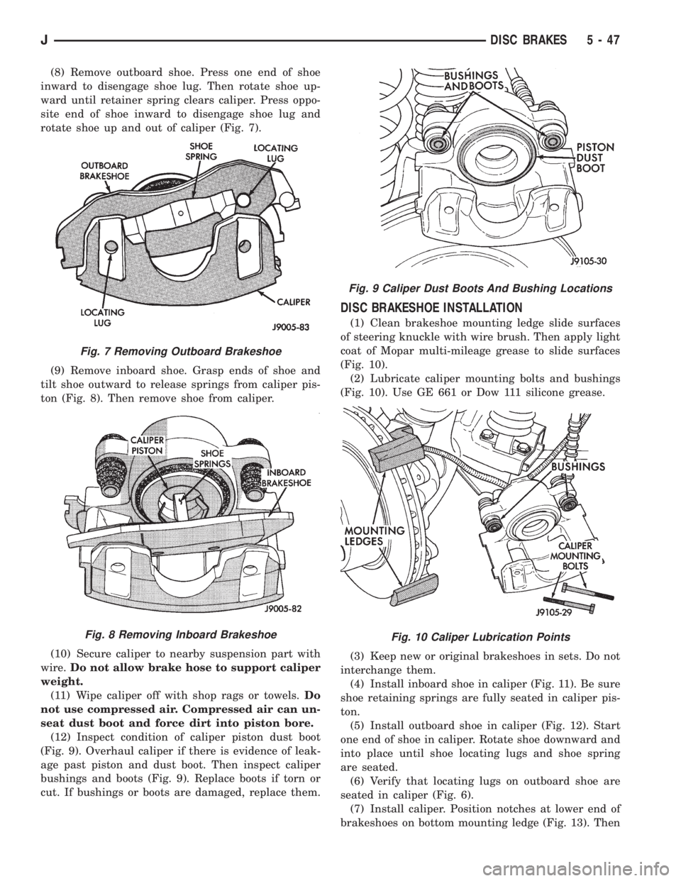
inward to disengage shoe lug. Then rotate shoe up-
ward until retainer spring clears caliper. Press oppo-
site end of shoe inward to disengage shoe lug and
rotate shoe up and out of caliper (Fig. 7).
(9) Remove inboard shoe. Grasp ends of shoe and
tilt shoe outward to release springs from caliper pis-
ton (Fig. 8). Then remove shoe from caliper.
(10) Secure caliper to nearby suspension part with
wire.Do not allow brake hose to support caliper
weight.
(11) Wipe caliper off with shop rags or towels.Do
not use compressed air. Compressed air can un-
seat dust boot and force dirt into piston bore.
(12) Inspect condition of caliper piston dust boot
(Fig. 9). Overhaul caliper if there is evidence of leak-
age past piston and dust boot. Then inspect caliper
bushings and boots (Fig. 9). Replace boots if torn or
cut. If bushings or boots are damaged, replace them.
DISC BRAKESHOE INSTALLATION
(1) Clean brakeshoe mounting ledge slide surfaces
of steering knuckle with wire brush. Then apply light
coat of Mopar multi-mileage grease to slide surfaces
(Fig. 10).
(2) Lubricate caliper mounting bolts and bushings
(Fig. 10). Use GE 661 or Dow 111 silicone grease.
(3) Keep new or original brakeshoes in sets. Do not
interchange them.
(4) Install inboard shoe in caliper (Fig. 11). Be sure
shoe retaining springs are fully seated in caliper pis-
ton.
(5) Install outboard shoe in caliper (Fig. 12). Start
one end of shoe in caliper. Rotate shoe downward and
into place until shoe locating lugs and shoe spring
are seated.
(6) Verify that locating lugs on outboard shoe are
seated in caliper (Fig. 6).
(7) Install caliper. Position notches at lower end of
brakeshoes on bottom mounting ledge (Fig. 13). Then
Fig. 7 Removing Outboard Brakeshoe
Fig. 8 Removing Inboard Brakeshoe
Fig. 9 Caliper Dust Boots And Bushing Locations
Fig. 10 Caliper Lubrication Points
JDISC BRAKES 5 - 47
Page 185 of 2198
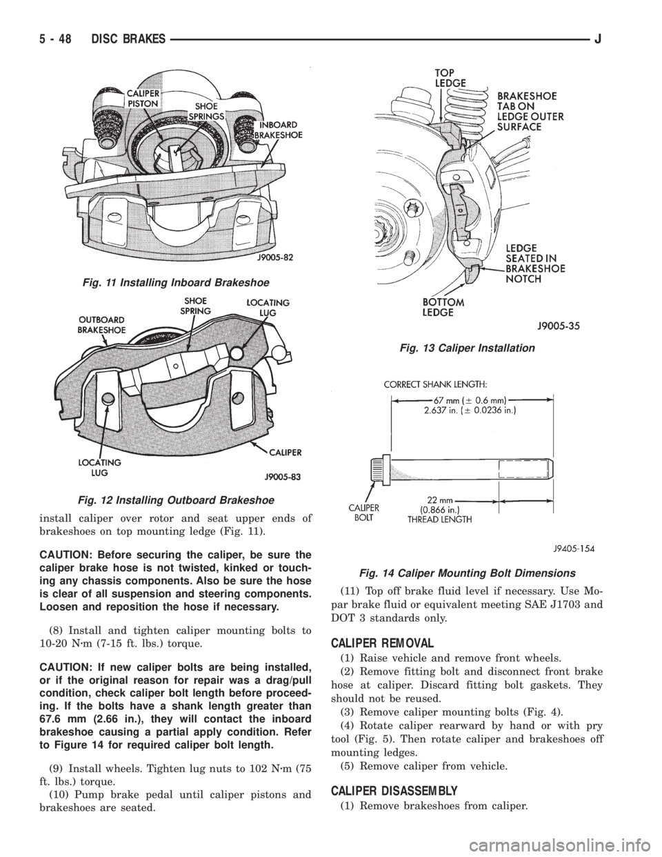
install caliper over rotor and seat upper ends of
brakeshoes on top mounting ledge (Fig. 11).
CAUTION: Before securing the caliper, be sure the
caliper brake hose is not twisted, kinked or touch-
ing any chassis components. Also be sure the hose
is clear of all suspension and steering components.
Loosen and reposition the hose if necessary.
(8) Install and tighten caliper mounting bolts to
10-20 Nzm (7-15 ft. lbs.) torque.
CAUTION: If new caliper bolts are being installed,
or if the original reason for repair was a drag/pull
condition, check caliper bolt length before proceed-
ing. If the bolts have a shank length greater than
67.6 mm (2.66 in.), they will contact the inboard
brakeshoe causing a partial apply condition. Refer
to Figure 14 for required caliper bolt length.
(9) Install wheels. Tighten lug nuts to 102 Nzm (75
ft. lbs.) torque.
(10) Pump brake pedal until caliper pistons and
brakeshoes are seated.(11) Top off brake fluid level if necessary. Use Mo-
par brake fluid or equivalent meeting SAE J1703 and
DOT 3 standards only.
CALIPER REMOVAL
(1) Raise vehicle and remove front wheels.
(2) Remove fitting bolt and disconnect front brake
hose at caliper. Discard fitting bolt gaskets. They
should not be reused.
(3) Remove caliper mounting bolts (Fig. 4).
(4) Rotate caliper rearward by hand or with pry
tool (Fig. 5). Then rotate caliper and brakeshoes off
mounting ledges.
(5) Remove caliper from vehicle.
CALIPER DISASSEMBLY
(1) Remove brakeshoes from caliper.
Fig. 11 Installing Inboard Brakeshoe
Fig. 12 Installing Outboard Brakeshoe
Fig. 13 Caliper Installation
Fig. 14 Caliper Mounting Bolt Dimensions
5 - 48 DISC BRAKESJ
Page 187 of 2198
CALIPER CLEANING AND INSPECTION
Clean the caliper and piston with Mopar brake
cleaner, clean brake fluid, or denatured alcohol only.
Do not use gasoline, kerosene, thinner, or similar sol-
vents. These products leave a residue that will dam-
age pistons and seals.
Wipe the caliper and piston dry with lint free tow-
els or use low pressure compressed air.
Inspect the piston and piston bore. Replace the cal-
iper if the bore is corroded, rusted, pitted, or scored.
Do not hone the caliper piston bore. Replace the cal-
iper if the bore exhibits any of the aforementioned
conditions.
Inspect the caliper piston. The piston is made from
a phenolic resin and should be smooth and clean. Re-
place the piston if cracked, chipped, or scored. Do not
attempt to restore a scored, or corroded piston sur-
face by sanding or polishing. The piston must be re-
placed if damaged.
CAUTION: Never interchange phenolic resin and
steel caliper pistons. The seals, seal grooves, cali-
per bores and piston tolerances are different for
resin and steel pistons. Do not intermix these com-
ponents.
Inspect the caliper mounting bolt bushings and
boots. Replace the boots if cut or torn. Clean and lu-
bricate the bushings with GE 661 or Dow 111 silicone
grease if necessary.
Inspect condition of the caliper mounting bolts. Re-
place the bolts if corroded, rusted, or worn. Do not
reuse the bolts if unsure of their condition.
Length of the caliper mounting bolts is also ex-
tremely important.
Use the replacement bolts specified in the parts
catalog at all times. Do not use substitute bolts. Bolts
that are too long will partially apply the inboard
brakeshoe causing drag and pull. Refer to the caliper
and brakeshoe installation procedures for service de-
tails and bolt dimensions.
CALIPER ASSEMBLY
(1) Coat caliper piston bore, new piston seal and
piston with clean, fresh brake fluid.
(2) Lubricate caliper bushings and interior of bush-
ing boots with GE 661, Dow 111, or Permatex Dielec-
tric silicone grease.
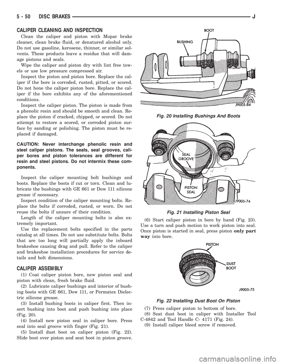
(3) Install bushing boots in caliper first. Then in-
sert bushing into boot and push bushing into place
(Fig. 20).
(4) Install new piston seal in caliper bore. Press
seal into seal groove with finger (Fig. 21).
(5) Install dust boot on caliper piston (Fig. 22).
Slide boot over piston and seat boot in piston groove.(6) Start caliper piston in bore by hand (Fig. 23).
Use a turn and push motion to work piston into seal.
Once piston is started in seal, press pistononly part
wayinto bore.
(7) Press caliper piston to bottom of bore.
(8) Seat dust boot in caliper with Installer Tool
C-4842 and Tool Handle C- 4171 (Fig. 24).
(9) Install caliper bleed screw if removed.
Fig. 20 Installing Bushings And Boots
Fig. 21 Installing Piston Seal
Fig. 22 Installing Dust Boot On Piston
5 - 50 DISC BRAKESJ
Page 188 of 2198
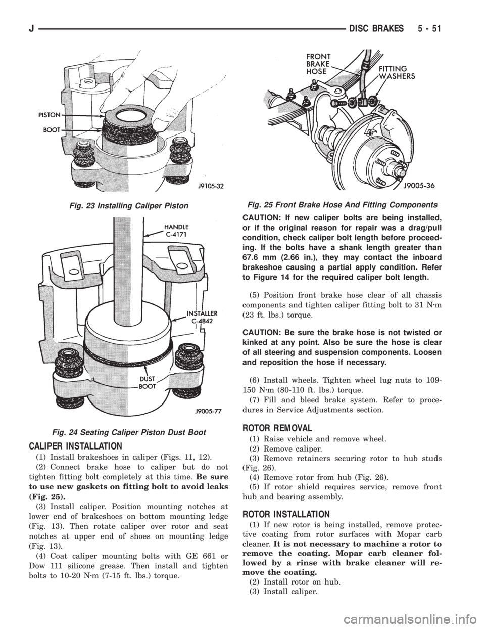
CALIPER INSTALLATION
(1) Install brakeshoes in caliper (Figs. 11, 12).
(2) Connect brake hose to caliper but do not
tighten fitting bolt completely at this time.Be sure
to use new gaskets on fitting bolt to avoid leaks
(Fig. 25).
(3) Install caliper. Position mounting notches at
lower end of brakeshoes on bottom mounting ledge
(Fig. 13). Then rotate caliper over rotor and seat
notches at upper end of shoes on mounting ledge
(Fig. 13).
(4) Coat caliper mounting bolts with GE 661 or
Dow 111 silicone grease. Then install and tighten
bolts to 10-20 Nzm (7-15 ft. lbs.) torque.CAUTION: If new caliper bolts are being installed,
or if the original reason for repair was a drag/pull
condition, check caliper bolt length before proceed-
ing. If the bolts have a shank length greater than
67.6 mm (2.66 in.), they may contact the inboard
brakeshoe causing a partial apply condition. Refer
to Figure 14 for the required caliper bolt length.
(5) Position front brake hose clear of all chassis
components and tighten caliper fitting bolt to 31 Nzm
(23 ft. lbs.) torque.
CAUTION: Be sure the brake hose is not twisted or
kinked at any point. Also be sure the hose is clear
of all steering and suspension components. Loosen
and reposition the hose if necessary.
(6) Install wheels. Tighten wheel lug nuts to 109-
150 Nzm (80-110 ft. lbs.) torque.
(7) Fill and bleed brake system. Refer to proce-
dures in Service Adjustments section.
ROTOR REMOVAL
(1) Raise vehicle and remove wheel.
(2) Remove caliper.
(3) Remove retainers securing rotor to hub studs
(Fig. 26).
(4) Remove rotor from hub (Fig. 26).
(5) If rotor shield requires service, remove front
hub and bearing assembly.
ROTOR INSTALLATION
(1) If new rotor is being installed, remove protec-
tive coating from rotor surfaces with Mopar carb
cleaner.It is not necessary to machine a rotor to
remove the coating. Mopar carb cleaner fol-
lowed by a rinse with brake cleaner will re-
move the coating.
(2) Install rotor on hub.
(3) Install caliper.
Fig. 23 Installing Caliper Piston
Fig. 24 Seating Caliper Piston Dust Boot
Fig. 25 Front Brake Hose And Fitting Components
JDISC BRAKES 5 - 51
Page 191 of 2198
WHEEL NUT TIGHTENING
The wheel attaching nuts must be tightened prop-
erly to ensure efficient brake operation. Overtighten-
ing the nuts or tightening them in the wrong
sequence can cause distortion of the brake rotors and
drums. Impact wrenches are not really recommended
for tightening wheel nuts. A torque wrench should be
used for this purpose.
A light coat of LPS Anti-Corrosion spray lube
around the hub face and on the studs will cut down
on rust/corrosion formation.The correct tightening sequence is important in
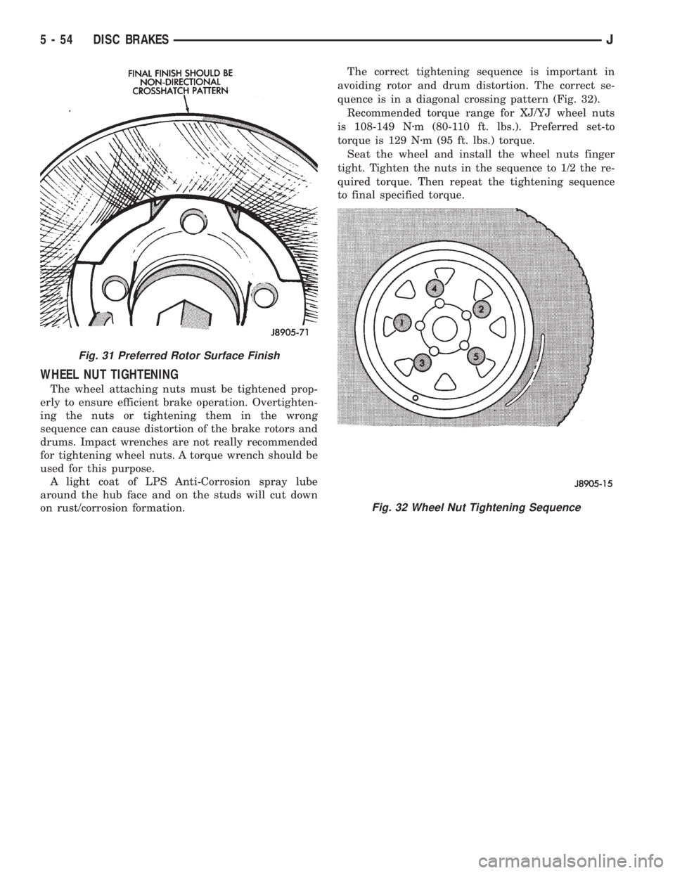
avoiding rotor and drum distortion. The correct se-
quence is in a diagonal crossing pattern (Fig. 32).
Recommended torque range for XJ/YJ wheel nuts
is 108-149 Nzm (80-110 ft. lbs.). Preferred set-to
torque is 129 Nzm (95 ft. lbs.) torque.
Seat the wheel and install the wheel nuts finger
tight. Tighten the nuts in the sequence to 1/2 the re-
quired torque. Then repeat the tightening sequence
to final specified torque.
Fig. 31 Preferred Rotor Surface Finish
Fig. 32 Wheel Nut Tightening Sequence
5 - 54 DISC BRAKESJ
Page 195 of 2198
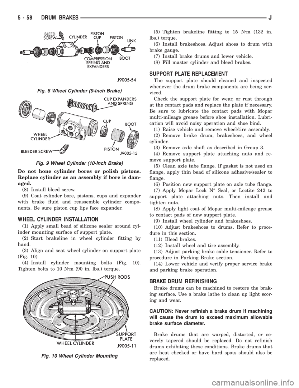
Do not hone cylinder bores or polish pistons.
Replace cylinder as an assembly if bore is dam-
aged.
(8) Install bleed screw.
(9) Coat cylinder bore, pistons, cups and expander
with brake fluid and reassemble cylinder compo-
nents. Be sure piston cup lips face expander.
WHEEL CYLINDER INSTALLATION
(1) Apply small bead of silicone sealer around cyl-
inder mounting surface of support plate.
(2) Start brakeline in wheel cylinder fitting by
hand.
(3) Align and seat wheel cylinder on support plate
(Fig. 10).
(4) Install cylinder mounting bolts (Fig. 10).
Tighten bolts to 10 Nzm (90 in. lbs.) torque.(5) Tighten brakeline fitting to 15 Nzm (132 in.
lbs.) torque.
(6) Install brakeshoes. Adjust shoes to drum with
brake gauge.
(7) Install brake drums and lower vehicle.
(8) Fill master cylinder and bleed brakes.
SUPPORT PLATE REPLACEMENT
The support plate should cleaned and inspected
whenever the drum brake components are being ser-
viced.
Check the support plate for wear, or rust through
at the contact pads and replace the plate if necessary.
Be sure to lubricate the contact pads with Mopar
multi-mileage grease before shoe installation. Lubri-
cation will avoid noisy operation and shoe bind.
(1) Raise vehicle and remove wheel/tire assembly.
(2) Remove brake drum, brakeshoes, and wheel
cylinder.
(3) Remove axle shaft as described in Group 3.
(4) Remove support plate attaching nuts and re-
move support plate.
(5) Clean axle tube flange. If gasket is not used on
flange, apply thin bead of silicone adhesive/sealer to
flange.
(6) Position new support plate on axle tube flange.
(7) Apply Mopar Lock N9Seal, or Loctite 242 to
support plate attaching nuts. Then install and
tighten nuts.
(8) Apply light coat of Mopar multi-mileage grease
to contact pads of new support plate.
(9) Install wheel cylinder and brakeshoes.
(10) Adjust brakeshoes to drums. Refer to proce-
dure in this section.
(11) Bleed brakes.
(12) Install wheel and tire assembly.
(13) Adjust parking brake cable tensioner. Refer to
procedure in Parking Brake section.
(14) Lower vehicle and verify proper service brake
and parking brake operation.
BRAKE DRUM REFINISHING
Brake drums can be machined to restore the brak-
ing surface. Use a brake lathe to clean up light scor-
ing and wear.
CAUTION: Never refinish a brake drum if machining
will cause the drum to exceed maximum allowable
brake surface diameter.
Brake drums that are warped, distorted, or se-
verely tapered should be replaced. Do not refinish
drums exhibiting these conditions. Brake drums that
are heat checked or have hard spots should also be
replaced.
Fig. 8 Wheel Cylinder (9-Inch Brake)
Fig. 9 Wheel Cylinder (10-Inch Brake)
Fig. 10 Wheel Cylinder Mounting
5 - 58 DRUM BRAKESJ
Page 196 of 2198

If the brake drums are heavily coated with rust,
clean and inspect them carefully. Rust damage on
high mileage drums can be severe enough to require
replacement.
New drums have a protective coating that should
be removed before installation.It is not necessary
to machine a drum to remove this coating. The
coating is easily removed with Mopar carb
cleaner followed by a rinse with Mopar brake
cleaner. A scotch brite pad, or steel wool can
also be used to help loosen and remove the
coating if desired.
The maximum allowable diameter for the drum
braking surface is usually indicated on the drum
outer face (Fig. 11).
WHEEL NUT TIGHTENING
The wheel attaching lug nuts must be tightened
properly to ensure efficient brake operation. Over-tightening the nuts or tightening them in the wrong
sequence can cause distortion of the brake rotors and
drums.
Impact wrenches are not recommended for tighten-
ing wheel nuts. A torque wrench should be used for
this purpose.
A light coat of LPS Anti-Corrosion spray lube
around the hub face and on the studs will cut down
on rust/corrosion formation.
The correct tightening sequence is important in
avoiding rotor and drum distortion. The correct se-
quence is in a diagonal crossing pattern (Fig. 12).
Recommended torque range for XJ/YJ wheel nuts
is 109-150 Nzm (80-110 ft. lbs.).
Seat the wheel and install the wheel nuts finger
tight. Tighten the nuts in the sequence to half the re-
quired torque. Then repeat the tightening sequence
to final specified torque.
Fig. 11 Typical Location Of Brake Drum Refinish
Limit
Fig. 12 Wheel Nut Tightening Sequence
JDRUM BRAKES 5 - 59