1995 JEEP CHEROKEE seat
[x] Cancel search: seatPage 124 of 2198
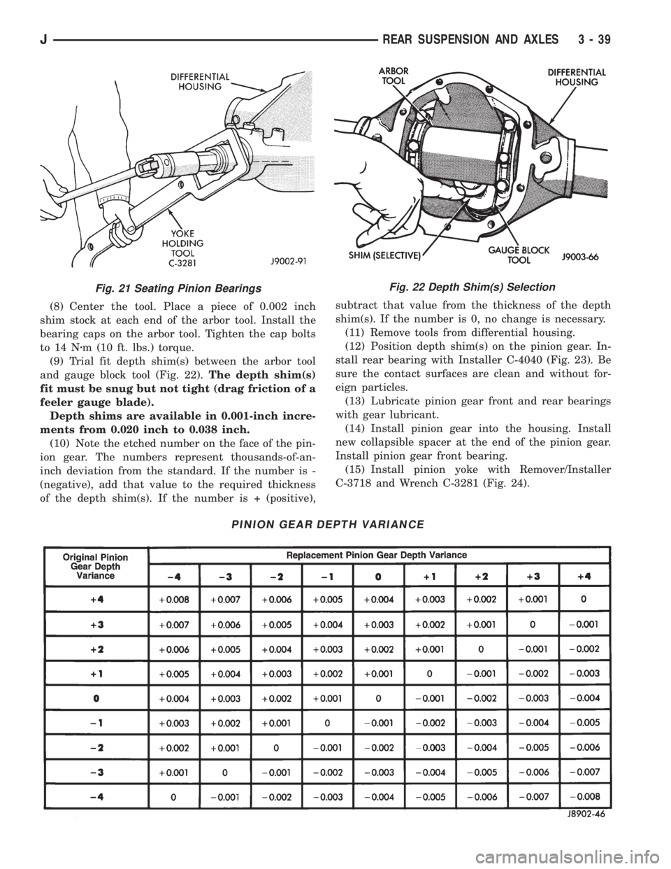
(8) Center the tool. Place a piece of 0.002 inch
shim stock at each end of the arbor tool. Install the
bearing caps on the arbor tool. Tighten the cap bolts
to 14 Nzm (10 ft. lbs.) torque.
(9) Trial fit depth shim(s) between the arbor tool
and gauge block tool (Fig. 22).The depth shim(s)
fit must be snug but not tight (drag friction of a
feeler gauge blade).
Depth shims are available in 0.001-inch incre-
ments from 0.020 inch to 0.038 inch.
(10) Note the etched number on the face of the pin-
ion gear. The numbers represent thousands-of-an-
inch deviation from the standard. If the number is -
(negative), add that value to the required thickness
of the depth shim(s). If the number is + (positive),subtract that value from the thickness of the depth
shim(s). If the number is 0, no change is necessary.
(11) Remove tools from differential housing.
(12) Position depth shim(s) on the pinion gear. In-
stall rear bearing with Installer C-4040 (Fig. 23). Be
sure the contact surfaces are clean and without for-
eign particles.
(13) Lubricate pinion gear front and rear bearings
with gear lubricant.
(14) Install pinion gear into the housing. Install
new collapsible spacer at the end of the pinion gear.
Install pinion gear front bearing.
(15) Install pinion yoke with Remover/Installer
C-3718 and Wrench C-3281 (Fig. 24).
Fig. 22 Depth Shim(s) Selection
PINION GEAR DEPTH VARIANCE
Fig. 21 Seating Pinion Bearings
JREAR SUSPENSION AND AXLES 3 - 39
Page 125 of 2198
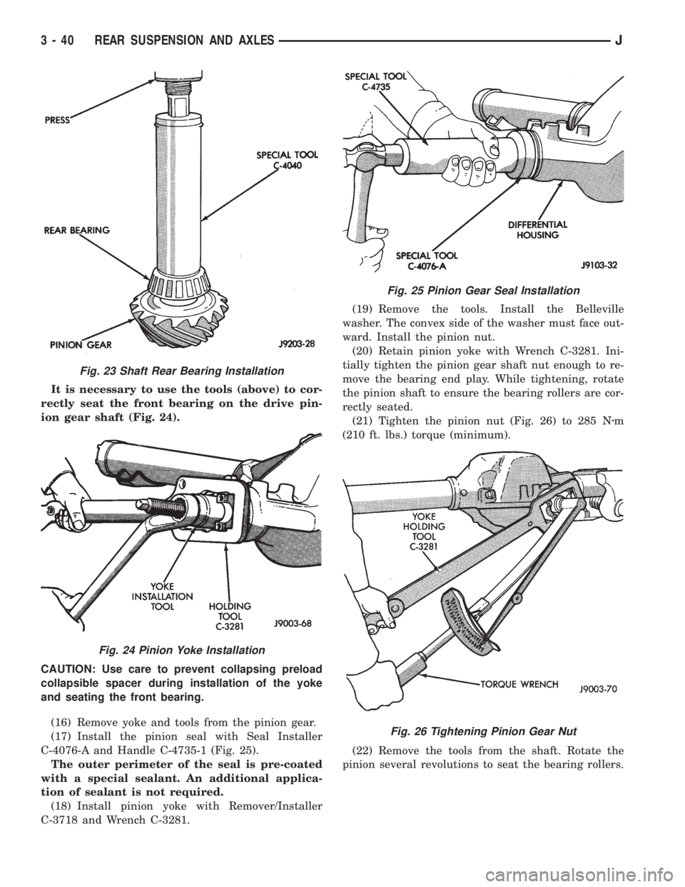
It is necessary to use the tools (above) to cor-
rectly seat the front bearing on the drive pin-
ion gear shaft (Fig. 24).
CAUTION: Use care to prevent collapsing preload
collapsible spacer during installation of the yoke
and seating the front bearing.
(16) Remove yoke and tools from the pinion gear.
(17) Install the pinion seal with Seal Installer
C-4076-A and Handle C-4735-1 (Fig. 25).
The outer perimeter of the seal is pre-coated
with a special sealant. An additional applica-
tion of sealant is not required.
(18) Install pinion yoke with Remover/Installer
C-3718 and Wrench C-3281.(19) Remove the tools. Install the Belleville
washer. The convex side of the washer must face out-
ward. Install the pinion nut.
(20) Retain pinion yoke with Wrench C-3281. Ini-
tially tighten the pinion gear shaft nut enough to re-
move the bearing end play. While tightening, rotate
the pinion shaft to ensure the bearing rollers are cor-
rectly seated.
(21) Tighten the pinion nut (Fig. 26) to 285 Nzm
(210 ft. lbs.) torque (minimum).
(22) Remove the tools from the shaft. Rotate the
pinion several revolutions to seat the bearing rollers.
Fig. 23 Shaft Rear Bearing Installation
Fig. 24 Pinion Yoke Installation
Fig. 25 Pinion Gear Seal Installation
Fig. 26 Tightening Pinion Gear Nut
3 - 40 REAR SUSPENSION AND AXLESJ
Page 126 of 2198
CAUTION: Never loosen pinion gear nut to decrease
pinion gear bearing preload torque and never ex-
ceed specified preload torque. If preload torque is
exceeded a new collapsible spacer must be in-
stalled. The torque sequence will have to be re-
peated.
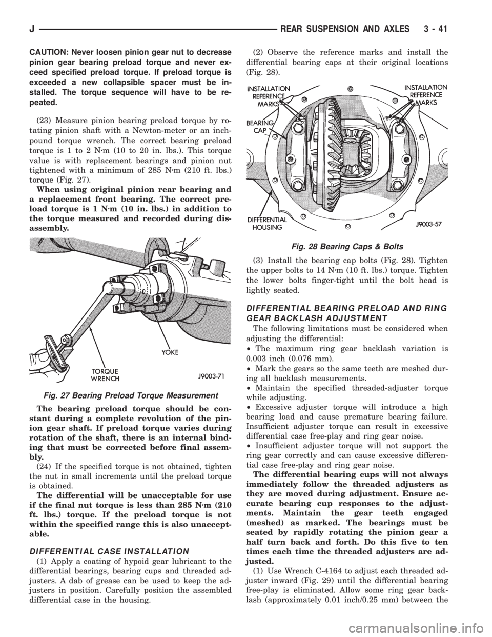
(23) Measure pinion bearing preload torque by ro-
tating pinion shaft with a Newton-meter or an inch-
pound torque wrench. The correct bearing preload
torque is 1 to 2 Nzm (10 to 20 in. lbs.). This torque
value is with replacement bearings and pinion nut
tightened with a minimum of 285 Nzm (210 ft. lbs.)
torque (Fig. 27).
When using original pinion rear bearing and
a replacement front bearing. The correct pre-
load torque is 1 Nzm (10 in. lbs.) in addition to
the torque measured and recorded during dis-
assembly.
The bearing preload torque should be con-
stant during a complete revolution of the pin-
ion gear shaft. If preload torque varies during
rotation of the shaft, there is an internal bind-
ing that must be corrected before final assem-
bly.
(24) If the specified torque is not obtained, tighten
the nut in small increments until the preload torque
is obtained.
The differential will be unacceptable for use
if the final nut torque is less than 285 Nzm (210
ft. lbs.) torque. If the preload torque is not
within the specified range this is also unaccept-
able.
DIFFERENTIAL CASE INSTALLATION
(1) Apply a coating of hypoid gear lubricant to the
differential bearings, bearing cups and threaded ad-
justers. A dab of grease can be used to keep the ad-
justers in position. Carefully position the assembled
differential case in the housing.(2) Observe the reference marks and install the
differential bearing caps at their original locations
(Fig. 28).
(3) Install the bearing cap bolts (Fig. 28). Tighten
the upper bolts to 14 Nzm (10 ft. lbs.) torque. Tighten
the lower bolts finger-tight until the bolt head is
lightly seated.
DIFFERENTIAL BEARING PRELOAD AND RING
GEAR BACKLASH ADJUSTMENT
The following limitations must be considered when
adjusting the differential:
²The maximum ring gear backlash variation is
0.003 inch (0.076 mm).
²Mark the gears so the same teeth are meshed dur-
ing all backlash measurements.
²Maintain the specified threaded-adjuster torque
while adjusting.
²Excessive adjuster torque will introduce a high
bearing load and cause premature bearing failure.
Insufficient adjuster torque can result in excessive
differential case free-play and ring gear noise.
²Insufficient adjuster torque will not support the
ring gear correctly and can cause excessive differen-
tial case free-play and ring gear noise.
The differential bearing cups will not always
immediately follow the threaded adjusters as
they are moved during adjustment. Ensure ac-
curate bearing cup responses to the adjust-
ments. Maintain the gear teeth engaged
(meshed) as marked. The bearings must be
seated by rapidly rotating the pinion gear a
half turn back and forth. Do this five to ten
times each time the threaded adjusters are ad-
justed.
(1) Use Wrench C-4164 to adjust each threaded ad-
juster inward (Fig. 29) until the differential bearing
free-play is eliminated. Allow some ring gear back-
lash (approximately 0.01 inch/0.25 mm) between the
Fig. 27 Bearing Preload Torque Measurement
Fig. 28 Bearing Caps & Bolts
JREAR SUSPENSION AND AXLES 3 - 41
Page 127 of 2198
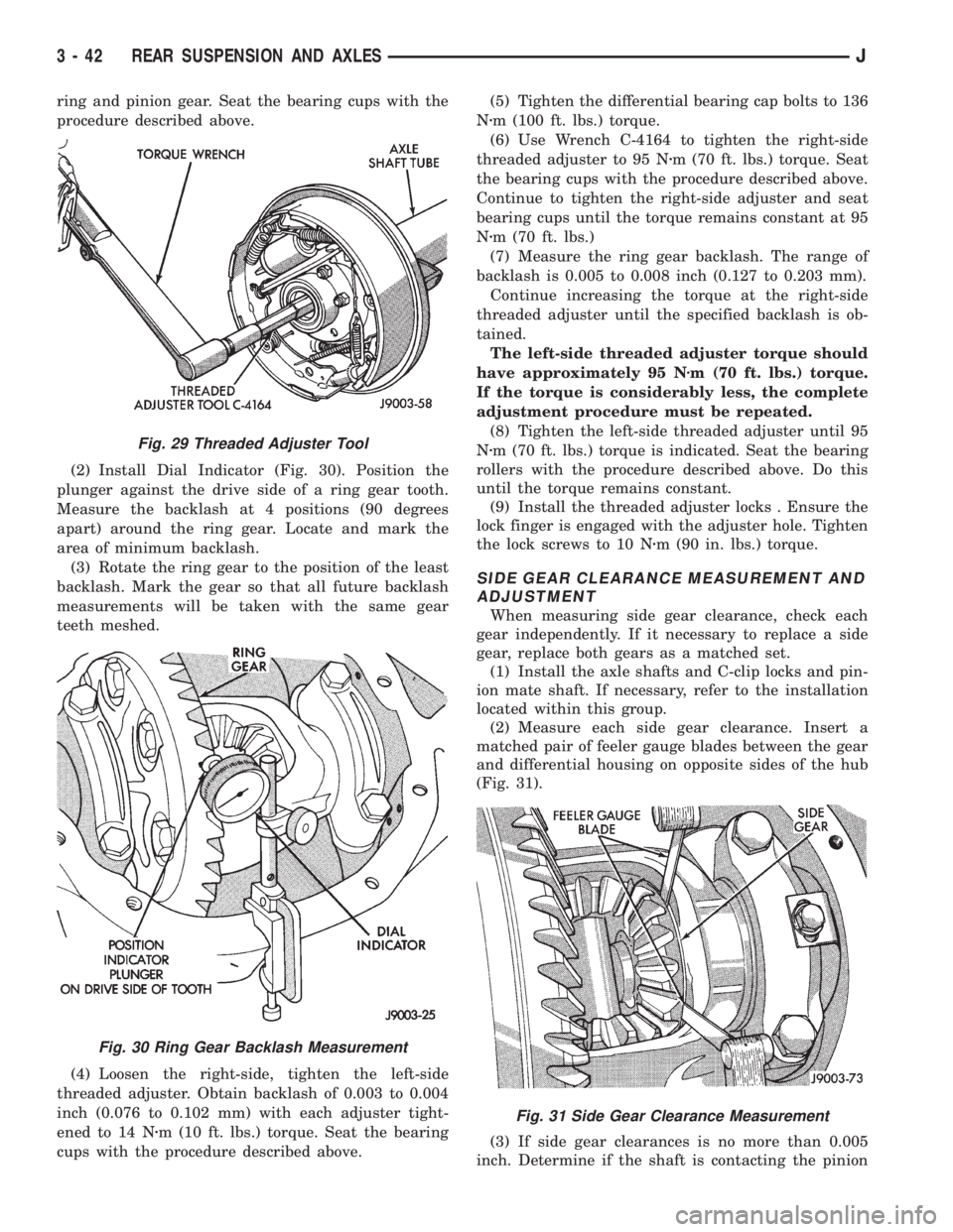
ring and pinion gear. Seat the bearing cups with the
procedure described above.
(2) Install Dial Indicator (Fig. 30). Position the
plunger against the drive side of a ring gear tooth.
Measure the backlash at 4 positions (90 degrees
apart) around the ring gear. Locate and mark the
area of minimum backlash.
(3) Rotate the ring gear to the position of the least
backlash. Mark the gear so that all future backlash
measurements will be taken with the same gear
teeth meshed.
(4) Loosen the right-side, tighten the left-side
threaded adjuster. Obtain backlash of 0.003 to 0.004
inch (0.076 to 0.102 mm) with each adjuster tight-
ened to 14 Nzm (10 ft. lbs.) torque. Seat the bearing
cups with the procedure described above.(5) Tighten the differential bearing cap bolts to 136
Nzm (100 ft. lbs.) torque.
(6) Use Wrench C-4164 to tighten the right-side
threaded adjuster to 95 Nzm (70 ft. lbs.) torque. Seat
the bearing cups with the procedure described above.
Continue to tighten the right-side adjuster and seat
bearing cups until the torque remains constant at 95
Nzm (70 ft. lbs.)
(7) Measure the ring gear backlash. The range of
backlash is 0.005 to 0.008 inch (0.127 to 0.203 mm).
Continue increasing the torque at the right-side
threaded adjuster until the specified backlash is ob-
tained.
The left-side threaded adjuster torque should
have approximately 95 Nzm (70 ft. lbs.) torque.
If the torque is considerably less, the complete
adjustment procedure must be repeated.
(8) Tighten the left-side threaded adjuster until 95
Nzm (70 ft. lbs.) torque is indicated. Seat the bearing
rollers with the procedure described above. Do this
until the torque remains constant.
(9) Install the threaded adjuster locks . Ensure the
lock finger is engaged with the adjuster hole. Tighten
the lock screws to 10 Nzm (90 in. lbs.) torque.
SIDE GEAR CLEARANCE MEASUREMENT AND
ADJUSTMENT
When measuring side gear clearance, check each
gear independently. If it necessary to replace a side
gear, replace both gears as a matched set.
(1) Install the axle shafts and C-clip locks and pin-
ion mate shaft. If necessary, refer to the installation
located within this group.
(2) Measure each side gear clearance. Insert a
matched pair of feeler gauge blades between the gear
and differential housing on opposite sides of the hub
(Fig. 31).
(3) If side gear clearances is no more than 0.005
inch. Determine if the shaft is contacting the pinion
Fig. 29 Threaded Adjuster Tool
Fig. 30 Ring Gear Backlash Measurement
Fig. 31 Side Gear Clearance Measurement
3 - 42 REAR SUSPENSION AND AXLESJ
Page 134 of 2198
(2) Inspect clutch pack plates for wear, scoring or
damage. Replace both clutch packs if any one compo-
nent in either pack is damaged.
(3) Inspect side and pinion gears. Replace any gear
that is worn, cracked, chipped or damaged.
(4) Inspect differential case and pinion shaft. Re-
place if worn or damaged.
PRESOAK PLATES AND DISC
Plates and dics with fiber coating (no groves or
lines) must be presoaked in Friction Modifier before
assembly. Soak plates and discs for a minimum of 20
minutes. Add remaining Friction Modifier to differen-
tial after assembly.
ASSEMBLY
(1) The clutch discs are replaceable as complete
sets only. If one clutch disc pack is damaged, both
packs must be replaced. Lubricate each component
with gear lubricant before assembly and installation.
(2) Assemble the clutch discs into packs and secure
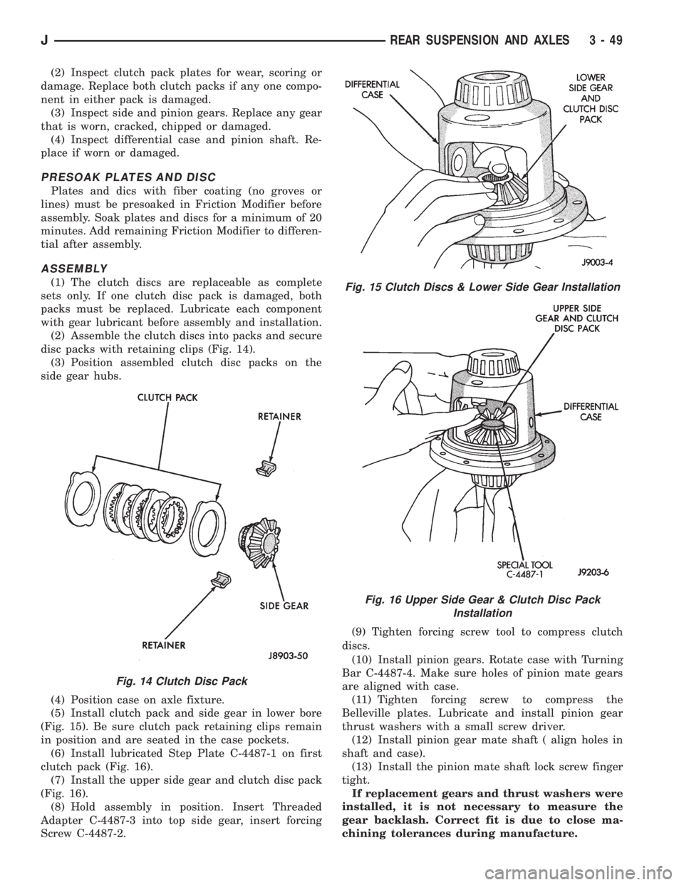
disc packs with retaining clips (Fig. 14).
(3) Position assembled clutch disc packs on the
side gear hubs.
(4) Position case on axle fixture.
(5) Install clutch pack and side gear in lower bore
(Fig. 15). Be sure clutch pack retaining clips remain
in position and are seated in the case pockets.
(6) Install lubricated Step Plate C-4487-1 on first
clutch pack (Fig. 16).
(7) Install the upper side gear and clutch disc pack
(Fig. 16).
(8) Hold assembly in position. Insert Threaded
Adapter C-4487-3 into top side gear, insert forcing
Screw C-4487-2.(9) Tighten forcing screw tool to compress clutch
discs.
(10) Install pinion gears. Rotate case with Turning
Bar C-4487-4. Make sure holes of pinion mate gears
are aligned with case.
(11) Tighten forcing screw to compress the
Belleville plates. Lubricate and install pinion gear
thrust washers with a small screw driver.
(12) Install pinion gear mate shaft ( align holes in
shaft and case).
(13) Install the pinion mate shaft lock screw finger
tight.
If replacement gears and thrust washers were
installed, it is not necessary to measure the
gear backlash. Correct fit is due to close ma-
chining tolerances during manufacture.
Fig. 14 Clutch Disc Pack
Fig. 15 Clutch Discs & Lower Side Gear Installation
Fig. 16 Upper Side Gear & Clutch Disc Pack
Installation
JREAR SUSPENSION AND AXLES 3 - 49
Page 145 of 2198
produce a condition similar to grab as the tire loses
and recovers traction.
Flat-spotted tires can cause vibration and wheel
tramp and generate shudder during brake operation.
A tire with internal damage such as a severe bruise
or ply separation can cause vibration and pull. The
pull will be magnified when braking.
DIAGNOSING PARKING BRAKE MALFUNCTIONS
Adjustment Mechanism
Parking brake adjustment is controlled by a ca-
ble tensioner mechanism. The cable tensioner,
once adjusted at the factory, will not need further
attention under normal circumstances. There are
only two instances when adjustment is required.
The first is when a new tensioner, or cables have
been installed. And the second, is when the ten-
sioner and cables are disconnected for access to
other brake components.
Parking Brake Switch And Warning Light Illumination
The parking brake switch on the lever, or foot
pedal, is in circuit with the red warning light. The
switch will illuminate the red light only when the
parking brakes are applied. If the light remains on
after parking brake release, the switch or wires are
faulty, or cable tensioner adjustment is incorrect.
If the red light comes on while the vehicle is in mo-
tion and brake pedal height decreases, a fault has oc-
curred in the front or rear brake hydraulic system.
Parking Brake problem Causes
In most cases, the actual cause of an improperly
functioning parking brake (too loose/too tight/wont
hold), can be traced to a drum brake component.
The leading cause of improper parking brake
operation, is excessive clearance between the
brakeshoes and the drum surface. Excessive
clearance is a result of: lining and/or drum
wear; oversize drums; or inoperative shoe ad-
juster components.
Excessive parking brake lever travel (sometimes de-
scribed as a loose lever or too loose condition), is the re-
sult of worn brakeshoes/drums, improper brakeshoe
adjustment, or incorrectly assembled brake parts.
A ``too loose'' condition can also be caused by inop-
erative brakeshoe adjusters. If the adjusters are mis-
assembled, they will not function. In addition, since
the adjuster mechanism only works during reverse
stops, it is important that complete stops be made.
The adjuster mechanism does not operate when roll-
ing stops are made in reverse. The vehicle must be
brought to a complete halt before the adjuster lever
will turn the adjuster screw.
A condition where the parking brakes do not hold, will
most probably be due to a wheel brake component.
Items to look for when diagnosing a parking brake
problem, are:
²rear brakeshoe wear or adjuster problem
²rear brake drum wear
²brake drums machined beyond allowable diameter
(oversize)
²parking brake front cable not secured to lever
²parking brake rear cable seized
²parking brake strut reversed
²parking brake strut not seated in both shoes
²parking brake lever not seated in secondary shoe
²parking brake lever or brakeshoe bind on support
plate
²brakeshoes reversed
²adjuster screws seized
²adjuster screws reversed
²holddown or return springs misassembled or lack
tension
²wheel cylinder pistons seized
Brake drums that are machined oversize are diffi-
cult to identify without inspection. If oversize drums
are suspected, diameter of the braking surface will
have to be checked with an accurate drum gauge.
Oversize drums will cause low brake pedal and lack
of parking brake holding ability.
Improper parking brake strut and lever installation
will result in unsatisfactory parking brake operation.
Intermixing the adjuster screws will cause drag, bind
and pull along with poor parking brake operation.
Parking brake adjustment and parts replacement pro-
cedures are described in the Parking Brake section.
MASTER CYLINDER/POWER BOOSTER TEST
(1) Start engine and check booster vacuum hose
connections. Hissing noise indicates vacuum leak.
Correct any vacuum leak before proceeding.
(2) Stop engine and shift transmission into Neu-
tral.
(3) Pump brake pedal until all vacuum reserve in
booster is depleted.
(4) Press and hold brake pedal under light foot
pressure.
(a) If pedal holds firm, proceed to step (5).
(b) If pedal does not hold firm and falls away,
master cylinder is faulty due to internal leakage.
Overhaul or replace cylinder.
(5) Start engine and note pedal action.
(a) If pedal falls away slightly under light foot
pressure then holds firm, proceed to step (6).
(b) If no pedal action is discernible, or hard pedal
is noted, power booster or vacuum check valve is
faulty. Install known good check valve and repeat
steps (2) through (5).
(6) Rebuild booster vacuum reserve as follows: Re-
lease brake pedal. Increase engine speed to 1500
rpm, close throttle and immediately turn off ignition.
5 - 8 SERVICE BRAKE DIAGNOSISJ
Page 153 of 2198
(2) Disconnect brake lines at master cylinder and
combination valve.
(3) Remove nuts attaching master cylinder to
booster studs.
(4) Remove master cylinder.
(5) Remove cylinder cover and drain fluid.
(6) If two-piece master cylinder reservoir requires
service, refer to reservoir replacement procedure in
this section.
MASTER CYLINDER INSTALLATION (NON-ABS)
(1) Bleed master cylinder on bench before installa-
tion. Refer to procedure in this section.
(2) If new two-piece master cylinder is being in-
stalled, remove plastic protective sleeve from primary
piston shank. Also check condition of seal at rear of
cylinder body. Reposition seal if dislodged. Replace
seal if cut, or torn.
(3) Clean cylinder mounting surface of brake booster.
Use shop towel wetted with brake cleaner for this pur-
pose. Dirt, grease, or similar materials will prevent
proper cylinder seating and could result in vacuum leak.
(4) Slide master cylinder onto brake booster studs.
(5) Install nuts attaching master cylinder to booster
studs. Tighten nuts to 25 Nzm (220 in. lbs.) torque.
(6) Connect brakelines to master cylinder and com-
bination valve (Figs. 1 and 2).
(7) Fill and bleed brake system.
COMBINATION VALVE REPLACEMENT (NON-ABS)
The combination valve is not a repairable compo-
nent. The valve is serviced as an assembly whenever
diagnosis indicates replacement is necessary.
(1) Remove air cleaner cover and hose for access to
valve, if necessary.
(2) Disconnect differential pressure switch wire at
combination valve. Do not pull switch wire to discon-
nect. Unsnap connecter lock tabs to remove.
(3) Disconnect brakelines at combination valve and
remove valve.
(4) Connect brakelines to replacement valve. Start
line fittings by hand to avoid cross threading.
Tighten fittings snug but not to required torque at
this time.
(5) Connect wire to pressure differential switch.
(6) Bleed brakes.
(7) Tighten brakeline fittings to 18-24 Nzm
(160-210 in. lbs.) torque after bleeding.
MASTER CYLINDER OVERHAUL (4-CYLINDER
MODELS)
CYLINDER DISASSEMBLY
(1) Examine cylinder cover seal. Discard seal if
torn or distorted.
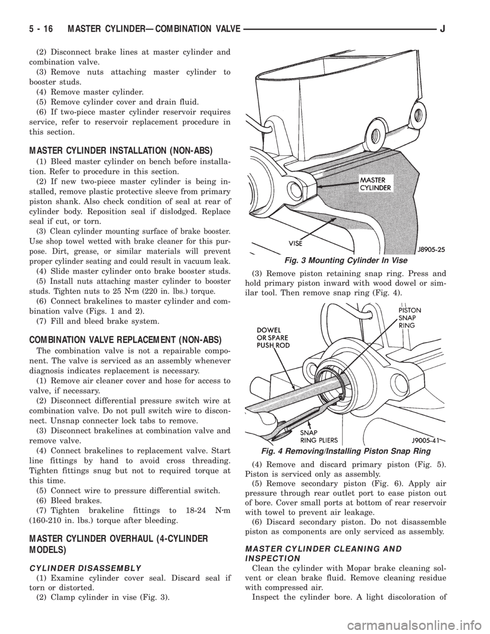
(2) Clamp cylinder in vise (Fig. 3).(3) Remove piston retaining snap ring. Press and
hold primary piston inward with wood dowel or sim-
ilar tool. Then remove snap ring (Fig. 4).
(4) Remove and discard primary piston (Fig. 5).
Piston is serviced only as assembly.
(5) Remove secondary piston (Fig. 6). Apply air
pressure through rear outlet port to ease piston out
of bore. Cover small ports at bottom of rear reservoir
with towel to prevent air leakage.
(6) Discard secondary piston. Do not disassemble
piston as components are only serviced as assembly.
MASTER CYLINDER CLEANING AND
INSPECTION
Clean the cylinder with Mopar brake cleaning sol-
vent or clean brake fluid. Remove cleaning residue
with compressed air.
Inspect the cylinder bore. A light discoloration of
Fig. 3 Mounting Cylinder In Vise
Fig. 4 Removing/Installing Piston Snap Ring
5 - 16 MASTER CYLINDERÐCOMBINATION VALVEJ
Page 155 of 2198
(5) Remove air cleaner housing from engine com-
partment.
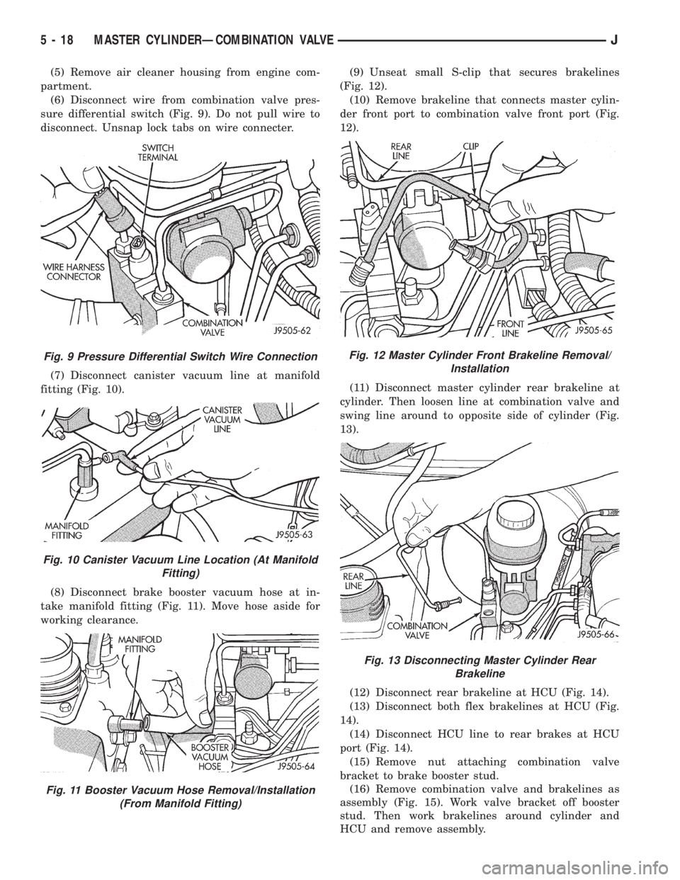
(6) Disconnect wire from combination valve pres-
sure differential switch (Fig. 9). Do not pull wire to
disconnect. Unsnap lock tabs on wire connecter.
(7) Disconnect canister vacuum line at manifold
fitting (Fig. 10).
(8) Disconnect brake booster vacuum hose at in-
take manifold fitting (Fig. 11). Move hose aside for
working clearance.(9) Unseat small S-clip that secures brakelines
(Fig. 12).
(10) Remove brakeline that connects master cylin-
der front port to combination valve front port (Fig.
12).
(11) Disconnect master cylinder rear brakeline at
cylinder. Then loosen line at combination valve and
swing line around to opposite side of cylinder (Fig.
13).
(12) Disconnect rear brakeline at HCU (Fig. 14).
(13) Disconnect both flex brakelines at HCU (Fig.
14).
(14) Disconnect HCU line to rear brakes at HCU
port (Fig. 14).
(15) Remove nut attaching combination valve
bracket to brake booster stud.
(16) Remove combination valve and brakelines as
assembly (Fig. 15). Work valve bracket off booster
stud. Then work brakelines around cylinder and
HCU and remove assembly.
Fig. 9 Pressure Differential Switch Wire Connection
Fig. 10 Canister Vacuum Line Location (At Manifold
Fitting)
Fig. 11 Booster Vacuum Hose Removal/Installation
(From Manifold Fitting)
Fig. 12 Master Cylinder Front Brakeline Removal/
Installation
Fig. 13 Disconnecting Master Cylinder Rear
Brakeline
5 - 18 MASTER CYLINDERÐCOMBINATION VALVEJ