1995 JEEP CHEROKEE seat
[x] Cancel search: seatPage 67 of 2198
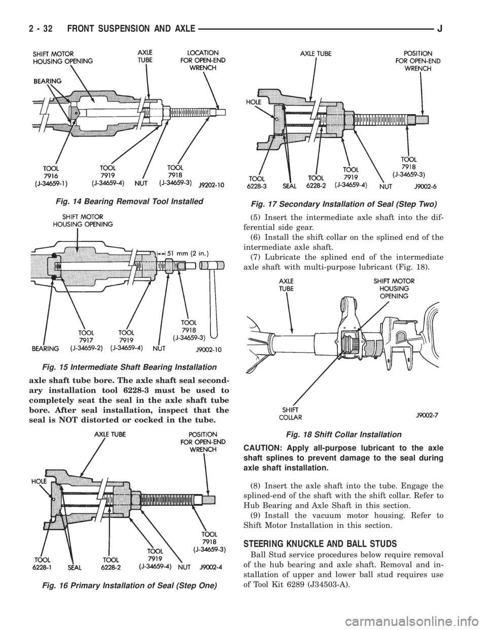
axle shaft tube bore. The axle shaft seal second-
ary installation tool 6228-3 must be used to
completely seat the seal in the axle shaft tube
bore. After seal installation, inspect that the
seal is NOT distorted or cocked in the tube.(5) Insert the intermediate axle shaft into the dif-
ferential side gear.
(6) Install the shift collar on the splined end of the
intermediate axle shaft.
(7) Lubricate the splined end of the intermediate
axle shaft with multi-purpose lubricant (Fig. 18).
CAUTION: Apply all-purpose lubricant to the axle
shaft splines to prevent damage to the seal during
axle shaft installation.
(8) Insert the axle shaft into the tube. Engage the
splined-end of the shaft with the shift collar. Refer to
Hub Bearing and Axle Shaft in this section.
(9) Install the vacuum motor housing. Refer to
Shift Motor Installation in this section.
STEERING KNUCKLE AND BALL STUDS
Ball Stud service procedures below require removal
of the hub bearing and axle shaft. Removal and in-
stallation of upper and lower ball stud requires use
of Tool Kit 6289 (J34503-A).
Fig. 14 Bearing Removal Tool Installed
Fig. 15 Intermediate Shaft Bearing Installation
Fig. 16 Primary Installation of Seal (Step One)
Fig. 17 Secondary Installation of Seal (Step Two)
Fig. 18 Shift Collar Installation
2 - 32 FRONT SUSPENSION AND AXLEJ
Page 69 of 2198

(4) Install the Hub Bearing and Axle Shaft accord-
ing to the installation procedure.
(5) Reconnect the tie-rod or drag link end onto the
steering knuckle arm. Install the ABS sensor wire
and bracket to the knuckle, refer to Group 5 Brakes.
AXLE BUSHING REPLACEMENT
Refer to Axle Bushing Replacement in the Front
Suspension section.
DIFFERENTIAL REMOVAL
To service the differential the axle assembly and
axle shafts must be removed. Refer to the removal
procedures in this Group.
(1) Note the installation reference letters stamped
on the bearing caps and housing machined sealing
surface (Fig. 22).
(2) Remove the differential bearing caps.
(3) Position Spreader W-129-B with the tool dowel
pins seated in the locating holes (Fig. 23). Install the
holddown clamps and tighten the tool turnbuckle fin-
ger-tight.
(4) Install a pilot stud at the left side of the differ-
ential housing. Attach Dial Indicator to housing pilot
stud. Load the indicator plunger against the opposite
side of the housing (Fig. 23) and zero the indicator.CAUTION:Do not spread over 0.38 mm (0.015 in). If
the housing is over-separated, it could be distorted
or damaged.
(5) Separate the housing enough to remove the
case from the housing. Measure the distance with the
dial indicator (Fig. 23).
(6) Remove the dial indicator.
(7) Pry the differential case loose from the housing.
To prevent damage, pivot on housing with the end of
the pry bar against spreader (Fig. 24).
Fig. 21 Lower Ball Stud Remove/Install
Fig. 22 Bearing Cap Identification
2 - 34 FRONT SUSPENSION AND AXLEJ
Page 73 of 2198
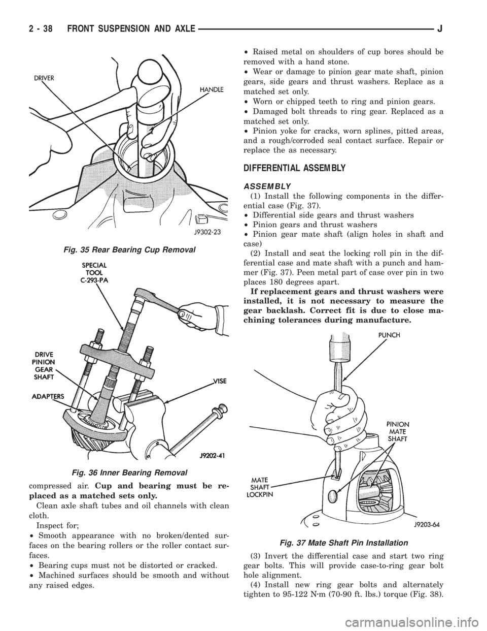
compressed air.Cup and bearing must be re-
placed as a matched sets only.
Clean axle shaft tubes and oil channels with clean
cloth.
Inspect for;
²Smooth appearance with no broken/dented sur-
faces on the bearing rollers or the roller contact sur-
faces.
²Bearing cups must not be distorted or cracked.
²Machined surfaces should be smooth and without
any raised edges.²Raised metal on shoulders of cup bores should be
removed with a hand stone.
²Wear or damage to pinion gear mate shaft, pinion
gears, side gears and thrust washers. Replace as a
matched set only.
²Worn or chipped teeth to ring and pinion gears.
²Damaged bolt threads to ring gear. Replaced as a
matched set only.
²Pinion yoke for cracks, worn splines, pitted areas,
and a rough/corroded seal contact surface. Repair or
replace the as necessary.
DIFFERENTIAL ASSEMBLY
ASSEMBLY
(1) Install the following components in the differ-
ential case (Fig. 37).
²Differential side gears and thrust washers
²Pinion gears and thrust washers
²Pinion gear mate shaft (align holes in shaft and
case)
(2) Install and seat the locking roll pin in the dif-
ferential case and mate shaft with a punch and ham-
mer (Fig. 37). Peen metal part of case over pin in two
places 180 degrees apart.
If replacement gears and thrust washers were
installed, it is not necessary to measure the
gear backlash. Correct fit is due to close ma-
chining tolerances during manufacture.
(3) Invert the differential case and start two ring
gear bolts. This will provide case-to-ring gear bolt
hole alignment.
(4) Install new ring gear bolts and alternately
tighten to 95-122 Nzm (70-90 ft. lbs.) torque (Fig. 38).
Fig. 35 Rear Bearing Cup Removal
Fig. 36 Inner Bearing Removal
Fig. 37 Mate Shaft Pin Installation
2 - 38 FRONT SUSPENSION AND AXLEJ
Page 76 of 2198
²Axle housing or differential case is replaced
²Pinion select shim pack is unknown
²Ring and pinion gears are replaced
Measurements are done with pinion cups and pin-
ion bearings installed in housing. Take measure-
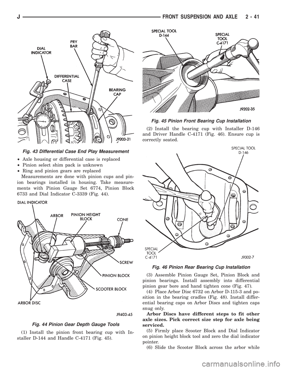
ments with Pinion Gauge Set 6774, Pinion Block
6733 and Dial Indicator C-3339 (Fig. 44).
(1) Install the pinion front bearing cup with In-
staller D-144 and Handle C-4171 (Fig. 45).(2) Install the bearing cup with Installer D-146
and Driver Handle C-4171 (Fig. 46). Ensure cup is
correctly seated.
(3) Assemble Pinion Gauge Set, Pinion Block and
pinion bearings. Install assembly into differential
pinion gear bore and hand tighten cone (Fig. 47).
(4) Place Arbor Disc 6732 on Arbor D-115-3 and po-
sition in the bearing cradles (Fig. 48). Install differ-
ential bearing caps on Arbor Discs and tighten caps
snug only.
Arbor Discs have different steps to fit other
axle sizes. Pick correct size step for axle being
serviced.
(5) Firmly place Scooter Block and Dial Indicator
on pinion height block tool and zero the dial indicator
pointer.
(6) Slide the Scooter Block across the arbor while
Fig. 43 Differential Case End Play Measurement
Fig. 44 Pinion Gear Depth Gauge Tools
Fig. 45 Pinion Front Bearing Cup Installation
Fig. 46 Pinion Rear Bearing Cup Installation
JFRONT SUSPENSION AND AXLE 2 - 41
Page 77 of 2198
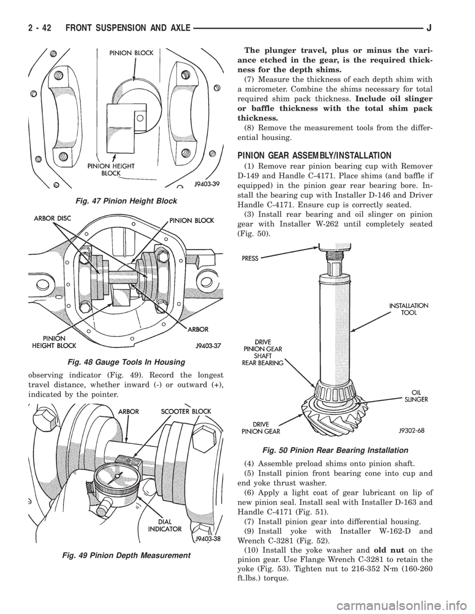
observing indicator (Fig. 49). Record the longest
travel distance, whether inward (-) or outward (+),
indicated by the pointer.The plunger travel, plus or minus the vari-
ance etched in the gear, is the required thick-
ness for the depth shims.
(7) Measure the thickness of each depth shim with
a micrometer. Combine the shims necessary for total
required shim pack thickness.Include oil slinger
or baffle thickness with the total shim pack
thickness.
(8) Remove the measurement tools from the differ-
ential housing.
PINION GEAR ASSEMBLY/INSTALLATION
(1) Remove rear pinion bearing cup with Remover
D-149 and Handle C-4171. Place shims (and baffle if
equipped) in the pinion gear rear bearing bore. In-
stall the bearing cup with Installer D-146 and Driver
Handle C-4171. Ensure cup is correctly seated.
(3) Install rear bearing and oil slinger on pinion
gear with Installer W-262 until completely seated
(Fig. 50).
(4) Assemble preload shims onto pinion shaft.
(5) Install pinion front bearing cone into cup and
end yoke thrust washer.
(6) Apply a light coat of gear lubricant on lip of
new pinion seal. Install seal with Installer D-163 and
Handle C-4171 (Fig. 51).
(7) Install pinion gear into differential housing.
(9) Install yoke with Installer W-162-D and
Wrench C-3281 (Fig. 52).
(10) Install the yoke washer andold nuton the
pinion gear. Use Flange Wrench C-3281 to retain the
yoke (Fig. 53). Tighten nut to 216-352 Nzm (160-260
ft.lbs.) torque.
Fig. 47 Pinion Height Block
Fig. 48 Gauge Tools In Housing
Fig. 49 Pinion Depth Measurement
Fig. 50 Pinion Rear Bearing Installation
2 - 42 FRONT SUSPENSION AND AXLEJ
Page 79 of 2198
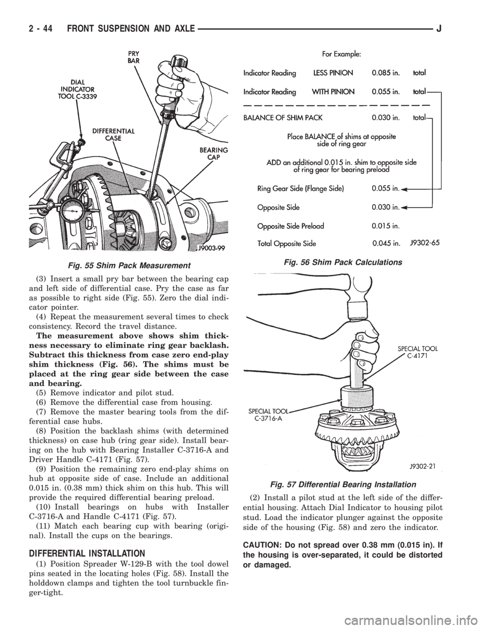
(3) Insert a small pry bar between the bearing cap
and left side of differential case. Pry the case as far
as possible to right side (Fig. 55). Zero the dial indi-
cator pointer.
(4) Repeat the measurement several times to check
consistency. Record the travel distance.
The measurement above shows shim thick-
ness necessary to eliminate ring gear backlash.
Subtract this thickness from case zero end-play
shim thickness (Fig. 56). The shims must be
placed at the ring gear side between the case
and bearing.
(5) Remove indicator and pilot stud.
(6) Remove the differential case from housing.
(7) Remove the master bearing tools from the dif-
ferential case hubs.
(8) Position the backlash shims (with determined
thickness) on case hub (ring gear side). Install bear-
ing on the hub with Bearing Installer C-3716-A and
Driver Handle C-4171 (Fig. 57).
(9) Position the remaining zero end-play shims on
hub at opposite side of case. Include an additional
0.015 in. (0.38 mm) thick shim on this hub. This will
provide the required differential bearing preload.
(10) Install bearings on hubs with Installer
C-3716-A and Handle C-4171 (Fig. 57).
(11) Match each bearing cup with bearing (origi-
nal). Install the cups on the bearings.
DIFFERENTIAL INSTALLATION
(1) Position Spreader W-129-B with the tool dowel
pins seated in the locating holes (Fig. 58). Install the
holddown clamps and tighten the tool turnbuckle fin-
ger-tight.(2) Install a pilot stud at the left side of the differ-
ential housing. Attach Dial Indicator to housing pilot
stud. Load the indicator plunger against the opposite
side of the housing (Fig. 58) and zero the indicator.
CAUTION: Do not spread over 0.38 mm (0.015 in). If
the housing is over-separated, it could be distorted
or damaged.
Fig. 55 Shim Pack MeasurementFig. 56 Shim Pack Calculations
Fig. 57 Differential Bearing Installation
2 - 44 FRONT SUSPENSION AND AXLEJ
Page 80 of 2198
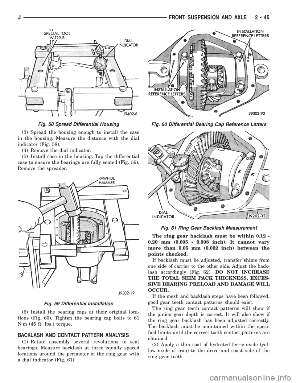
(3) Spread the housing enough to install the case
in the housing. Measure the distance with the dial
indicator (Fig. 58).
(4) Remove the dial indicator.
(5) Install case in the housing. Tap the differential
case to ensure the bearings are fully seated (Fig. 59).
Remove the spreader.
(6) Install the bearing caps at their original loca-
tions (Fig. 60). Tighten the bearing cap bolts to 61
Nzm (45 ft. lbs.) torque.
BACKLASH AND CONTACT PATTERN ANALYSIS
(1) Rotate assembly several revolutions to seat
bearings. Measure backlash at three equally spaced
locations around the perimeter of the ring gear with
a dial indicator (Fig. 61).The ring gear backlash must be within 0.12 -
0.20 mm (0.005 - 0.008 inch). It cannot vary
more than 0.05 mm (0.002 inch) between the
points checked.
If backlash must be adjusted, transfer shims from
one side of carrier to the other side. Adjust the back-
lash accordingly (Fig. 62).DO NOT INCREASE
THE TOTAL SHIM PACK THICKNESS, EXCES-
SIVE BEARING PRELOAD AND DAMAGE WILL
OCCUR.
If the mesh and backlash steps have been followed,
good gear teeth contact patterns should exist.
The ring gear teeth contact patterns will show if
the pinion gear depth is correct. It will also show if
the ring gear backlash has been adjusted correctly.
The backlash must be maintained within the speci-
fied limits until the correct tooth contact patterns are
obtained.
(2) Apply a thin coat of hydrated ferric oxide (yel-
low oxide of iron) to the drive and coast side of the
ring gear teeth.
Fig. 58 Spread Differential Housing
Fig. 59 Differential Installation
Fig. 60 Differential Bearing Cap Reference Letters
Fig. 61 Ring Gear Backlash Measurement
JFRONT SUSPENSION AND AXLE 2 - 45
Page 92 of 2198
SHOCK ABSORBER
REMOVAL
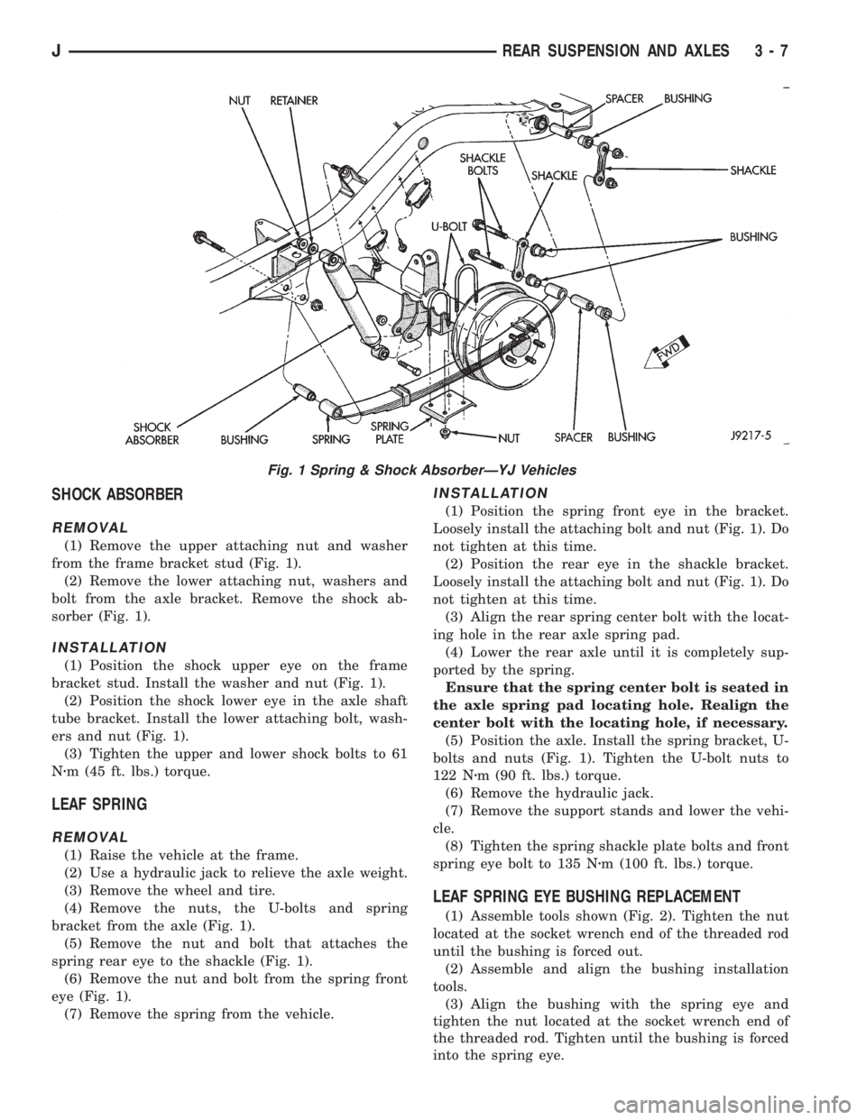
(1) Remove the upper attaching nut and washer
from the frame bracket stud (Fig. 1).
(2) Remove the lower attaching nut, washers and
bolt from the axle bracket. Remove the shock ab-
sorber (Fig. 1).
INSTALLATION
(1) Position the shock upper eye on the frame
bracket stud. Install the washer and nut (Fig. 1).
(2) Position the shock lower eye in the axle shaft
tube bracket. Install the lower attaching bolt, wash-
ers and nut (Fig. 1).
(3) Tighten the upper and lower shock bolts to 61
Nzm (45 ft. lbs.) torque.
LEAF SPRING
REMOVAL
(1) Raise the vehicle at the frame.
(2) Use a hydraulic jack to relieve the axle weight.
(3) Remove the wheel and tire.
(4) Remove the nuts, the U-bolts and spring
bracket from the axle (Fig. 1).
(5) Remove the nut and bolt that attaches the
spring rear eye to the shackle (Fig. 1).
(6) Remove the nut and bolt from the spring front
eye (Fig. 1).
(7) Remove the spring from the vehicle.
INSTALLATION
(1) Position the spring front eye in the bracket.
Loosely install the attaching bolt and nut (Fig. 1). Do
not tighten at this time.
(2) Position the rear eye in the shackle bracket.
Loosely install the attaching bolt and nut (Fig. 1). Do
not tighten at this time.
(3) Align the rear spring center bolt with the locat-
ing hole in the rear axle spring pad.
(4) Lower the rear axle until it is completely sup-
ported by the spring.
Ensure that the spring center bolt is seated in
the axle spring pad locating hole. Realign the
center bolt with the locating hole, if necessary.
(5) Position the axle. Install the spring bracket, U-
bolts and nuts (Fig. 1). Tighten the U-bolt nuts to
122 Nzm (90 ft. lbs.) torque.
(6) Remove the hydraulic jack.
(7) Remove the support stands and lower the vehi-
cle.
(8) Tighten the spring shackle plate bolts and front
spring eye bolt to 135 Nzm (100 ft. lbs.) torque.
LEAF SPRING EYE BUSHING REPLACEMENT
(1) Assemble tools shown (Fig. 2). Tighten the nut
located at the socket wrench end of the threaded rod
until the bushing is forced out.
(2) Assemble and align the bushing installation
tools.
(3) Align the bushing with the spring eye and
tighten the nut located at the socket wrench end of
the threaded rod. Tighten until the bushing is forced
into the spring eye.
Fig. 1 Spring & Shock AbsorberÐYJ Vehicles
JREAR SUSPENSION AND AXLES 3 - 7