1995 JEEP CHEROKEE seat
[x] Cancel search: seatPage 200 of 2198
(12) Parking brake switch can be serviced at this
time, if necessary.
PARKING BRAKE LEVER INSTALLATION (XJ WITH
MINI CONSOLE)
(1) Assemble lever and tensioner components (Figs.
4 and 5). Be sure E-clip is fully seated in pin (Fig. 4).
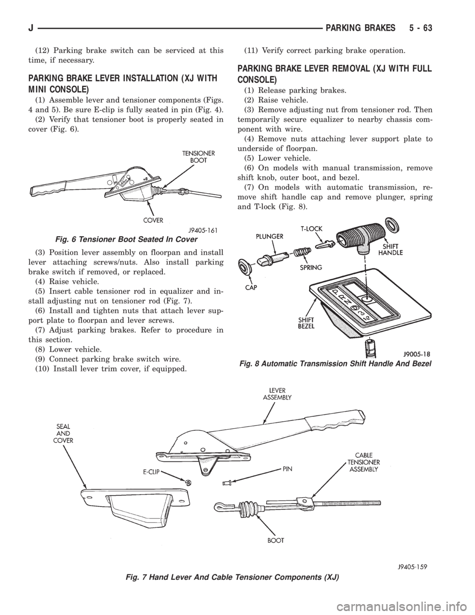
(2) Verify that tensioner boot is properly seated in
cover (Fig. 6).
(3) Position lever assembly on floorpan and install
lever attaching screws/nuts. Also install parking
brake switch if removed, or replaced.
(4) Raise vehicle.
(5) Insert cable tensioner rod in equalizer and in-
stall adjusting nut on tensioner rod (Fig. 7).
(6) Install and tighten nuts that attach lever sup-
port plate to floorpan and lever screws.
(7) Adjust parking brakes. Refer to procedure in
this section.
(8) Lower vehicle.
(9) Connect parking brake switch wire.
(10) Install lever trim cover, if equipped.(11) Verify correct parking brake operation.
PARKING BRAKE LEVER REMOVAL (XJ WITH FULL
CONSOLE)
(1) Release parking brakes.
(2) Raise vehicle.
(3) Remove adjusting nut from tensioner rod. Then
temporarily secure equalizer to nearby chassis com-
ponent with wire.
(4) Remove nuts attaching lever support plate to
underside of floorpan.
(5) Lower vehicle.
(6) On models with manual transmission, remove
shift knob, outer boot, and bezel.
(7) On models with automatic transmission, re-
move shift handle cap and remove plunger, spring
and T-lock (Fig. 8).
Fig. 7 Hand Lever And Cable Tensioner Components (XJ)
Fig. 6 Tensioner Boot Seated In Cover
Fig. 8 Automatic Transmission Shift Handle And Bezel
JPARKING BRAKES 5 - 63
Page 201 of 2198
(8) Remove shift handle by pulling upward sharply
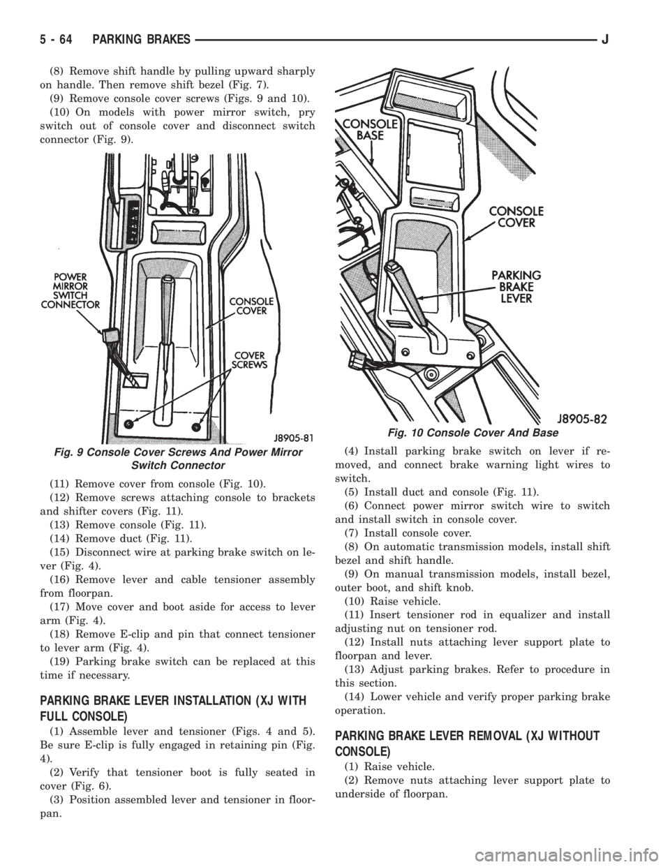
on handle. Then remove shift bezel (Fig. 7).
(9) Remove console cover screws (Figs. 9 and 10).
(10) On models with power mirror switch, pry
switch out of console cover and disconnect switch
connector (Fig. 9).
(11) Remove cover from console (Fig. 10).
(12) Remove screws attaching console to brackets
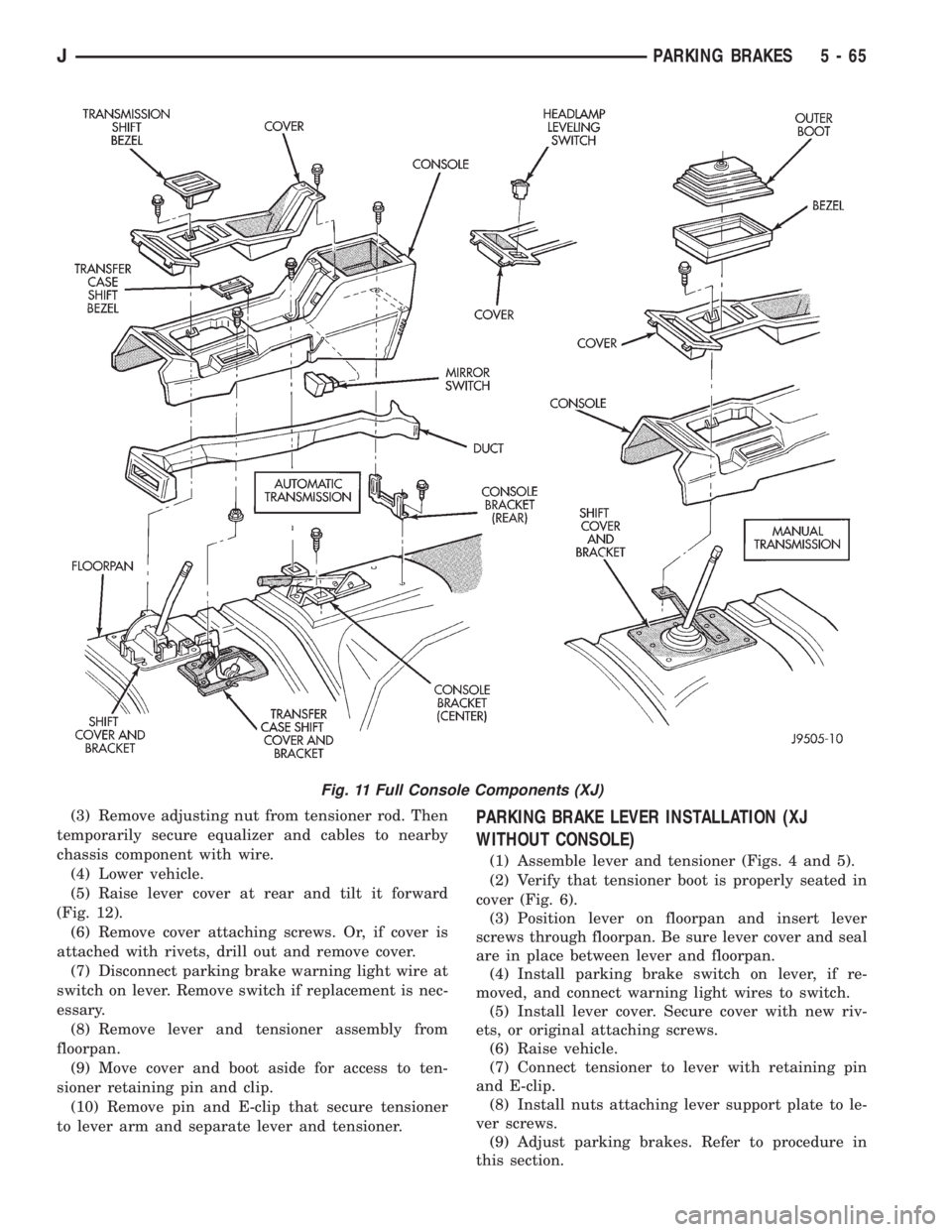
and shifter covers (Fig. 11).
(13) Remove console (Fig. 11).
(14) Remove duct (Fig. 11).
(15) Disconnect wire at parking brake switch on le-
ver (Fig. 4).
(16) Remove lever and cable tensioner assembly
from floorpan.
(17) Move cover and boot aside for access to lever
arm (Fig. 4).
(18) Remove E-clip and pin that connect tensioner
to lever arm (Fig. 4).
(19) Parking brake switch can be replaced at this
time if necessary.
PARKING BRAKE LEVER INSTALLATION (XJ WITH
FULL CONSOLE)
(1) Assemble lever and tensioner (Figs. 4 and 5).
Be sure E-clip is fully engaged in retaining pin (Fig.
4).
(2) Verify that tensioner boot is fully seated in
cover (Fig. 6).
(3) Position assembled lever and tensioner in floor-
pan.(4) Install parking brake switch on lever if re-
moved, and connect brake warning light wires to
switch.
(5) Install duct and console (Fig. 11).
(6) Connect power mirror switch wire to switch
and install switch in console cover.
(7) Install console cover.
(8) On automatic transmission models, install shift
bezel and shift handle.
(9) On manual transmission models, install bezel,
outer boot, and shift knob.
(10) Raise vehicle.
(11) Insert tensioner rod in equalizer and install
adjusting nut on tensioner rod.
(12) Install nuts attaching lever support plate to
floorpan and lever.
(13) Adjust parking brakes. Refer to procedure in
this section.
(14) Lower vehicle and verify proper parking brake
operation.PARKING BRAKE LEVER REMOVAL (XJ WITHOUT
CONSOLE)
(1) Raise vehicle.
(2) Remove nuts attaching lever support plate to
underside of floorpan.
Fig. 9 Console Cover Screws And Power Mirror
Switch Connector
Fig. 10 Console Cover And Base
5 - 64 PARKING BRAKESJ
Page 202 of 2198
(3) Remove adjusting nut from tensioner rod. Then
temporarily secure equalizer and cables to nearby
chassis component with wire.
(4) Lower vehicle.
(5) Raise lever cover at rear and tilt it forward
(Fig. 12).
(6) Remove cover attaching screws. Or, if cover is
attached with rivets, drill out and remove cover.
(7) Disconnect parking brake warning light wire at
switch on lever. Remove switch if replacement is nec-
essary.
(8) Remove lever and tensioner assembly from
floorpan.
(9) Move cover and boot aside for access to ten-
sioner retaining pin and clip.
(10) Remove pin and E-clip that secure tensioner
to lever arm and separate lever and tensioner.PARKING BRAKE LEVER INSTALLATION (XJ
WITHOUT CONSOLE)
(1) Assemble lever and tensioner (Figs. 4 and 5).
(2) Verify that tensioner boot is properly seated in
cover (Fig. 6).
(3) Position lever on floorpan and insert lever
screws through floorpan. Be sure lever cover and seal
are in place between lever and floorpan.
(4) Install parking brake switch on lever, if re-
moved, and connect warning light wires to switch.
(5) Install lever cover. Secure cover with new riv-
ets, or original attaching screws.
(6) Raise vehicle.
(7) Connect tensioner to lever with retaining pin
and E-clip.
(8) Install nuts attaching lever support plate to le-
ver screws.
(9) Adjust parking brakes. Refer to procedure in
this section.
Fig. 11 Full Console Components (XJ)
JPARKING BRAKES 5 - 65
Page 203 of 2198
PARKING BRAKE CABLE TENSIONER
REPLACEMENT (XJ)
(1) Raise vehicle.
(2) Remove adjuster nut from tensioner rod. Secure
equalizer and cables to nearby chassis component
with wire.
(3) Remove nuts attaching lever assembly to sup-
port plate and floorpan.
(4) Lower vehicle.
(5) Remove console components and lever assembly
cover.
(6) Remove lever and tensioner assembly.
(7) Move cover and boot for access to tensioner re-
taining pin.
(8) Remove E-clip and pin that attach tensioner to
lever arm (Fig. 4).
(9) Remove tensioner from cover.
(10) Transfer boot to new tensioner if necessary.
(11) Attach tensioner to lever arm with pin and E-
clip.
(12) Verify that E-clip is fully engaged in pin (Fig.
4).
(13) Align cover and seal on lever flange.
(14) Verify that tensioner boot is seated in cover
(Fig. 6).
(15) Install assembled lever and tensioner in floor-
pan.
(16) Install necessary console components.
(17) Adjust parking brakes as described in this sec-
tion.
PARKING BRAKE PEDAL REMOVAL (YJ)
(1) Raise vehicle.
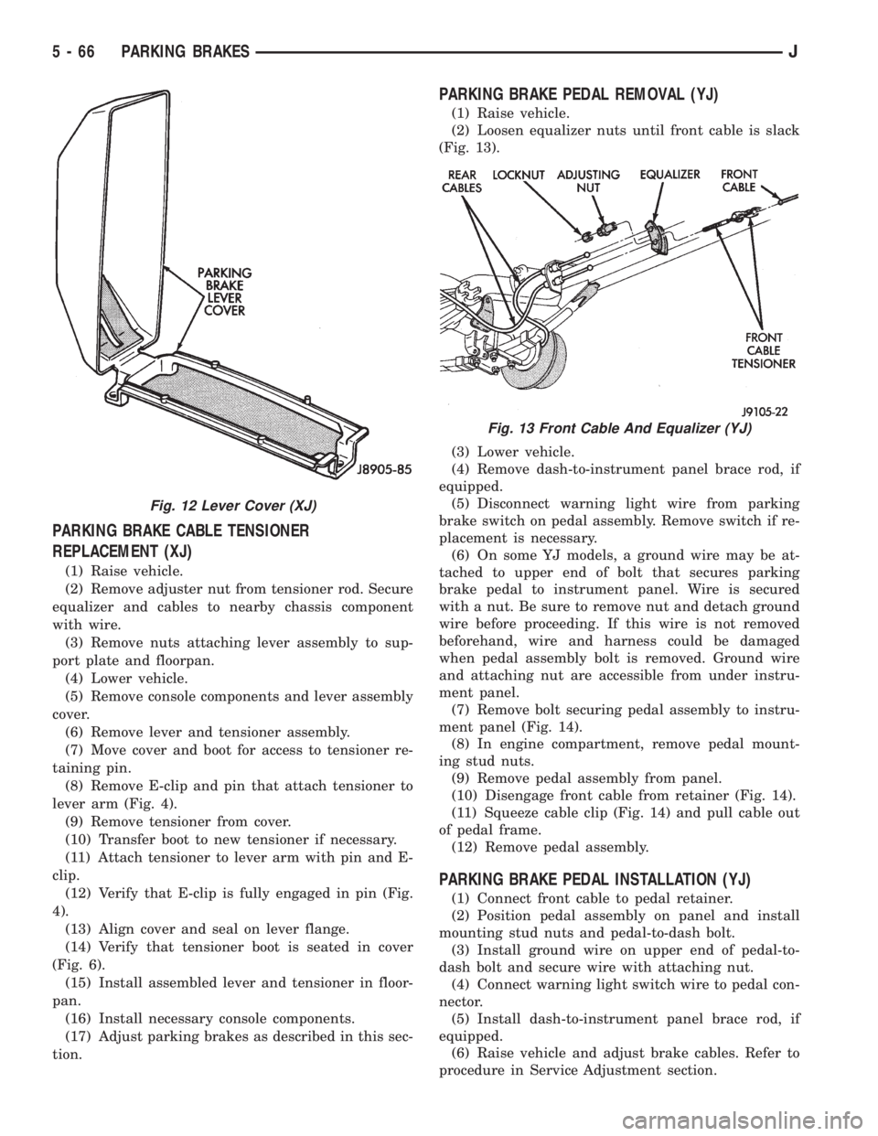
(2) Loosen equalizer nuts until front cable is slack
(Fig. 13).
(3) Lower vehicle.
(4) Remove dash-to-instrument panel brace rod, if
equipped.
(5) Disconnect warning light wire from parking
brake switch on pedal assembly. Remove switch if re-
placement is necessary.
(6) On some YJ models, a ground wire may be at-
tached to upper end of bolt that secures parking
brake pedal to instrument panel. Wire is secured
with a nut. Be sure to remove nut and detach ground
wire before proceeding. If this wire is not removed
beforehand, wire and harness could be damaged
when pedal assembly bolt is removed. Ground wire
and attaching nut are accessible from under instru-
ment panel.
(7) Remove bolt securing pedal assembly to instru-
ment panel (Fig. 14).
(8) In engine compartment, remove pedal mount-
ing stud nuts.
(9) Remove pedal assembly from panel.
(10) Disengage front cable from retainer (Fig. 14).
(11) Squeeze cable clip (Fig. 14) and pull cable out
of pedal frame.
(12) Remove pedal assembly.
PARKING BRAKE PEDAL INSTALLATION (YJ)
(1) Connect front cable to pedal retainer.
(2) Position pedal assembly on panel and install
mounting stud nuts and pedal-to-dash bolt.
(3) Install ground wire on upper end of pedal-to-
dash bolt and secure wire with attaching nut.
(4) Connect warning light switch wire to pedal con-
nector.
(5) Install dash-to-instrument panel brace rod, if
equipped.
(6) Raise vehicle and adjust brake cables. Refer to
procedure in Service Adjustment section.
Fig. 12 Lever Cover (XJ)
Fig. 13 Front Cable And Equalizer (YJ)
5 - 66 PARKING BRAKESJ
Page 204 of 2198
PARKING BRAKE REAR CABLE REPLACEMENT (XJ)
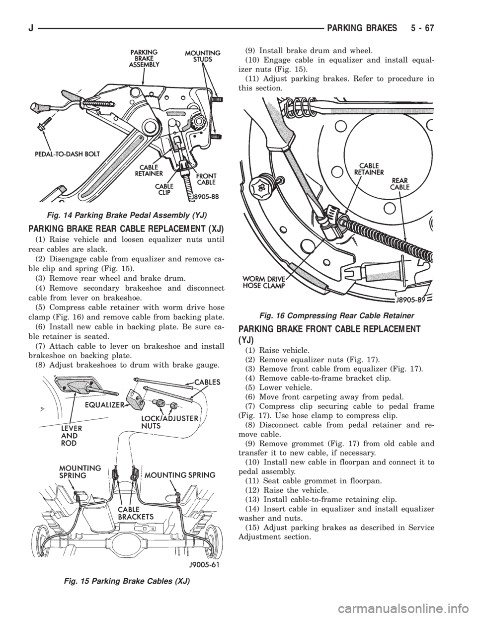
(1) Raise vehicle and loosen equalizer nuts until
rear cables are slack.
(2) Disengage cable from equalizer and remove ca-
ble clip and spring (Fig. 15).
(3) Remove rear wheel and brake drum.
(4) Remove secondary brakeshoe and disconnect
cable from lever on brakeshoe.
(5) Compress cable retainer with worm drive hose
clamp (Fig. 16) and remove cable from backing plate.
(6) Install new cable in backing plate. Be sure ca-
ble retainer is seated.
(7) Attach cable to lever on brakeshoe and install
brakeshoe on backing plate.
(8) Adjust brakeshoes to drum with brake gauge.(9) Install brake drum and wheel.
(10) Engage cable in equalizer and install equal-
izer nuts (Fig. 15).
(11) Adjust parking brakes. Refer to procedure in
this section.
PARKING BRAKE FRONT CABLE REPLACEMENT
(YJ)
(1) Raise vehicle.
(2) Remove equalizer nuts (Fig. 17).
(3) Remove front cable from equalizer (Fig. 17).
(4) Remove cable-to-frame bracket clip.
(5) Lower vehicle.
(6) Move front carpeting away from pedal.
(7) Compress clip securing cable to pedal frame
(Fig. 17). Use hose clamp to compress clip.
(8) Disconnect cable from pedal retainer and re-
move cable.
(9) Remove grommet (Fig. 17) from old cable and
transfer it to new cable, if necessary.
(10) Install new cable in floorpan and connect it to
pedal assembly.
(11) Seat cable grommet in floorpan.
(12) Raise the vehicle.
(13) Install cable-to-frame retaining clip.
(14) Insert cable in equalizer and install equalizer
washer and nuts.
(15) Adjust parking brakes as described in Service
Adjustment section.
Fig. 14 Parking Brake Pedal Assembly (YJ)
Fig. 15 Parking Brake Cables (XJ)
Fig. 16 Compressing Rear Cable Retainer
JPARKING BRAKES 5 - 67
Page 210 of 2198
CLUTCH DIAGNOSIS
INDEX
page page
Clutch Contamination....................... 3
Clutch Cover and Disc Runout................ 3
Clutch Housing Misalignment................. 4
Clutch Misalignment........................ 3Flywheel Runout........................... 3
General Diagnosis Information................ 3
Inspection and Diagnosis Charts............... 4
Installation Methods and Parts Usage........... 4
GENERAL DIAGNOSIS INFORMATION
Unless the cause of a clutch problem is obvious, ac-
curate problem diagnosis will usually require a road
test to confirm a problem. Component inspection will
then be required to determine the actual problem
cause.
During a road test, drive the vehicle at normal
speeds. Shift the transmission through all gear
ranges and observe clutch action. If chatter, grab,
slip, or improper release is experienced, remove and
inspect the clutch components. However, if the prob-
lem is noise or hard shifting, further diagnosis may
be needed as the transmission or another driveline
component may be at fault. Careful observation dur-
ing the test will help narrow the problem area.
CLUTCH CONTAMINATION
Fluid contamination is a frequent cause of clutch
malfunctions. Oil, water, or clutch fluid on the clutch
disc and pressure plate surfaces will cause chatter,
slip and grab.
During inspection, note if any components are con-
taminated with oil, hydraulic fluid, or water/road
splash.
Oil contamination indicates a leak at either the
rear main seal or transmission input shaft. Oil leak-
age produces a residue of oil on the housing interior
and on the clutch cover and flywheel. Heat buildup
caused by slippage between the cover, disc and fly-
wheel, can sometimes bake the oil residue onto the
components. The glaze-like residue ranges in color
from amber to black.
Road splash contamination means dirt/water is en-
tering the clutch housing due to loose bolts, housing
cracks, or through hydraulic line openings. Driving
through deep water puddles can force water/road
splash into the housing through such openings.
Clutch fluid leaks are usually from damaged slave
cylinder push rod seals. This type of leak can only be
confirmed by visual inspection.
CLUTCH MISALIGNMENT
Clutch components must be in proper alignment
with the crankshaft and transmission input shaft.Misalignment caused by excessive runout or warpage
of any clutch component will cause grab, chatter and
improper clutch release.
FLYWHEEL RUNOUT
Check flywheel runout whenever misalignment is
suspected. Flywheel runout should not exceed 0.08
mm (0.003 in.). Measure runout at the outer edge of
the flywheel face with a dial indicator. Mount the in-
dicator on a stud installed in place of one of the fly-
wheel bolts.
Common causes of runout are:
²heat warpage
²improper machining
²incorrect bolt tightening
²improper seating on crankshaft flange shoulder
²foreign material on crankshaft flange
Flywheel machining is not recommended. The fly-
wheel clutch surface is machined to a unique contour
and machining will negate this feature. However, mi-
nor flywheel scoring can be cleaned up by hand with
180 grit emery, or with surface grinding equipment.
Remove only enough material to reduce scoring (ap-
proximately 0.001 - 0.003 in.). Heavy stock removal
isnot recommended.Replace the flywheel if scor-
ing is severe and deeper than 0.076 mm (0.003 in.).
Excessive stock removal can result in flywheel crack-
ing or warpage after installation; it can also weaken
the flywheel and interfere with proper clutch release.
Clean the crankshaft flange before mounting the
flywheel. Dirt and grease on the flange surface may
cock the flywheel causing excessive runout. Use new
bolts when remounting a flywheel and secure the
bolts with Mopar Lock And Seal. Tighten flywheel
bolts to specified torque only. Overtightening can dis-
tort the flywheel hub causing runout.
CLUTCH COVER AND DISC RUNOUT
Check the clutch disc before installation. Axial
(face) runout of anewdisc should not exceed 0.50
mm (0.020 in.). Measure runout about 6 mm (1/4 in.)
from the outer edge of the disc facing. Obtain an-
other disc if runout is excessive.
Check condition of the clutch before installation. A
warped cover or diaphragm spring will cause grab
and incomplete release or engagement. Be careful
JCLUTCH DIAGNOSIS 6 - 3
Page 211 of 2198
when handling the cover and disc. Impact can distort
the cover, diaphragm spring, release fingers and the
hub of the clutch disc.
Use an alignment tool when positioning the disc on
the flywheel. The tool prevents accidental misalign-
ment which could result in cover distortion and disc
damage.
A frequent cause of clutch cover distortion (and
consequent misalignment) is improper bolt tighten-
ing. To avoid warping the cover, the bolts must tight-
ened alternately (diagonal pattern) and evenly (2-3
threads at a time) to specified torque.
CLUTCH HOUSING MISALIGNMENT
Clutch housing alignment is important to proper
clutch operation. The housing maintains alignment
between the crankshaft and transmission input
shaft. Misalignment can cause clutch noise, hard
shifting, incomplete release and chatter. It can also
result in premature wear of the pilot bearing, cover
release fingers and clutch disc. In severe cases, mis-
alignment can also cause premature wear of the
transmission input shaft and front bearing.
Housing misalignment is generally caused by incor-
rect seating on the engine or transmission, loose
housing bolts, missing alignment dowels, or housing
damage. Infrequently, misalignment may also be
caused by housing mounting surfaces that are not
completely parallel. Misalignment can be corrected
with shims.
INSTALLATION METHODS AND PARTS USAGE
Distortion of clutch components during installation
and the use of non-standard components are addi-
tional causes of clutch malfunction.Improper clutch cover bolt tightening can distort
the cover. The usual result is clutch grab, chatter
and rapid wear. Tighten the cover bolts as described
in Clutch Service section.
An improperly seated flywheel and/or clutch hous-
ing are additional causes of clutch failure. Improper
seating will produce misalignment and additional
clutch problems.
The use of non-standard or low quality parts will
also lead to problems and wear. Use recommended
factory quality parts to avoid comebacks.
A cocked pilot bearing is another cause of clutch
noise, drag, and hard shifting, and rapid bearing
wear. Always use an alignment tool to install a new
bearing. This practice helps avoid cocking the bear-
ing during installation.
INSPECTION AND DIAGNOSIS CHARTS
The clutch inspection chart (Fig. 1) outlines items
to be checked before and during clutch installation.
Use the chart as a check list to help avoid overlook-
ing potential problem sources during service opera-
tions.
The diagnosis charts describe common clutch prob-
lems, causes and correction. Fault conditions are
listed at the top of each chart. Conditions, causes and
corrective action are outlined in the indicated col-
umns.
The charts are provided as a convenient reference
when diagnosing faulty clutch operation.
6 - 4 CLUTCH DIAGNOSISJ
Page 219 of 2198
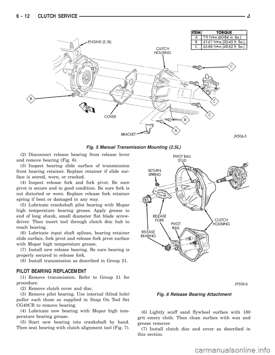
(2) Disconnect release bearing from release lever
and remove bearing (Fig. 6).
(3) Inspect bearing slide surface of transmission
front bearing retainer. Replace retainer if slide sur-
face is scored, worn, or cracked.
(4) Inspect release fork and fork pivot. Be sure
pivot is secure and in good condition. Be sure fork is
not distorted or worn. Replace release fork retainer
spring if bent or damaged in any way.
(5) Lubricate crankshaft pilot bearing with Mopar
high temperature bearing grease. Apply grease to
end of long shank, small diameter flat blade screw-
driver. Then insert tool through clutch disc hub to
reach bearing.
(6) Lubricate input shaft splines, bearing retainer
slide surface, fork pivot and release fork pivot surface
with Mopar high temperature grease.
(7) Install new release bearing. Be sure bearing is
properly secured to release fork.
(8) Install transmission as described in Group 21.
PILOT BEARING REPLACEMENT
(1) Remove transmission. Refer to Group 21 for
procedure.
(2) Remove clutch cover and disc.
(3) Remove pilot bearing. Use internal (blind hole)
puller such those as supplied in Snap On Tool Set
CG40CB to remove bearing.
(4) Lubricate new bearing with Mopar high tem-
perature bearing grease.
(5) Start new bearing into crankshaft by hand.
Then seat bearing with clutch alignment tool (Fig. 7).(6) Lightly scuff sand flywheel surface with 180
grit emery cloth. Then clean surface with wax and
grease remover.
(7) Install clutch disc and cover as described in
this section.
Fig. 5 Manual Transmission Mounting (2.5L)
Fig. 6 Release Bearing Attachment
6 - 12 CLUTCH SERVICEJ