1995 JEEP CHEROKEE seat
[x] Cancel search: seatPage 502 of 2198
SERVICE PROCEDURES
POWER SEAT SWITCH REMOVE/INSTALL
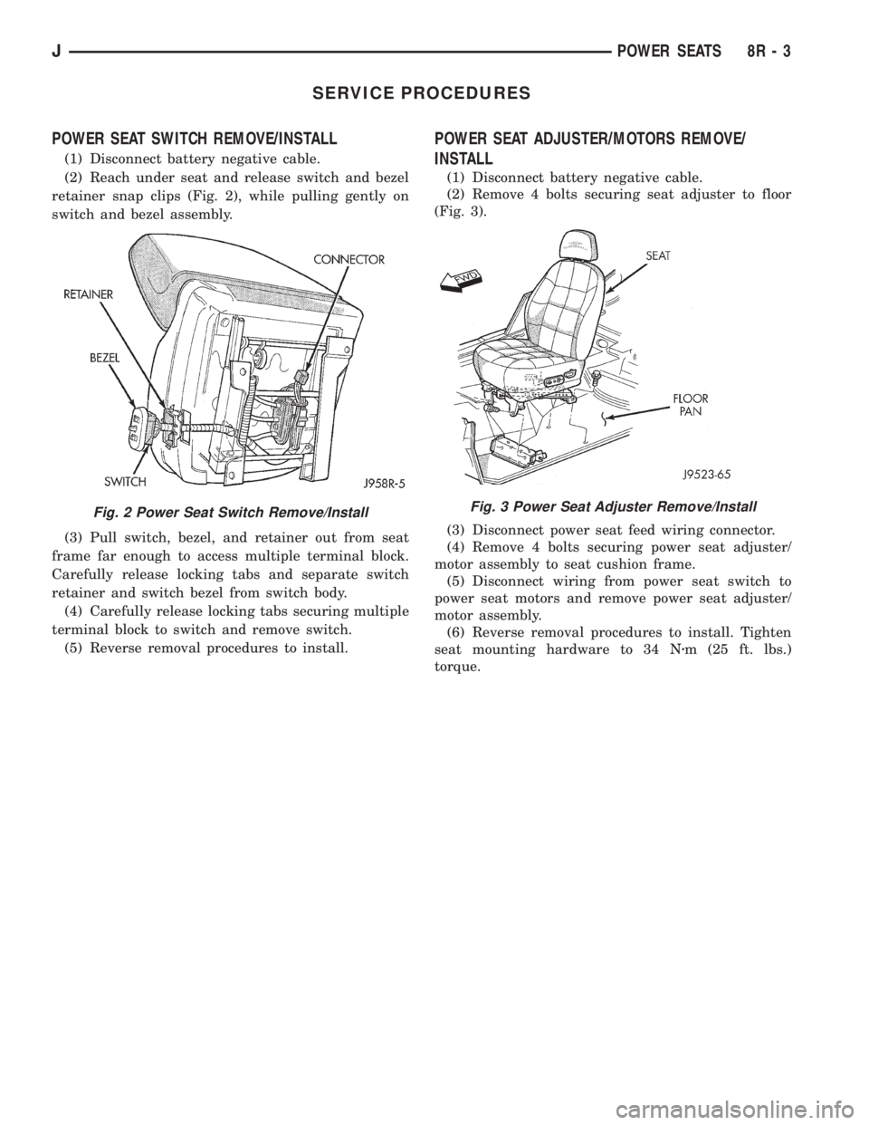
(1) Disconnect battery negative cable.
(2) Reach under seat and release switch and bezel
retainer snap clips (Fig. 2), while pulling gently on
switch and bezel assembly.
(3) Pull switch, bezel, and retainer out from seat
frame far enough to access multiple terminal block.
Carefully release locking tabs and separate switch
retainer and switch bezel from switch body.
(4) Carefully release locking tabs securing multiple
terminal block to switch and remove switch.
(5) Reverse removal procedures to install.
POWER SEAT ADJUSTER/MOTORS REMOVE/
INSTALL
(1) Disconnect battery negative cable.
(2) Remove 4 bolts securing seat adjuster to floor
(Fig. 3).
(3) Disconnect power seat feed wiring connector.
(4) Remove 4 bolts securing power seat adjuster/
motor assembly to seat cushion frame.
(5) Disconnect wiring from power seat switch to
power seat motors and remove power seat adjuster/
motor assembly.
(6) Reverse removal procedures to install. Tighten
seat mounting hardware to 34 Nzm (25 ft. lbs.)
torque.
Fig. 2 Power Seat Switch Remove/InstallFig. 3 Power Seat Adjuster Remove/Install
JPOWER SEATS 8R - 3
Page 518 of 2198
CHIME/BUZZER WARNING SYSTEMS
CONTENTS
page page
DIAGNOSIS............................. 2
GENERAL INFORMATION.................. 1SERVICE PROCEDURES................... 4
GENERAL INFORMATION
This group covers the buzzer warning system,
which is standard equipment on XJ (Cherokee)/YJ
(Wrangler) models. The system provides an audible
warning to the driver when it monitors the following
conditions:
²key is in ignition switch with the driver's door
open
²head or park lamps are on with driver's door open
(XJ only)
²driver's seat belt is not buckled with ignition
switch in ON position.
Following are general descriptions of the major
components in the buzzer warning system. Refer to
Group 8W - Wiring Diagrams for complete circuit de-
scriptions and diagrams.
BUZZER MODULE
The buzzer module is located in the fuseblock mod-
ule under the left end of the instrument panel. It re-
ceives battery voltage at all times from (fuse 15 - XJ,
fuse 3 - YJ) the fuseblock module. It also receives a
second battery feed (fuse 17 - XJ, fuse 9 - YJ) when
the ignition switch is in the ON or START position.
Other inputs to the module include the driver's door
jamb switch, the driver's seat belt switch, the ignition
key-in switch, and the headlamp switch (XJ only). The
only output of the module is a timed 4 to 8 second feed
to the seat belt reminder lamp in the message center of
the instrument cluster. The timer function begins after
the ignition switch is turned to the ON position.
The buzzer module can not be repaired. If faulty, it
must be replaced.
DRIVER'S DOOR JAMB SWITCH
The driver's door jamb switch is mounted to the
driver's door hinge pillar. The switch closes a path to
ground for the buzzer module through the key-in
switch or headlamp switch (XJ only) when the driv-
er's door is opened, and opens when the driver's door
is closed. This switch can not be repaired. If faulty, it
must be replaced.
IGNITION KEY-IN SWITCH
XJ MODELS
The key-in switch is integral to the ignition switch,
which is mounted on the right side of the steering col-
umn. It closes a path to ground for the buzzer module
when the ignition key is inserted in the ignition lock cyl-
inder and the driver's door jamb switch is closed (door
open). The switch opens when the key is removed from
the ignition lock cylinder. This switch can not be re-
paired. If faulty, the entire ignition switch must be re-
placed. Refer to Group 8D - Ignition Systems for service
procedures.
YJ MODELS
The key-in switch is mounted within the steering col-
umn in the lock cylinder housing. It closes a path to
ground for the buzzer module when the ignition key is
inserted in the ignition lock cylinder and the driver's
door jamb switch is closed (door open). The switch opens
when the key is removed from the ignition lock cylinder.
This switch is available for service replacement. Refer
to Group 19 - Steering for service procedures.
HEADLAMP SWITCH (XJ ONLY)
The headlamp switch is located in the instrument
panel. It closes a path to ground for the buzzer module
when the park or headlamps are on and the driver's
door jamb switch is closed (door open). The switch opens
the ground path when the park and headlamps are
turned off. The headlamp switch can not be repaired. If
faulty, it must be replaced. Refer to Group 8E - Instru-
ment Panel and Gauges for service procedures.
DRIVER'S SEAT BELT SWITCH
The driver's seat belt switch is integral to the driv-
er's seat belt buckle-half assembly. The switch is nor-
mally closed, providing a ground path to the buzzer
module. When the tip-half of the seat belt is inserted
into the seat belt buckle, the switch opens the buzzer
module ground path. The seat belt switch can not be
repaired. If faulty, the entire driver's seat belt buck-
le-half must be replaced. Refer to Group 23 - Body
Components for service procedures.
JCHIME/BUZZER WARNING SYSTEMS 8U - 1
Page 520 of 2198
YJ MODELS
(1) Unplug steering column connector from instru-
ment panel wiring. Open driver's door. Check for con-
tinuity between cavity E (black/light blue wire) in
instrument panel half of steering column connector
and a good ground. There should be continuity. If
OK, go to next step. If not OK, repair circuit to driv-
er's door jamb switch as required.
(2) Insert ignition key in ignition lock cylinder.
Check for continuity between cavities E (pink wire)
and F (black wire) in steering column half of connec-
tor. There should be continuity until key is removed.
If OK, go to next step. If not OK, repair steering col-
umn wiring or replace key-in switch as required.
(3) Check for continuity between cavity F (light
blue wire) in instrument panel half of steering col-
umn connector and cavity for terminal 6 of buzzer
module in buzzer module connector. There should be
continuity. If not OK, repair circuit from switch to
buzzer module as required.
HEADLAMP SWITCH (XJ ONLY)
(1) Remove headlamp switch from instrument
panel (refer to Group 8E - Instrument Panel and
Gauges for procedure). Unplug headlamp switch con-
nector. Open driver's door. Check for continuity be-
tween headlamp switch connector cavity with light
blue wire and a good ground. There should be conti-
nuity until driver's door is closed. If OK, go to next
step. If not OK, repair circuit from headlamp switch
to driver's door jamb switch as required.
(2) Check for continuity between headlamp switch
connector cavity with pink/light blue wire and cavity
for terminal 6 of buzzer module in buzzer module
connector. There should be continuity. If OK, go to
next step. If not OK, repair circuit from headlamp
switch to buzzer module as required.
(3) Check continuity between headlamp switch ter-
minal for connector cavity with pink/light blue wire
and terminal for cavity with light blue wire. There
should be no continuity with switch in off position,
and there should be continuity with switch in park
lamps or headlamps on position. If not OK, replace
headlamp switch.
DRIVER'S SEAT BELT SWITCH
(1) Unplug seat belt switch connector on floor un-
der driver's seat riser near seat belt anchor. Check
for continuity between two cavities of seat belt half of
connector. There should be continuity with seat belt
unbuckled, and no continuity with seat belt buckled.
If OK, go to next step. If not OK, replace seat belt
buckle-half assembly.
(2) Check for continuity between cavity with black
wire in harness half of seat belt switch connector and
a good ground. There should be continuity. If OK, go
to next step. If not OK, repair circuit to ground as re-
quired.
(3) Check for continuity between cavity with light
green wire in harness half of seat belt switch connec-
tor and cavity for terminal 4 of buzzer module con-
nector. There should be continuity. If not OK, repair
circuit from seat belt switch connector to buzzer mod-
ule as required.
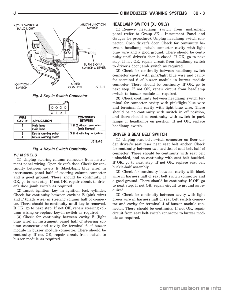
Fig. 3 Key-In Switch Connector
Fig. 4 Key-In Switch Continuity
JCHIME/BUZZER WARNING SYSTEMS 8U - 3
Page 521 of 2198
SERVICE PROCEDURES
Service procedures for components of the buzzer
system can be found in the appropriate group as fol-
lows:
²driver's door jamb switch - refer to Group 8L -
Lamps
²ignition key-in switch (XJ) - refer to Group 8D -
Ignition Systems²ignition key-in switch (YJ) - refer to Group 19 -
Steering
²headlamp switch - refer to Group 8E - Instrument
Panel and Gauges
²driver's seat belt switch - refer to Group 23 - Body
Components.
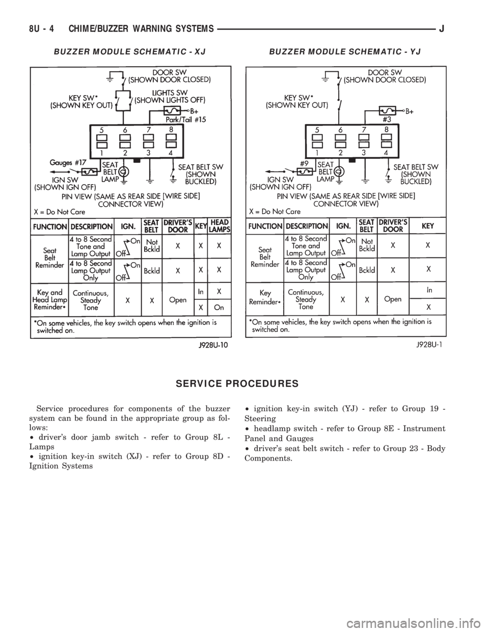
BUZZER MODULE SCHEMATIC - XJBUZZER MODULE SCHEMATIC - YJ
8U - 4 CHIME/BUZZER WARNING SYSTEMSJ
Page 525 of 2198
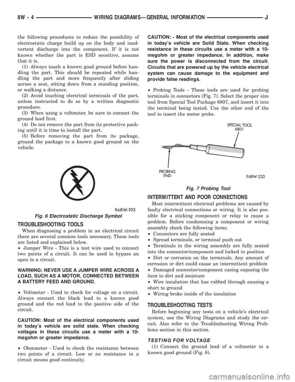
the following procedures to reduce the possibility of
electrostatic charge build up on the body and inad-
vertent discharge into the component. If it is not
known whether the part is ESD sensitive, assume
that it is.
(1) Always touch a known good ground before han-
dling the part. This should be repeated while han-
dling the part and more frequently after sliding
across a seat, sitting down from a standing position,
or walking a distance.
(2) Avoid touching electrical terminals of the part,
unless instructed to do so by a written diagnostic
procedure.
(3) When using a voltmeter, be sure to connect the
ground lead first.
(4) Do not remove the part from its protective pack-
ing until it is time to install the part.
(5) Before removing the part from its package,
ground the package to a known good ground on the
vehicle.
TROUBLESHOOTING TOOLS
When diagnosing a problem in an electrical circuit
there are several common tools necessary. These tools
are listed and explained below.
²Jumper Wire - This is a test wire used to connect
two points of a circuit. It can be used to bypass an
open in a circuit.
WARNING: NEVER USE A JUMPER WIRE ACROSS A
LOAD, SUCH AS A MOTOR, CONNECTED BETWEEN
A BATTERY FEED AND GROUND.
²Voltmeter - Used to check for voltage on a circuit.
Always connect the black lead to a known good
ground and the red lead to the positive side of the
circuit.
CAUTION: Most of the electrical components used
in today's vehicle are solid state. When checking
voltages in these circuits use a meter with a 10-
megohm or greater impedance.
²Ohmmeter - Used to check the resistance between
two points of a circuit. Low or no resistance in a
circuit means good continuity.CAUTION: - Most of the electrical components used
in today's vehicle are Solid State. When checking
resistance in these circuits use a meter with a 10-
megohm or greater impedance. In addition, make
sure the power is disconnected from the circuit.
Circuits that are powered up by the vehicle electrical
system can cause damage to the equipment and
provide false readings.
²Probing Tools - These tools are used for probing
terminals in connectors (Fig. 7). Select the proper size
tool from Special Tool Package 6807, and insert it into
the terminal being tested. Use the other end of the
tool to insert the meter probe.
INTERMITTENT AND POOR CONNECTIONS
Most intermittent electrical problems are caused by
faulty electrical connections or wiring. It is also pos-
sible for a sticking component or relay to cause a
problem. Before condemning a component or wiring
assembly check the following items.
²Connectors are fully seated
²Spread terminals, or terminal push out
²Terminals in the wiring assembly are fully seated
into the connector/component and locked in position
²Dirt or corrosion on the terminals. Any amount of
corrosion or dirt could cause an intermittent problem
²Damaged connector/component casing exposing the
item to dirt and moisture
²Wire insulation that has rubbed through causing a
short to ground
²Wiring broke inside of the insulation
TROUBLESHOOTING TESTS
Before beginning any tests on a vehicle's electrical
system, use the Wiring Diagrams and study the cir-
cuit. Also refer to the Troubleshooting Wiring Prob-
lems section in this section.
TESTING FOR VOLTAGE
(1) Connect the ground lead of a voltmeter to a
known good ground (Fig. 8).
Fig. 6 Electrostatic Discharge Symbol
Fig. 7 Probing Tool
8W - 4 WIRING DIAGRAMSÐGENERAL INFORMATIONJ
Page 530 of 2198
WIRING DIAGRAMS
CONTENTS
page page
8W-01 GENERAL INFORMATIONÐWIRING
DIAGRAMS.................... 8W-01-1
8W-10 FUSE/FUSE BLOCK........... 8W-10-1
8W-11 POWER DISTRIBUTION........ 8W-11-1
8W-15 GROUND DISTRIBUTION....... 8W-15-1
8W-20 CHARGING SYSTEM.......... 8W-20-1
8W-21 STARTING SYSTEM........... 8W-21-1
8W-30 FUEL/IGNITION.............. 8W-30-1
8W-31 TRANSMISSION CONTROLS.... 8W-31-1
8W-32 ANTI-LOCK BRAKES.......... 8W-32-1
8W-33 VEHICLE SPEED CONTROL..... 8W-33-1
8W-40 INSTRUMENT CLUSTER....... 8W-40-1
8W-41 HORN/CIGAR LIGHTER......... 8W-41-1
8W-42 AIR CONDITIONING/HEATER.... 8W-42-1
8W-44 INTERIOR LIGHTING.......... 8W-44-1
8W-47 AUDIO SYSTEM.............. 8W-47-18W-48 HEATED REAR WINDOW....... 8W-48-1
8W-49 OVERHEAD CONSOLE......... 8W-49-1
8W-50 FRONT LIGHTING............. 8W-50-1
8W-51 REAR LIGHTING............. 8W-51-1
8W-52 TURN SIGNALS.............. 8W-52-1
8W-53 WIPERS..................... 8W-53-1
8W-54 TRAILER TOW................ 8W-54-1
8W-60 POWER WINDOWS.......... 8W-60-1
8W-61 POWER DOOR LOCKS......... 8W-61-1
8W-62 POWER MIRRORS............ 8W-62-1
8W-63 POWER SEAT................ 8W-63-1
8W-70 SPLICE INFORMATION........ 8W-70-1
8W-80 CONNECTOR PIN OUTS....... 8W-80-1
8W-90 CONNECTOR LOCATIONS...... 8W-90-1
8W-95 SPLICE LOCATIONS........... 8W-95-1
HOW TO USE THIS GROUP
The purpose of this group is to show the electrical
circuits in a clear, simple fashion and to make trou-
bleshooting easier. Components that work together
are shown together. All electrical components used in
a specific system are shown on one diagram. The feed
for a system is shown at the top of the page. All
wires, connectors, splices, and components are shown
in the flow of current to the bottom of the page. Wir-
ing which is not part of the circuit represented is ref-
erenced to another page/section, where the complete
circuit is shown. In addition, all switches, compo-
nents, and modules are shown in theat rest posi-
tion with the doors closed and the key removed
from the ignition.
If a component is part of several different circuits,
it is shown in the diagram for each. For example, the
headlamp switch is the main part of the exterior
lighting, but it also affects the interior lighting and
the chime warning system.
It is important to realize that no attempt is
made on the diagrams to represent components
and wiring as they appear on the vehicle. For
example, a short piece of wire is treated the
same as a long one. In addition, switches and
other components are shown as simply as pos-
sible, with regard to function only.
The wiring diagram show circuits for all wheel-
bases. If there is a difference in systems or compo-
nents between wheel-bases, an identifier is placed
next to the component.
SECTION IDENTIFICATION
Sections in Group 8W are organized by sub-sys-
tems. The sections contain circuit operation descrip-
tions, helpful information, and system diagrams. The
intention is to organize information by system, con-
sistently from year to year.
CONNECTOR LOCATIONS
Section 8W-90 contains Connector Location illus-
trations. The illustrations contain the connector
number and component identification. Connector Lo-
cation charts in Section 8W-90 reference the illustra-
tion number for components and connectors.
Section 8W-80 shows each connector and the cir-
cuits involved with that connector. The connectors
are identified using the number on the Diagram
pages.
SPLICE LOCATIONS
Splice Location charts in Section 8W-70 show the
entire splice, and provide references to other sections
the splice serves.
Section 8W-95 contains illustrations that show the
general location of the splices in each harness. The
illustrations show the splice by number, and provide
a written location.
JWIRING DIAGRAMSÐXJ VEHICLES 8W - 1 - 1
Page 612 of 2198
INSTRUMENT CLUSTER
INDEX
page page
ABS Warning Lamp........................ 2
Brake Warning Lamp....................... 2
Charging System Indicator Lamp............... 3
Cluster Ground............................ 3
Diagram Index............................. 3
Engine Coolant Temperature Gauge............ 1
Engine Coolant Temperature Warning Lamp...... 1
Fuel Gauge.............................. 1
High-Beam Indicator Lamp................... 2
Instrument Cluster......................... 1Low Fuel Warning Lamp..................... 1
Low Washer Fluid Warning Lamp.............. 2
Malfunction Indicator Lamp (MIL)............... 2
Manual Transmission Up-Shift Lamp............ 2
Oil Pressure Gauge........................ 2
Oil Pressure Warning Lamp.................. 2
Seat Belt Indicator Warning Lamp.............. 2
Speedometer............................. 2
Tachometer.............................. 2
Turn Signal Indicator Lamps.................. 2
INSTRUMENT CLUSTER
The instrument cluster contains the gauges and
warning lamps. All gauges have magnetic move-
ments.
When the ignition switch is in the START or RUN
position, circuit A21 feeds circuit F87 through fuse 17
in the fuse block. Circuit A1 from fuse 6 in the Power
Distribution Center (PDC) supplies voltage to circuit
A21. Circuit A1 is HOT at all times.
Circuit F87 connects to the cluster connector to
power the gauges and to the telltale connector to
power the warning lamps.
Circuit E2 from fuse 19 in the fuse block feeds the
illumination lamps. Circuit E2 originates at the head-
lamp switch and continues through fuse 19. The
headlamp switch powers circuit E2 when the parking
lamps or headlamp are ON.
Circuit Z2 provides ground for the indicator lamps
and illumination lamps.
ENGINE COOLANT TEMPERATURE GAUGE
Circuit G20 connects the engine coolant tempera-
ture gauge to the engine coolant temperature sensor.
The sensor is a variable resistor and case grounded to
the engine. Circuit F87 connects to the instrument
cluster left connector and supplies voltage for the
gauge.
The gauge uses two coils. Current passing through
the coils creates a magnetic field. Position of the
gauge needle is controlled by the amount of current
passing through the coils to ground at the sensor.
ENGINE COOLANT TEMPERATURE WARNING
LAMP
Circuit G20 connects the engine coolant tempera-
ture warning lamp to the engine coolant temperature
switch. When the switch closes, battery voltage from
circuit F87 flows through the lamp to ground through
the switch on circuit G20. The engine coolant tem-
perature switch is case grounded to the engine. Cir-cuit F87 connects to the instrument cluster connector
and supplies voltage for the lamp.
Circuit G20 also connects to the warning lamp to
ground when the ignition switch is in the START
position. When the ignition switch is in the START
position, the lamp illuminates for a bulb test.
FUEL GAUGE
The fuel level sensor is a variable resistor. Circuit
G4 connects the fuel level sensor to the fuel gauge in
the instrument cluster. Circuit F87 from fuse 17 in
the fuse block supplies voltage to the fuel gauge. The
fuel level sensor draws voltage from circuit F87
through the fuel gauge on circuit G4. Circuit G4
connects to circuit 57 in the fuel pump module har-
ness. Circuit 57 connects to the fuel level sensor.
Circuit 99 in the fuel pump module harness con-
nects to circuit Z1. Circuit Z1 provides the ground
path for the fuel level sensor. The grounding point for
circuit Z1 is the left side of the cowl panel.
As current flows through the coils in the fuel gauge,
it creates a magnetic field. One of the coils in the
gauge receives fixed current. The other coil is con-
nected to the level sensor. The magnetic field controls
the position of the fuel gauge pointer.
The fuel level sensor contains a variable resistor. As
the position of the float arm on the fuel level sensor
changes, the resistor changes the current flow
through second coil in the fuel gauge. A change in
current flow alters the magnetic field in the fuel
gauge, which changes the pointer position.
LOW FUEL WARNING LAMP
Circuit G4 connects the fuel level sensor to the fuel
gauge. The low fuel level module at the rear of the
gauge monitors resistance in circuit G4. The low fuel
level module powers an light emitting diode (LED)
when the resistance in circuit G4 reaches a calibrated
level. The LED illuminates the Low Fuel indicator.
Refer to Group 8E for additional information.
J8W-40 INSTRUMENT CLUSTERÐXJ VEHICLES 8W - 40 - 1
Page 613 of 2198
OIL PRESSURE GAUGE
The case grounded oil pressure sensor is a variable
resistor that connects to circuit G6. Circuit G6 con-
nects to the oil pressure gauge.
Circuit F87 connects to the instrument cluster con-
nector and supplies battery voltage to oil pressure
gauge. The gauge uses two coils. Current passing
through the coils creates a magnetic field. Position of
the gauge needle is controlled by the amount of cur-
rent passing through the coils to ground at the sen-
sor.
OIL PRESSURE WARNING LAMP
The case grounded oil pressure switch connects to
circuit G6. Circuit G6 connects to the oil pressure
warning lamp. Circuit F87 connects to the instru-
ment cluster connector and supplies battery voltage
to oil pressure lamp.
When the oil pressure switch close, battery voltage
flows through the warning lamp to ground through
the switch, illuminating the lamp.
TACHOMETER
The tachometer module in the instrument cluster
operates the tachometer. The Powertrain Control
Module (PCM) supplies the signal for the tachometer
on circuit G21. Circuit G21 connects to cavity 43 of
the PCM.
SPEEDOMETER
The speedometer and odometer receive a signal
from the vehicle speed sensor on circuit G7. Circuit
G7 also connects to the Powertrain Control Module
(PCM) at cavity 47.
ABS WARNING LAMP
Circuit F87 provides power for the ABS warning
lamp at the instrument cluster. Ground for the ABS
warning lamp is provided by either the ABS control
module or by the ABS power relay when the relay is
not energized. The ABS control module illuminates
the lamp by providing ground on circuit B205.
Circuit B205 splices to connect to circuit B235
through a diode. When the ABS power relay is not
energized, it connects circuit B235 to circuit Z12. The
ground path for the warning lamp is through the di-
ode to circuit B235, through the ABS power relay to
ground on circuit Z12.
The diode between circuit B205 and B235 prevents
voltage from flowing to the ABS control module when
the ABS power relay switches to supply power on cir-
cuit B235.
MALFUNCTION INDICATOR LAMP (MIL)
The PCM provides ground for the instrument clus-
ter malfunction indicator lamp on circuit G3. Circuit
G3 connects to cavity 32 of the PCM. Circuit F87provides voltage for the lamp. The MIL displays the
message CHECK ENGINE when illuminated.
For information regarding diagnostic trouble code
access using the MIL lamp, refer to Group 14, Fuel
Systems.
LOW WASHER FLUID WARNING LAMP
Circuit G29 connects the low washer fluid switch to
the warning lamp in the instrument cluster. Circuit
F12 supplies battery voltage to the switch.
When the low washer fluid switch closes, it con-
nects circuits G29 and F12. Battery voltage from cir-
cuit F12 powers the low washer fluid lamp. Circuit
Z1 at the instrument cluster provides ground to illu-
minate the warning lamp.
SEAT BELT INDICATOR WARNING LAMP
The seat belt indicator warning lamp is activated
by the chime/buzzer on circuit G11. Circuit G11 sup-
plies power to instrument cluster for the lamp. Cir-
cuit Z1 provides ground for the lamp at the cluster.
The chime/buzzer module powers circuit G11 after
it receives an input on circuit G10 indicating the seat
belt switch is open.
HIGH-BEAM INDICATOR LAMP
Circuit L3 supplies power for the high-beam indi-
cator lamp. The ground path for the lamp is through
circuit Z1. If the vehicle has Daytime Running
Lamps (DRL), the DRL module powers circuit L3
through circuit G465. On vehicles not equipped with
DRL, the headlamp switch powers circuit L3.
Circuit Z1 provides ground for the indicator lamp
at the cluster.
TURN SIGNAL INDICATOR LAMPS
Circuits L61 and L60 power for the turn signal in-
dicator lamps. Circuit L61 powers the left indicator
lamp. Circuit L60 powers the right indicator lamp.
Circuit Z1 provides ground for the lamps.
BRAKE WARNING LAMP
Circuit F87 supplies power to the park brake lamp.
Ground for the park brake lamp is supplied through
the case grounded park brake switch or brake warn-
ing switch on circuit G9. Circuit G9 Connects to cir-
cuit B203. Circuit B203 connects to the brake
warning lamp at the instrument cluster.
MANUAL TRANSMISSION UP-SHIFT LAMP
Circuit F87 supplies power for the manual trans-
mission up-shift lamp. The lamp illuminates when
the Powertrain Control Module (PCM) provides
ground for the lamp on circuit K54. Circuit K54 con-
nects to cavity 54 of the PCM.
8W - 40 - 2 8W-40 INSTRUMENT CLUSTERÐXJ VEHICLESJ