1995 JEEP CHEROKEE seat
[x] Cancel search: seatPage 248 of 2198
WARNING: HOT, PRESSURIZED COOLANT CAN
CAUSE INJURY BY SCALDING.
Carefully remove the radiator pressure cap from
the filler neck and check the coolant level. Push
down on the cap to disengage it from the stop tabs.
Wipe the inner part of the filler neck and examine
the lower inside sealing seat for nicks, cracks, paint,
dirt and solder residue. Inspect the reserve/overflow
tank tube for internal obstructions. Insert a wire
through the tube to be sure it is not obstructed.
Inspect the cams on the outside part of the filler
neck. If the cams are bent, seating of pressure cap
valve and tester seal will be affected. Replace cap if
cams are bent.
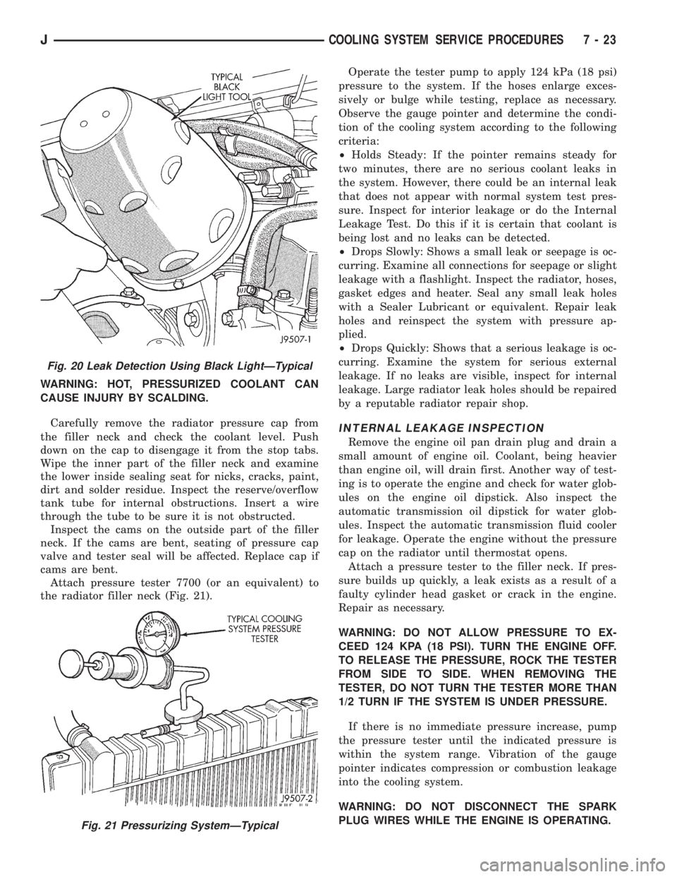
Attach pressure tester 7700 (or an equivalent) to
the radiator filler neck (Fig. 21).Operate the tester pump to apply 124 kPa (18 psi)
pressure to the system. If the hoses enlarge exces-
sively or bulge while testing, replace as necessary.
Observe the gauge pointer and determine the condi-
tion of the cooling system according to the following
criteria:
²Holds Steady: If the pointer remains steady for
two minutes, there are no serious coolant leaks in
the system. However, there could be an internal leak
that does not appear with normal system test pres-
sure. Inspect for interior leakage or do the Internal
Leakage Test. Do this if it is certain that coolant is
being lost and no leaks can be detected.
²Drops Slowly: Shows a small leak or seepage is oc-
curring. Examine all connections for seepage or slight
leakage with a flashlight. Inspect the radiator, hoses,
gasket edges and heater. Seal any small leak holes
with a Sealer Lubricant or equivalent. Repair leak
holes and reinspect the system with pressure ap-
plied.
²Drops Quickly: Shows that a serious leakage is oc-
curring. Examine the system for serious external
leakage. If no leaks are visible, inspect for internal
leakage. Large radiator leak holes should be repaired
by a reputable radiator repair shop.
INTERNAL LEAKAGE INSPECTION
Remove the engine oil pan drain plug and drain a
small amount of engine oil. Coolant, being heavier
than engine oil, will drain first. Another way of test-
ing is to operate the engine and check for water glob-
ules on the engine oil dipstick. Also inspect the
automatic transmission oil dipstick for water glob-
ules. Inspect the automatic transmission fluid cooler
for leakage. Operate the engine without the pressure
cap on the radiator until thermostat opens.
Attach a pressure tester to the filler neck. If pres-
sure builds up quickly, a leak exists as a result of a
faulty cylinder head gasket or crack in the engine.
Repair as necessary.
WARNING: DO NOT ALLOW PRESSURE TO EX-
CEED 124 KPA (18 PSI). TURN THE ENGINE OFF.
TO RELEASE THE PRESSURE, ROCK THE TESTER
FROM SIDE TO SIDE. WHEN REMOVING THE
TESTER, DO NOT TURN THE TESTER MORE THAN
1/2 TURN IF THE SYSTEM IS UNDER PRESSURE.
If there is no immediate pressure increase, pump
the pressure tester until the indicated pressure is
within the system range. Vibration of the gauge
pointer indicates compression or combustion leakage
into the cooling system.
WARNING: DO NOT DISCONNECT THE SPARK
PLUG WIRES WHILE THE ENGINE IS OPERATING.
Fig. 20 Leak Detection Using Black LightÐTypical
Fig. 21 Pressurizing SystemÐTypical
JCOOLING SYSTEM SERVICE PROCEDURES 7 - 23
Page 267 of 2198
(9) After power steering pump has been tightened
into position, recheck belt tension. Adjust if neces-
sary.
BELT SERVICEÐXJ MODELS WITH RIGHT HAND
DRIVE
The automatic belt tensioner is used only on
XJ models equipped with a 4.0L 6-cylinder en-
gine with right hand drive steering system.
REMOVAL
(1) Attach a socket/wrench to the mounting bolt of
the automatic tensioner pulley (Fig. 7).
(2) Rotate the tensioner assembly clockwise (as
viewed from front) until tension has been relieved
from belt.
(3) Remove belt from idler pulley (Fig. 7) first. Re-
move belt from vehicle.
(4) Check condition and alignment of all pulleys.
INSTALLATION
(1) Position the drive belt over all pulleysexcept
the idler pulley (Fig. 7).
CAUTION: When installing the serpentine accessory
drive belt, the belt must be routed correctly. If not,
the engine may overheat due to the water pump ro-
tating in the wrong direction. Refer to (Fig. 6) for
correct engine belt routing. The correct belt with
the correct length must be used
(2) Attach a socket/wrench to the pulley mounting
bolt of the automatic tensioner (Fig. 7).
(3) Rotate the socket/wrench clockwise (Fig. 7).
Place the belt over the idler pulley. Let tensioner ro-
tate back into place. Remove wrench. Be sure belt is
properly seated in the grooves of all pulleys.
AUTOMATIC BELT TENSIONERÐXJ MODELS WITH
RIGHT HAND DRIVE
The automatic belt tensioner is used only on
XJ models equipped with a 4.0L 6-cylinder en-
gine with right hand drive steering system.
The drive belt is equipped with a spring loaded au-
tomatic belt tensioner (Fig. 10). This belt tensioner
will be used with all belt configurations such as with
or without air conditioning.
REMOVAL
(1) Attach a socket/wrench to the mounting bolt of
the automatic tensioner pulley (Fig. 10).
(2) Rotate the tensioner assembly clockwise (as
viewed from front) until tension has been relieved
from belt.
(3) Remove belt from idler pulley (Fig. 10) first.
Remove belt from automatic tensioner.
(4) Remove tensioner mounting bolt (Fig. 10) from
tensioner bracket. Remove tensioner from vehicle.
Note alignment pin on the back of tensioner.
WARNING: BECAUSE OF HIGH SPRING PRES-
SURE, DO NOT ATTEMPT TO DISASSEMBLE AUTO-
MATIC TENSIONER. UNIT IS SERVICED AS AN
ASSEMBLY (EXCEPT FOR PULLEY).
(5) Remove tensioner pulley bolt. Remove pulley
from tensioner.
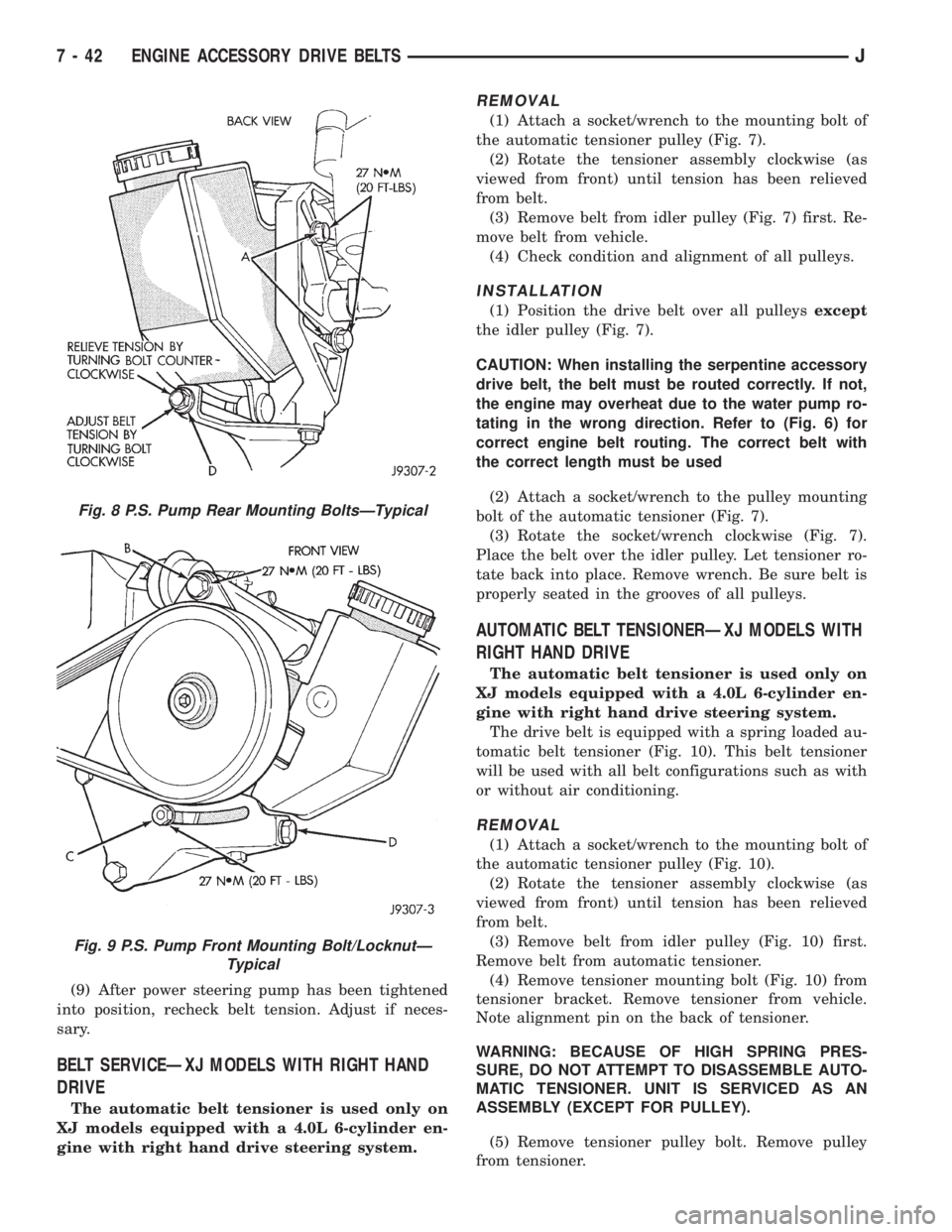
Fig. 8 P.S. Pump Rear Mounting BoltsÐTypical
Fig. 9 P.S. Pump Front Mounting Bolt/LocknutÐ
Typical
7 - 42 ENGINE ACCESSORY DRIVE BELTSJ
Page 268 of 2198
INSTALLATION
(1) Install pulley and pulley bolt to tensioner.
Tighten bolt to 90 Nzm (65 ft. lbs.) torque.
(2) Install tensioner assembly to mounting bracket.
An alignment pin is located on the back of tensioner.
Align this pin to the slotted hole in the mounting
bracket. Install mounting bolt and tighten to 41 Nzm
(30 ft. lbs.) torque. If automatic tensioner bracket-to-
generator mounting bracket bolts were removed,
tighten to 27 Nzm (20 ft. lbs.) torque.
(3) Position the drive belt over all pulleysexcept
the idler pulley (Fig. 10).
CAUTION: When installing the serpentine accessory
drive belt, the belt must be routed correctly. If not,
the engine may overheat due to the water pump ro-
tating in the wrong direction. Refer to (Fig. 6) for
correct engine belt routing. The correct belt with
the correct length must be used
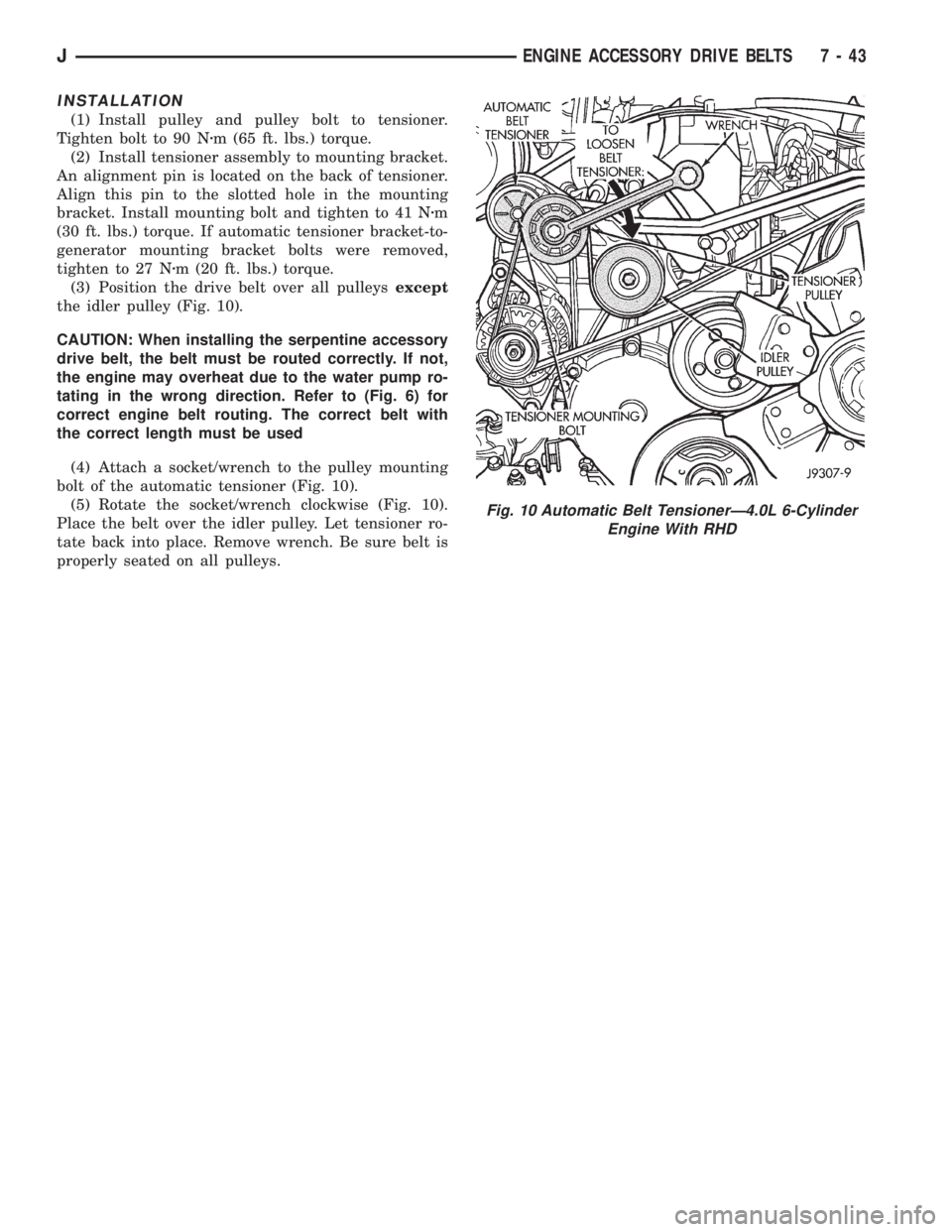
(4) Attach a socket/wrench to the pulley mounting
bolt of the automatic tensioner (Fig. 10).
(5) Rotate the socket/wrench clockwise (Fig. 10).
Place the belt over the idler pulley. Let tensioner ro-
tate back into place. Remove wrench. Be sure belt is
properly seated on all pulleys.
Fig. 10 Automatic Belt TensionerÐ4.0L 6-Cylinder
Engine With RHD
JENGINE ACCESSORY DRIVE BELTS 7 - 43
Page 269 of 2198
ENGINE BLOCK HEATER
GENERAL INFORMATION
DESCRIPTION AND OPERATION
An optional engine block heater is available for all
models. The heater is equipped with a power cord.
The cord is attached to an engine compartment com-
ponent with tie-straps. The heater warms the engine
providing easier engine starting and faster warm-up
in low temperatures. The heater is mounted in a core
hole of the engine cylinder block (in place of a freeze
plug) with the heating element immersed in engine
coolant. Connect the power cord to a grounded 110-
120 volt AC electrical outlet with a grounded, three-
wire extension cord.
WARNING: DO NOT OPERATE ENGINE UNLESS
BLOCK HEATER CORD HAS BEEN DISCONNECTED
FROM POWER SOURCE AND SECURED IN PLACE.
BLOCK HEATER SPECIFICATIONS
²2.5L 4-Cylinder Engine: 115 Volts 400 Watts
²4.0L 6-Cylinder Engine: 120 Volts 600 Watts
REMOVAL
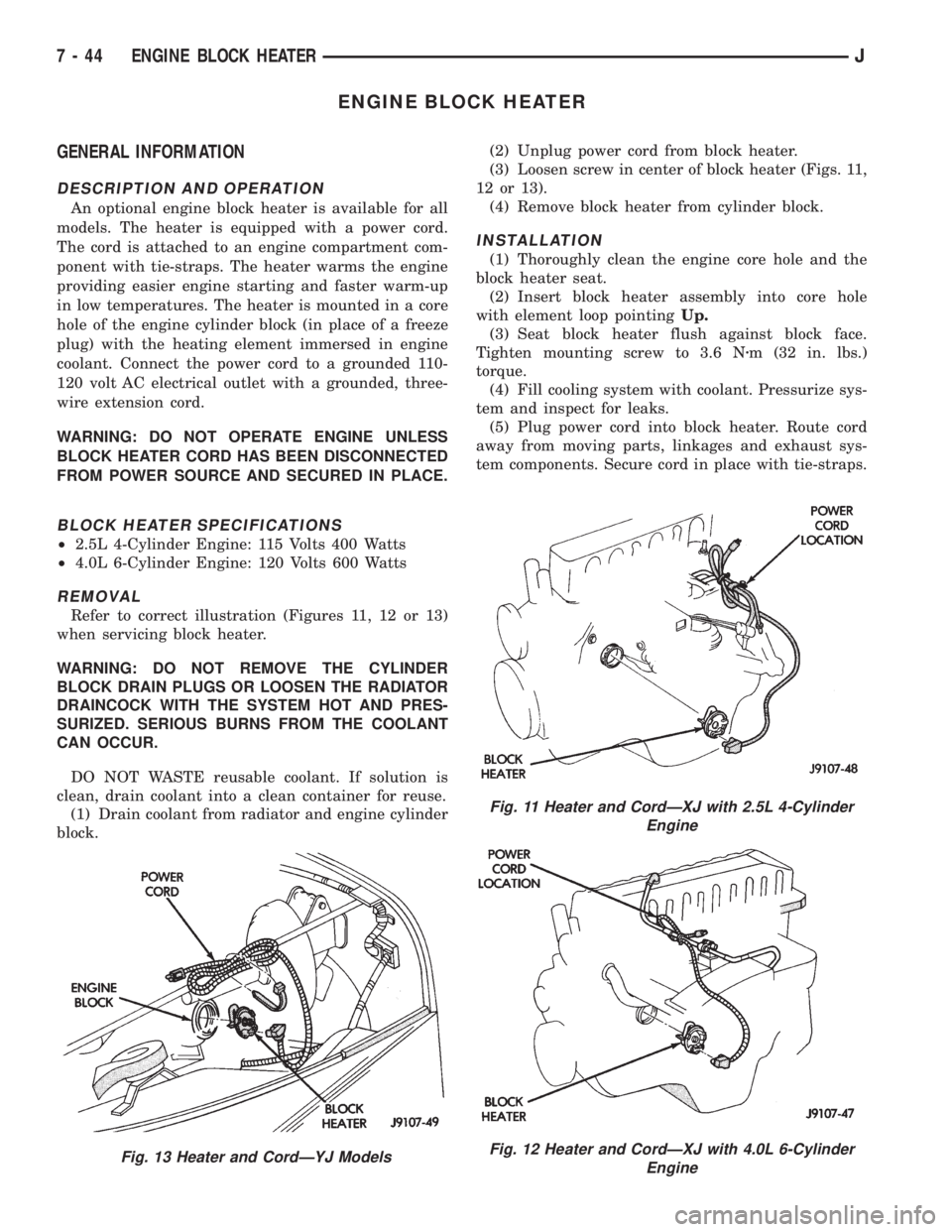
Refer to correct illustration (Figures 11, 12 or 13)
when servicing block heater.
WARNING: DO NOT REMOVE THE CYLINDER
BLOCK DRAIN PLUGS OR LOOSEN THE RADIATOR
DRAINCOCK WITH THE SYSTEM HOT AND PRES-
SURIZED. SERIOUS BURNS FROM THE COOLANT
CAN OCCUR.
DO NOT WASTE reusable coolant. If solution is
clean, drain coolant into a clean container for reuse.
(1) Drain coolant from radiator and engine cylinder
block.(2) Unplug power cord from block heater.
(3) Loosen screw in center of block heater (Figs. 11,
12 or 13).
(4) Remove block heater from cylinder block.
INSTALLATION
(1) Thoroughly clean the engine core hole and the
block heater seat.
(2) Insert block heater assembly into core hole
with element loop pointingUp.
(3) Seat block heater flush against block face.
Tighten mounting screw to 3.6 Nzm (32 in. lbs.)
torque.
(4) Fill cooling system with coolant. Pressurize sys-
tem and inspect for leaks.
(5) Plug power cord into block heater. Route cord
away from moving parts, linkages and exhaust sys-
tem components. Secure cord in place with tie-straps.
Fig. 13 Heater and CordÐYJ Models
Fig. 11 Heater and CordÐXJ with 2.5L 4-Cylinder
Engine
Fig. 12 Heater and CordÐXJ with 4.0L 6-Cylinder
Engine
7 - 44 ENGINE BLOCK HEATERJ
Page 272 of 2198
ELECTRICAL
GROUP INDEX
Group Group
AUDIO SYSTEMS........................ 8F
BATTERY/STARTER/GENERATOR SERVICE.... 8B
BATTERY/STARTING/CHARGING SYSTEMS
DIAGNOSTICS......................... 8A
CHIME/BUZZER WARNING SYSTEMS........ 8U
HORNS................................ 8G
IGNITION SYSTEMS...................... 8D
INSTRUMENT PANEL AND GAUGES......... 8E
LAMPS................................ 8L
OVERHEAD CONSOLE.................... 8C
POWER LOCKS.......................... 8P
POWER MIRRORS....................... 8TPOWER SEATS.......................... 8R
POWER WINDOWS....................... 8S
REAR WINDOW DEFOGGER............... 8N
RESTRAINT SYSTEMS................... 8M
TURN SIGNAL AND HAZARD WARNING
SYSTEMS............................. 8J
VEHICLE SPEED CONTROL SYSTEM......... 8H
WIPER AND WASHER SYSTEMS............ 8K
XJ WIRING DIAGRAMS-LEFT HAND DRIVE . . . 8W
XJ WIRING DIAGRAMS-RIGHT HAND DRIVE . 8W
YJ WIRING DIAGRAMS.................. 8W
BATTERY/STARTING/CHARGING SYSTEMS DIAGNOSTICS
CONTENTS
page page
BATTERY............................... 2
CHARGING SYSTEM..................... 17
IGNITION-OFF DRAW.................... 10SPECIFICATIONS........................ 23
STARTING SYSTEM...................... 11
USING ON-BOARD DIAGNOSTIC SYSTEM.... 22
GENERAL INFORMATION
The battery, starting, and charging systems operate
with one another; therefore, they must be tested as a
complete system. In order for the vehicle to start and
charge properly, all of the components involved in
these systems must perform within specifications.
Group 8A covers battery, starting (Fig. 1) and
charging (Fig. 2) system diagnostic procedures. These
procedures include the most basic conventional diag-
nostic methods, to On-Board Diagnostics (OBD) builtinto the Powertrain Control Module (PCM). Use of an
induction milliamp ammeter, volt/ohmmeter, battery
charger, carbon pile rheostat (load tester), and 12-
volt test lamp will be required.
All OBD-sensed systems are monitored by the
PCM. Each monitored circuit is assigned a Diagnos-
tic Trouble Code (DTC). The PCM will store a DTC in
electronic memory for any failure it detects. See Us-
ing On-Board Diagnostic System in this group for
more information.
JELECTRICAL 8A - 1
Page 319 of 2198
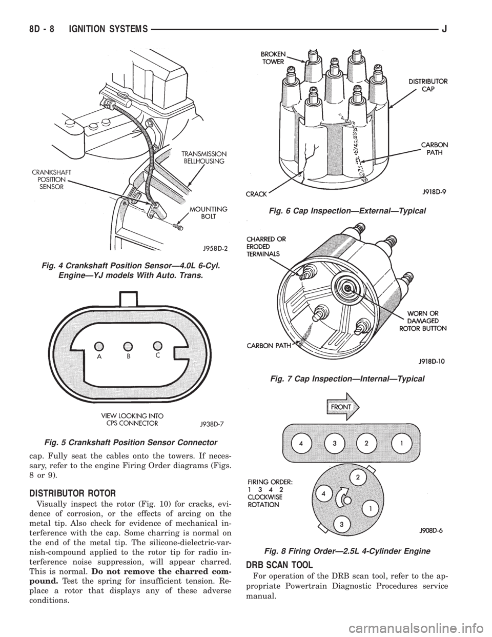
cap. Fully seat the cables onto the towers. If neces-
sary, refer to the engine Firing Order diagrams (Figs.
8or9).
DISTRIBUTOR ROTOR
Visually inspect the rotor (Fig. 10) for cracks, evi-
dence of corrosion, or the effects of arcing on the
metal tip. Also check for evidence of mechanical in-
terference with the cap. Some charring is normal on
the end of the metal tip. The silicone-dielectric-var-
nish-compound applied to the rotor tip for radio in-
terference noise suppression, will appear charred.
This is normal.Do not remove the charred com-
pound.Test the spring for insufficient tension. Re-
place a rotor that displays any of these adverse
conditions.
DRB SCAN TOOL
For operation of the DRB scan tool, refer to the ap-
propriate Powertrain Diagnostic Procedures service
manual.
Fig. 4 Crankshaft Position SensorÐ4.0L 6-Cyl.
EngineÐYJ models With Auto. Trans.
Fig. 5 Crankshaft Position Sensor Connector
Fig. 6 Cap InspectionÐExternalÐTypical
Fig. 7 Cap InspectionÐInternalÐTypical
Fig. 8 Firing OrderÐ2.5L 4-Cylinder Engine
8D - 8 IGNITION SYSTEMSJ
Page 325 of 2198
temperature ranges. This depends upon the thick-
ness and length of the center electrodes porcelain in-
sulator.)
SPARK PLUG OVERHEATING
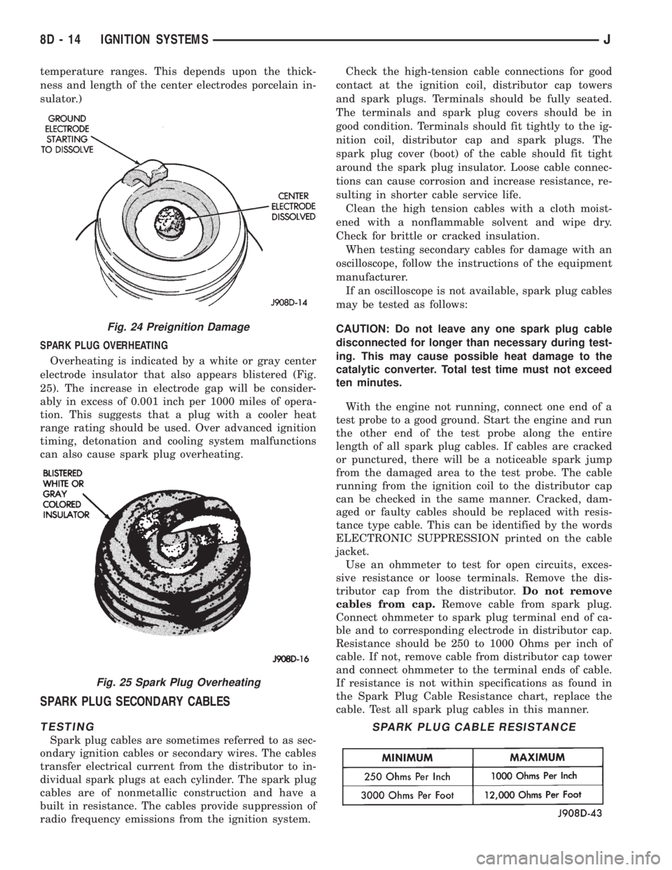
Overheating is indicated by a white or gray center
electrode insulator that also appears blistered (Fig.
25). The increase in electrode gap will be consider-
ably in excess of 0.001 inch per 1000 miles of opera-
tion. This suggests that a plug with a cooler heat
range rating should be used. Over advanced ignition
timing, detonation and cooling system malfunctions
can also cause spark plug overheating.
SPARK PLUG SECONDARY CABLES
TESTING
Spark plug cables are sometimes referred to as sec-
ondary ignition cables or secondary wires. The cables
transfer electrical current from the distributor to in-
dividual spark plugs at each cylinder. The spark plug
cables are of nonmetallic construction and have a
built in resistance. The cables provide suppression of
radio frequency emissions from the ignition system.Check the high-tension cable connections for good
contact at the ignition coil, distributor cap towers
and spark plugs. Terminals should be fully seated.
The terminals and spark plug covers should be in
good condition. Terminals should fit tightly to the ig-
nition coil, distributor cap and spark plugs. The
spark plug cover (boot) of the cable should fit tight
around the spark plug insulator. Loose cable connec-
tions can cause corrosion and increase resistance, re-
sulting in shorter cable service life.
Clean the high tension cables with a cloth moist-
ened with a nonflammable solvent and wipe dry.
Check for brittle or cracked insulation.
When testing secondary cables for damage with an
oscilloscope, follow the instructions of the equipment
manufacturer.
If an oscilloscope is not available, spark plug cables
may be tested as follows:
CAUTION: Do not leave any one spark plug cable
disconnected for longer than necessary during test-
ing. This may cause possible heat damage to the
catalytic converter. Total test time must not exceed
ten minutes.
With the engine not running, connect one end of a
test probe to a good ground. Start the engine and run
the other end of the test probe along the entire
length of all spark plug cables. If cables are cracked
or punctured, there will be a noticeable spark jump
from the damaged area to the test probe. The cable
running from the ignition coil to the distributor cap
can be checked in the same manner. Cracked, dam-
aged or faulty cables should be replaced with resis-
tance type cable. This can be identified by the words
ELECTRONIC SUPPRESSION printed on the cable
jacket.
Use an ohmmeter to test for open circuits, exces-
sive resistance or loose terminals. Remove the dis-
tributor cap from the distributor.Do not remove
cables from cap.Remove cable from spark plug.
Connect ohmmeter to spark plug terminal end of ca-
ble and to corresponding electrode in distributor cap.
Resistance should be 250 to 1000 Ohms per inch of
cable. If not, remove cable from distributor cap tower
and connect ohmmeter to the terminal ends of cable.
If resistance is not within specifications as found in
the Spark Plug Cable Resistance chart, replace the
cable. Test all spark plug cables in this manner.
Fig. 24 Preignition Damage
Fig. 25 Spark Plug Overheating
SPARK PLUG CABLE RESISTANCE
8D - 14 IGNITION SYSTEMSJ
Page 330 of 2198
CAUTION: On some models, two bolts are used to
secure the sensor to the transmission. These bolts
are specially machined to correctly space the unit
to the flywheel. Do not attempt to install any other
bolts.
(3) Connect the electrical connector to the sensor.
(4) Install clip on sensor wire harness.
(5) Install clip over fuel rail mounting stud. Install
clip mounting nut.
INSTALLATIONÐYJ MODELS WITH 4.0L
6-CYLINDER ENGINE AND AUTOMATIC
TRANSMISSION
(1) Install the sensor into the access hole on the
transmission.
(2) Install sensor mounting bolt (Fig. 6).
(3) Tighten sensor mounting bolt to 6-to-8 Nzm (50-
to-70 in. lbs.) torque.
(4) Connect the electrical connector to sensor.
(5) Install the clip to sensor wire harness.
(6) Install clip over fuel rail mounting stud. Install
clip mounting nut.
ENGINE COOLANT TEMPERATURE SENSOR
For an operational description, diagnosis and re-
moval/installation procedures, refer to Group 14,
Fuel System.
DISTRIBUTOR
GENERAL INFORMATION
All distributors contain an internal oil seal that
prevents oil from entering the distributor housing.
The seal is not serviceable.
Factory replacement distributors are equipped with
a plastic alignment pin already installed. The pin is
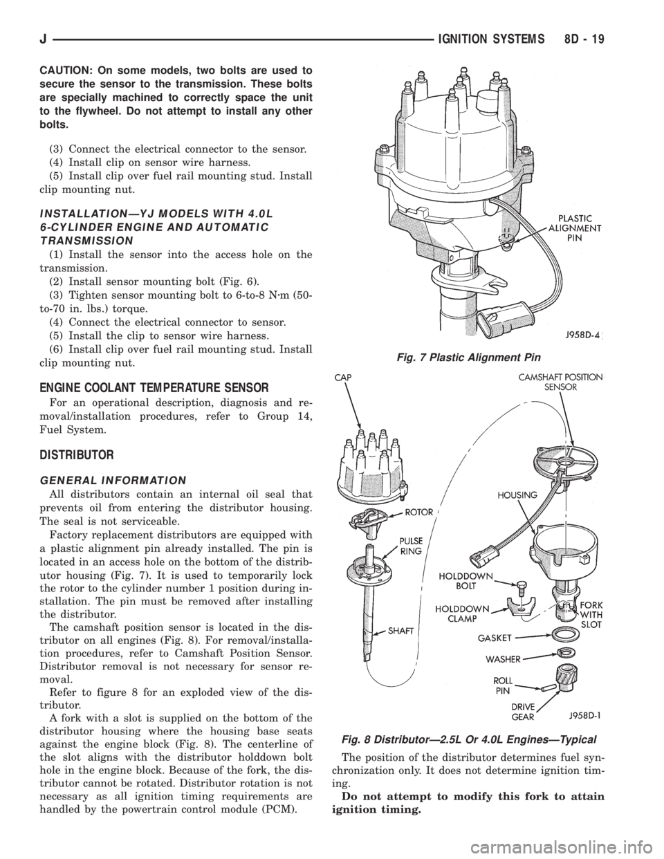
located in an access hole on the bottom of the distrib-
utor housing (Fig. 7). It is used to temporarily lock
the rotor to the cylinder number 1 position during in-
stallation. The pin must be removed after installing
the distributor.
The camshaft position sensor is located in the dis-
tributor on all engines (Fig. 8). For removal/installa-
tion procedures, refer to Camshaft Position Sensor.
Distributor removal is not necessary for sensor re-
moval.
Refer to figure 8 for an exploded view of the dis-
tributor.
A fork with a slot is supplied on the bottom of the
distributor housing where the housing base seats
against the engine block (Fig. 8). The centerline of
the slot aligns with the distributor holddown bolt
hole in the engine block. Because of the fork, the dis-
tributor cannot be rotated. Distributor rotation is not
necessary as all ignition timing requirements are
handled by the powertrain control module (PCM).The position of the distributor determines fuel syn-
chronization only. It does not determine ignition tim-
ing.
Do not attempt to modify this fork to attain
ignition timing.
Fig. 7 Plastic Alignment Pin
Fig. 8 DistributorÐ2.5L Or 4.0L EnginesÐTypical
JIGNITION SYSTEMS 8D - 19