1995 JEEP CHEROKEE thermostat
[x] Cancel search: thermostatPage 226 of 2198
COOLING SYSTEM
CONTENTS
page page
DIAGNOSIS............................. 4
ENGINE ACCESSORY DRIVE BELTS......... 38
ENGINE BLOCK HEATER.................. 44GENERAL INFORMATION.................. 1
SERVICE PROCEDURES.................. 13
SPECIFICATIONS........................ 45
GENERAL INFORMATION
Throughout this group, references are made to par-
ticular vehicle models by alphabetical designation
(XJ or YJ) or by the particular vehicle nameplate. A
chart showing a breakdown of alphabetical designa-
tions is included in the Introduction section at the
beginning of this manual.
COOLING SYSTEM
The cooling system regulates engine operating tem-
perature. It allows the engine to reach normal oper-
ating temperature as quickly as possible, maintains
normal operating temperature and prevents over-
heating.
The cooling system also provides a means of heat-
ing the passenger compartment and cooling the auto-
matic transmission fluid (if equipped). The cooling
system is pressurized and uses a centrifugal water
pump to circulate coolant throughout the system.
An optional factory installed heavy duty cooling
package is available on most models. The package
consists of a radiator that has an increased number
of cooling fins. XJ models equipped with a 4.0L 6-cyl-inder engine and heavy duty cooling and/or air con-
ditioning also have an auxiliary electric cooling fan.
COOLING SYSTEM COMPONENTS
The cooling system consists of:
²A radiator
²Cooling fan (mechanical and/or electrical)
²Thermal viscous fan drive
²Fan shroud
²Radiator pressure cap
²Thermostat
²Coolant reserve/overflow system
²Transmission oil cooler (if equipped with an auto-
matic transmission)
²Coolant
²Water pump
²Hoses and hose clamps
SYSTEM COOLANT ROUTING
For cooling system flow routings, refer to Figs. 1, 2,
3or4.
JCOOLING SYSTEM 7 - 1
Page 229 of 2198
DIAGNOSIS
INDEX
page page
DRB Scan Tool............................ 5
On-Board Diagnostics (OBD).................. 4Preliminary Checks......................... 5
ON-BOARD DIAGNOSTICS (OBD)
FOR CERTAIN COOLING SYSTEM
COMPONENTS
The powertrain control module (PCM) has been
programmed to monitor the certain following cooling
system components:
²If the engine has remained cool for too long a pe-
riod, such as with a stuck open thermostat, a Diag-
nostic Trouble Code (DTC) number 17 can be
observed at the malfunction indicator lamp. This
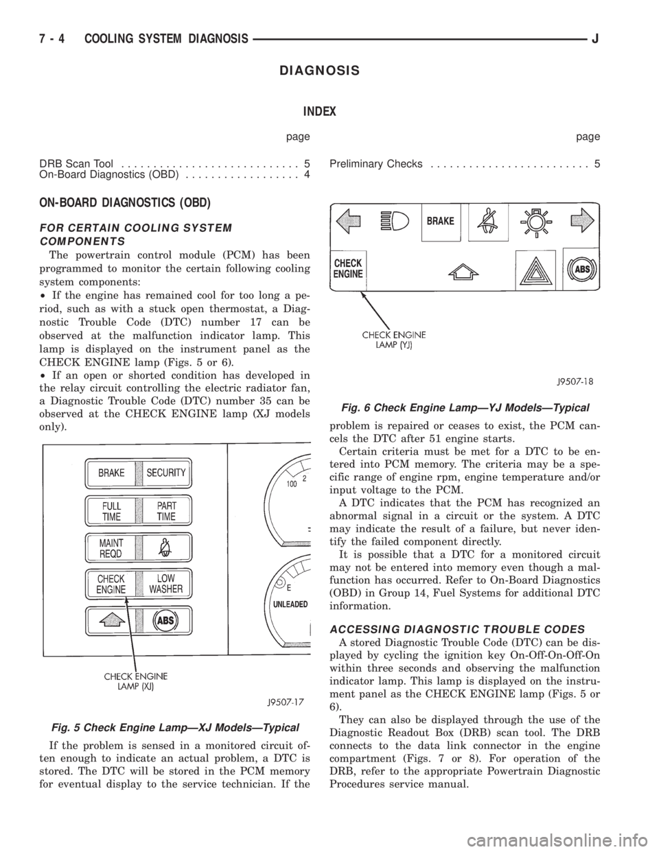
lamp is displayed on the instrument panel as the
CHECK ENGINE lamp (Figs. 5 or 6).
²If an open or shorted condition has developed in
the relay circuit controlling the electric radiator fan,
a Diagnostic Trouble Code (DTC) number 35 can be
observed at the CHECK ENGINE lamp (XJ models
only).
If the problem is sensed in a monitored circuit of-
ten enough to indicate an actual problem, a DTC is
stored. The DTC will be stored in the PCM memory
for eventual display to the service technician. If theproblem is repaired or ceases to exist, the PCM can-
cels the DTC after 51 engine starts.
Certain criteria must be met for a DTC to be en-
tered into PCM memory. The criteria may be a spe-
cific range of engine rpm, engine temperature and/or
input voltage to the PCM.
A DTC indicates that the PCM has recognized an
abnormal signal in a circuit or the system. A DTC
may indicate the result of a failure, but never iden-
tify the failed component directly.
It is possible that a DTC for a monitored circuit
may not be entered into memory even though a mal-
function has occurred. Refer to On-Board Diagnostics
(OBD) in Group 14, Fuel Systems for additional DTC
information.
ACCESSING DIAGNOSTIC TROUBLE CODES
A stored Diagnostic Trouble Code (DTC) can be dis-
played by cycling the ignition key On-Off-On-Off-On
within three seconds and observing the malfunction
indicator lamp. This lamp is displayed on the instru-
ment panel as the CHECK ENGINE lamp (Figs. 5 or
6).
They can also be displayed through the use of the
Diagnostic Readout Box (DRB) scan tool. The DRB
connects to the data link connector in the engine
compartment (Figs. 7 or 8). For operation of the
DRB, refer to the appropriate Powertrain Diagnostic
Procedures service manual.
Fig. 5 Check Engine LampÐXJ ModelsÐTypical
Fig. 6 Check Engine LampÐYJ ModelsÐTypical
7 - 4 COOLING SYSTEM DIAGNOSISJ
Page 238 of 2198
SERVICE PROCEDURES
INDEX
page page
Auxiliary Electric Cooling FanÐXJ Models with 4.0L
6-Cylinder Engine....................... 35
Coolant................................. 20
Coolant Reserve/Overflow System............. 24
Cooling System Cleaning/Reverse Flushing...... 22
Cooling System Fans...................... 32
Cooling System Hoses..................... 32
Draining Cooling System.................... 21
Radiator Pressure Cap..................... 25
Radiators............................... 26Refilling Cooling System.................... 21
Testing Cooling System for Leaks............. 22
Thermostat.............................. 17
Transmission Oil Coolers.................... 36
Viscous Fan Drive......................... 34
Water Pump Tests......................... 13
Water PumpsÐGeneral Information............ 13
Water PumpsÐRemoval/Installation........... 14
WATER PUMPSÐGENERAL INFORMATION
A centrifugal water pump circulates coolant
through the water jackets, passages, intake manifold,
radiator core, cooling system hoses and heater core.
The pump is driven from the engine crankshaft by a
drive belt on all engines.
The water pump impeller is pressed onto the rear
of a shaft that rotates in bearings pressed into the
housing. The housing has a small hole to allow seep-
age to escape. The water pump seals are lubricated
by the antifreeze in the coolant mixture. No addi-
tional lubrication is necessary.
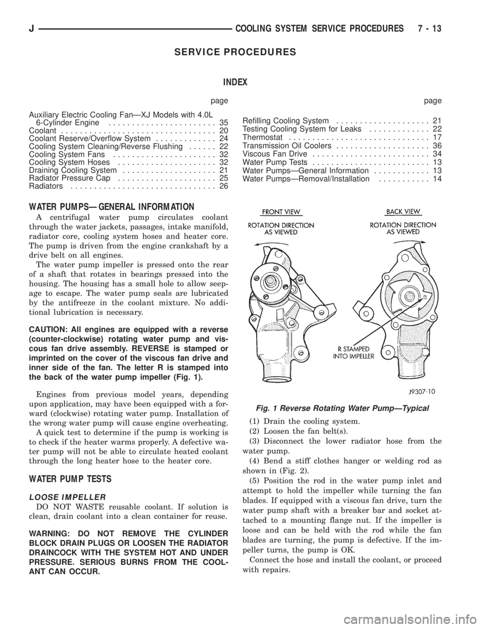
CAUTION: All engines are equipped with a reverse
(counter-clockwise) rotating water pump and vis-
cous fan drive assembly. REVERSE is stamped or
imprinted on the cover of the viscous fan drive and
inner side of the fan. The letter R is stamped into
the back of the water pump impeller (Fig. 1).
Engines from previous model years, depending
upon application, may have been equipped with a for-
ward (clockwise) rotating water pump. Installation of
the wrong water pump will cause engine overheating.
A quick test to determine if the pump is working is
to check if the heater warms properly. A defective wa-
ter pump will not be able to circulate heated coolant
through the long heater hose to the heater core.
WATER PUMP TESTS
LOOSE IMPELLER
DO NOT WASTE reusable coolant. If solution is
clean, drain coolant into a clean container for reuse.
WARNING: DO NOT REMOVE THE CYLINDER
BLOCK DRAIN PLUGS OR LOOSEN THE RADIATOR
DRAINCOCK WITH THE SYSTEM HOT AND UNDER
PRESSURE. SERIOUS BURNS FROM THE COOL-
ANT CAN OCCUR.(1) Drain the cooling system.
(2) Loosen the fan belt(s).
(3) Disconnect the lower radiator hose from the
water pump.
(4) Bend a stiff clothes hanger or welding rod as
shown in (Fig. 2).
(5) Position the rod in the water pump inlet and
attempt to hold the impeller while turning the fan
blades. If equipped with a viscous fan drive, turn the
water pump shaft with a breaker bar and socket at-
tached to a mounting flange nut. If the impeller is
loose and can be held with the rod while the fan
blades are turning, the pump is defective. If the im-
peller turns, the pump is OK.
Connect the hose and install the coolant, or proceed
with repairs.
Fig. 1 Reverse Rotating Water PumpÐTypical
JCOOLING SYSTEM SERVICE PROCEDURES 7 - 13
Page 242 of 2198
INSTALLATIONÐALL MODELS
(1) If pump is being replaced, install the heater
hose fitting to the pump. Use a sealant on the fitting
such as MoparŸ Thread Sealant With Teflon. Refer
to the directions on the package.
(2) Clean the gasket mating surfaces. If the origi-
nal pump is used, remove any deposits or other for-
eign material. Inspect the cylinder block and water
pump mating surfaces for erosion or damage from
cavitation.
(3) Install the gasket and water pump. The silicone
bead on the gasket should be facing the water pump.
Also, the gasket is installed dry. Tighten mounting
bolts to 30 Nzm (22 ft. lbs.) torque. Rotate the shaft
by hand to be sure it turns freely.
(4) Connect the radiator and heater hoses to the
water pump.
(5) Position water pump pulley to water pump hub.
(6) If equipped with a water pump mounted fan,
install fan and four nuts to water pump hub. If not
equipped with a water pump mounted fan, install
four pump hub bolts. Tighten bolts (or nuts) to 27
Nzm (20 ft. lbs.) torque.
(7) Position power steering pump bracket to en-
gine. Install bolts E, F and G (Fig. 7). Tighten bolts F
andGto38Nzm (28 ft. lbs.) torque. Tighten bolt E to
27 Nzm (20 ft. lbs.) torque.
(8) Position power steering pump to mounting
bracket. Install pivot bolt B (Fig. 6) finger tight. In-
stall locknut C and adjustment bolt D (Figs. 6 or 7)
finger tight.
(9) Install two adjustment bolts A (Fig. 6) finger
tight.
(10) Install idler pulley.
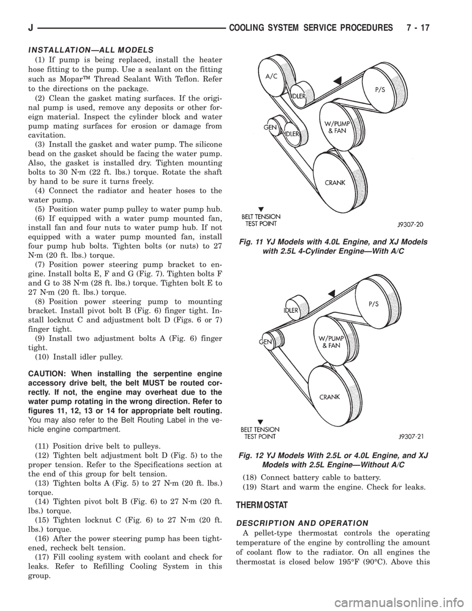
CAUTION: When installing the serpentine engine
accessory drive belt, the belt MUST be routed cor-
rectly. If not, the engine may overheat due to the
water pump rotating in the wrong direction. Refer to
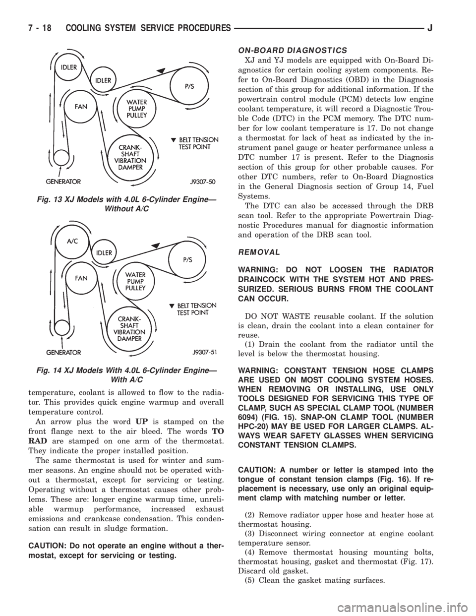
figures 11, 12, 13 or 14 for appropriate belt routing.
You may also refer to the Belt Routing Label in the ve-
hicle engine compartment.
(11) Position drive belt to pulleys.
(12) Tighten belt adjustment bolt D (Fig. 5) to the
proper tension. Refer to the Specifications section at
the end of this group for belt tension.
(13) Tighten bolts A (Fig. 5) to 27 Nzm (20 ft. lbs.)
torque.
(14) Tighten pivot bolt B (Fig. 6) to 27 Nzm (20 ft.
lbs.) torque.
(15) Tighten locknut C (Fig. 6) to 27 Nzm (20 ft.
lbs.) torque.
(16) After the power steering pump has been tight-
ened, recheck belt tension.
(17) Fill cooling system with coolant and check for
leaks. Refer to Refilling Cooling System in this
group.(18) Connect battery cable to battery.
(19) Start and warm the engine. Check for leaks.
THERMOSTAT
DESCRIPTION AND OPERATION
A pellet-type thermostat controls the operating
temperature of the engine by controlling the amount
of coolant flow to the radiator. On all engines the
thermostat is closed below 195ÉF (90ÉC). Above this
Fig. 11 YJ Models with 4.0L Engine, and XJ Models
with 2.5L 4-Cylinder EngineÐWith A/C
Fig. 12 YJ Models With 2.5L or 4.0L Engine, and XJ
Models with 2.5L EngineÐWithout A/C
JCOOLING SYSTEM SERVICE PROCEDURES 7 - 17
Page 243 of 2198
temperature, coolant is allowed to flow to the radia-
tor. This provides quick engine warmup and overall
temperature control.
An arrow plus the wordUPis stamped on the
front flange next to the air bleed. The wordsTO
RADare stamped on one arm of the thermostat.
They indicate the proper installed position.
The same thermostat is used for winter and sum-
mer seasons. An engine should not be operated with-
out a thermostat, except for servicing or testing.
Operating without a thermostat causes other prob-
lems. These are: longer engine warmup time, unreli-
able warmup performance, increased exhaust
emissions and crankcase condensation. This conden-
sation can result in sludge formation.
CAUTION: Do not operate an engine without a ther-
mostat, except for servicing or testing.
ON-BOARD DIAGNOSTICS
XJ and YJ models are equipped with On-Board Di-
agnostics for certain cooling system components. Re-
fer to On-Board Diagnostics (OBD) in the Diagnosis
section of this group for additional information. If the
powertrain control module (PCM) detects low engine
coolant temperature, it will record a Diagnostic Trou-
ble Code (DTC) in the PCM memory. The DTC num-
ber for low coolant temperature is 17. Do not change
a thermostat for lack of heat as indicated by the in-
strument panel gauge or heater performance unless a
DTC number 17 is present. Refer to the Diagnosis
section of this group for other probable causes. For
other DTC numbers, refer to On-Board Diagnostics
in the General Diagnosis section of Group 14, Fuel
Systems.
The DTC can also be accessed through the DRB
scan tool. Refer to the appropriate Powertrain Diag-
nostic Procedures manual for diagnostic information
and operation of the DRB scan tool.
REMOVAL
WARNING: DO NOT LOOSEN THE RADIATOR
DRAINCOCK WITH THE SYSTEM HOT AND PRES-
SURIZED. SERIOUS BURNS FROM THE COOLANT
CAN OCCUR.
DO NOT WASTE reusable coolant. If the solution
is clean, drain the coolant into a clean container for
reuse.
(1) Drain the coolant from the radiator until the
level is below the thermostat housing.
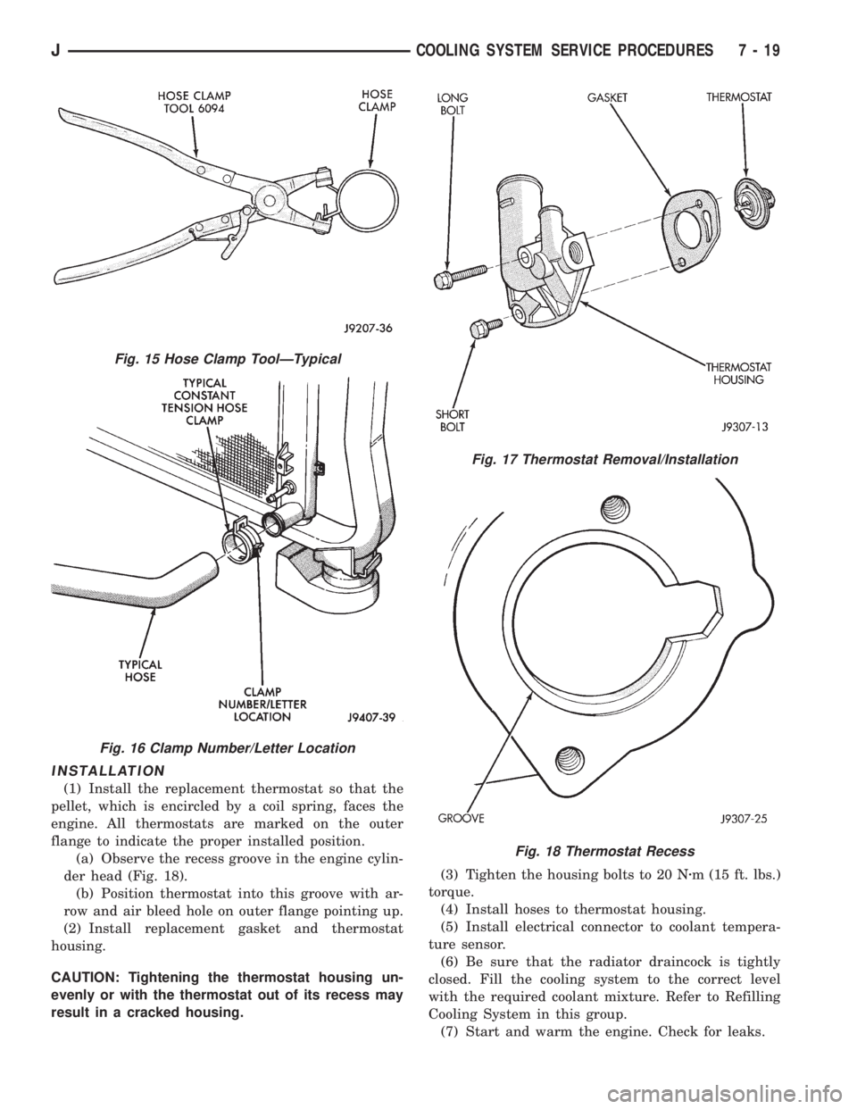
WARNING: CONSTANT TENSION HOSE CLAMPS
ARE USED ON MOST COOLING SYSTEM HOSES.
WHEN REMOVING OR INSTALLING, USE ONLY
TOOLS DESIGNED FOR SERVICING THIS TYPE OF
CLAMP, SUCH AS SPECIAL CLAMP TOOL (NUMBER
6094) (FIG. 15). SNAP-ON CLAMP TOOL (NUMBER
HPC-20) MAY BE USED FOR LARGER CLAMPS. AL-
WAYS WEAR SAFETY GLASSES WHEN SERVICING
CONSTANT TENSION CLAMPS.
CAUTION: A number or letter is stamped into the
tongue of constant tension clamps (Fig. 16). If re-
placement is necessary, use only an original equip-
ment clamp with matching number or letter.
(2) Remove radiator upper hose and heater hose at
thermostat housing.
(3) Disconnect wiring connector at engine coolant
temperature sensor.
(4) Remove thermostat housing mounting bolts,
thermostat housing, gasket and thermostat (Fig. 17).
Discard old gasket.
(5) Clean the gasket mating surfaces.
Fig. 13 XJ Models with 4.0L 6-Cylinder EngineÐ
Without A/C
Fig. 14 XJ Models With 4.0L 6-Cylinder EngineÐ
With A/C
7 - 18 COOLING SYSTEM SERVICE PROCEDURESJ
Page 244 of 2198
INSTALLATION
(1) Install the replacement thermostat so that the
pellet, which is encircled by a coil spring, faces the
engine. All thermostats are marked on the outer
flange to indicate the proper installed position.
(a) Observe the recess groove in the engine cylin-
der head (Fig. 18).
(b) Position thermostat into this groove with ar-
row and air bleed hole on outer flange pointing up.
(2) Install replacement gasket and thermostat
housing.
CAUTION: Tightening the thermostat housing un-
evenly or with the thermostat out of its recess may
result in a cracked housing.(3) Tighten the housing bolts to 20 Nzm (15 ft. lbs.)
torque.
(4) Install hoses to thermostat housing.
(5) Install electrical connector to coolant tempera-
ture sensor.
(6) Be sure that the radiator draincock is tightly
closed. Fill the cooling system to the correct level
with the required coolant mixture. Refer to Refilling
Cooling System in this group.
(7) Start and warm the engine. Check for leaks.
Fig. 15 Hose Clamp ToolÐTypical
Fig. 16 Clamp Number/Letter Location
Fig. 17 Thermostat Removal/Installation
Fig. 18 Thermostat Recess
JCOOLING SYSTEM SERVICE PROCEDURES 7 - 19
Page 246 of 2198
Low coolant level can cause thermostat pellet to be
suspended in air instead of coolant. This will cause
thermostat to open later, which in turn causes higher
coolant temperature. Air trapped in cooling system
also reduces amount of coolant circulating in heater
core resulting in low heat output.
DEAERATION
As the engine operates, any air trapped in cooling
system gathers under the radiator cap. The next time
the engine is operated, thermal expansion of coolant
will push any trapped air past radiator cap into the
coolant reserve/overflow tank. Here it escapes to the
atmosphere into the tank. When the engine cools
down the coolant, it will be drawn from the reserve/
overflow tank into the radiator to replace any re-
moved air.
DRAINING COOLING SYSTEM
ALL MODELSÐEXCEPT XJ WITH 4.0L
6-CYLINDER ENGINE
WARNING: DO NOT REMOVE THE CYLINDER
BLOCK DRAIN PLUGS OR LOOSEN THE RADIATOR
DRAINCOCK WITH SYSTEM HOT AND UNDER
PRESSURE. SERIOUS BURNS FROM COOLANT
CAN OCCUR.
DO NOT WASTE reusable coolant. If the solution
is clean, drain the coolant into a clean container for
reuse.
DO NOT remove the radiator cap when draining
the coolant from the reserve/overflow tank. Open the
radiator draincock and when the tank is empty, re-
move the radiator cap. The coolant does not have to
be removed from the tank unless the system is being
refilled with a fresh mixture.
(1) Drain the coolant from the radiator by loosen-
ing the draincock.
(2) Drain coolant from engine as follows:
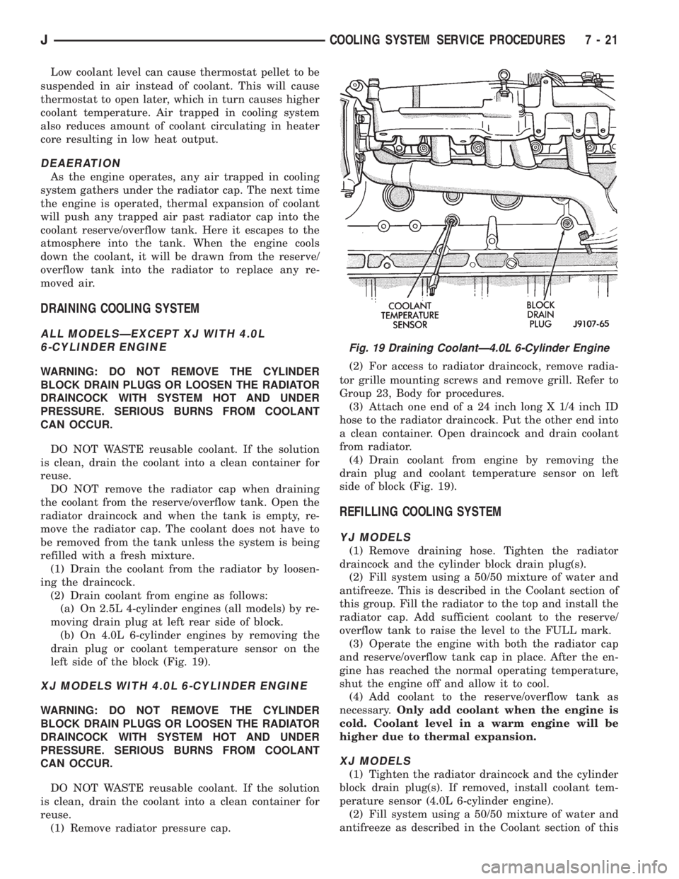
(a) On 2.5L 4-cylinder engines (all models) by re-
moving drain plug at left rear side of block.
(b) On 4.0L 6-cylinder engines by removing the
drain plug or coolant temperature sensor on the
left side of the block (Fig. 19).
XJ MODELS WITH 4.0L 6-CYLINDER ENGINE
WARNING: DO NOT REMOVE THE CYLINDER
BLOCK DRAIN PLUGS OR LOOSEN THE RADIATOR
DRAINCOCK WITH SYSTEM HOT AND UNDER
PRESSURE. SERIOUS BURNS FROM COOLANT
CAN OCCUR.
DO NOT WASTE reusable coolant. If the solution
is clean, drain the coolant into a clean container for
reuse.
(1) Remove radiator pressure cap.(2) For access to radiator draincock, remove radia-
tor grille mounting screws and remove grill. Refer to
Group 23, Body for procedures.
(3) Attach one end of a 24 inch long X 1/4 inch ID
hose to the radiator draincock. Put the other end into
a clean container. Open draincock and drain coolant
from radiator.
(4) Drain coolant from engine by removing the
drain plug and coolant temperature sensor on left
side of block (Fig. 19).
REFILLING COOLING SYSTEM
YJ MODELS
(1) Remove draining hose. Tighten the radiator
draincock and the cylinder block drain plug(s).
(2) Fill system using a 50/50 mixture of water and
antifreeze. This is described in the Coolant section of
this group. Fill the radiator to the top and install the
radiator cap. Add sufficient coolant to the reserve/
overflow tank to raise the level to the FULL mark.
(3) Operate the engine with both the radiator cap
and reserve/overflow tank cap in place. After the en-
gine has reached the normal operating temperature,
shut the engine off and allow it to cool.
(4) Add coolant to the reserve/overflow tank as
necessary.Only add coolant when the engine is
cold. Coolant level in a warm engine will be
higher due to thermal expansion.
XJ MODELS
(1) Tighten the radiator draincock and the cylinder
block drain plug(s). If removed, install coolant tem-
perature sensor (4.0L 6-cylinder engine).
(2) Fill system using a 50/50 mixture of water and
antifreeze as described in the Coolant section of this
Fig. 19 Draining CoolantÐ4.0L 6-Cylinder Engine
JCOOLING SYSTEM SERVICE PROCEDURES 7 - 21
Page 247 of 2198
group. Fill radiator to top and install radiator cap.
Add sufficient coolant to reserve/overflow tank to
raise level to FULL mark.
(3) With heater control unit in the HEAT position,
operate engine with radiator cap in place.
(4) After engine has reached normal operating
temperature, shut engine off and allow it to cool.
(5) Add coolant to reserve/overflow tank as neces-
sary.Only add coolant when the engine is cold.
Coolant level in a warm engine will be higher
due to thermal expansion.
COOLING SYSTEM CLEANING/REVERSE FLUSHING
CAUTION: The cooling system normally operates at
97-to-124 kPa (14-to-18 psi) pressure. Exceeding
this pressure may damage the radiator or hoses.
CLEANING
Drain cooling system and refill with water. Run en-
gine with radiator cap installed until upper radiator
hose is hot. Stop engine and drain water from sys-
tem. If water is dirty, fill system with water, run en-
gine and drain system. Repeat until water drains
clean.
REVERSE FLUSHING
Reverse flushing of the cooling system is the forc-
ing of water through the cooling system. This is done
using air pressure in the opposite direction of normal
coolant flow. It is usually only necessary with very
dirty systems with evidence of partial plugging.
REVERSE FLUSHING RADIATOR
Disconnect the radiator hoses from the radiator fit-
tings. Attach a section of radiator hose to the radia-
tor bottom outlet fitting and insert the flushing gun.
Connect a water supply hose and air supply hose to
the flushing gun.
CAUTION: The cooling system normally operates at
97-to-124 kPa (14-to-18 psi) pressure. Exceeding
this pressure may damage the radiator or hoses.
Allow the radiator to fill with water. When radiator
is filled, apply air in short blasts allowing radiator to
refill between blasts. Continue this reverse flushing
until clean water flows out through rear of radiator
cooling tube passages. For more information, refer to
operating instructions supplied with flushing equip-
ment. Have radiator cleaned more extensively by a
radiator repair shop.
REVERSE FLUSHING ENGINE
Drain the cooling system. Remove the thermostat
housing and thermostat. Install the thermostat hous-
ing. Disconnect the radiator upper hose from the ra-
diator and attach the flushing gun to the hose.Disconnect the radiator lower hose from the water
pump. Attach a lead away hose to the water pump
inlet fitting.
CAUTION: On XJ models, be sure that the heater
control valve is closed (heat off). This is done to
prevent coolant flow with scale and other deposits
from entering the heater core.
Connect the water supply hose and air supply hose
to the flushing gun. Allow the engine to fill with wa-
ter. When the engine is filled, apply air in short
blasts, allowing the system to fill between air blasts.
Continue until clean water flows through the lead
away hose. For more information, refer to operating
instructions supplied with flushing equipment.
Remove the lead away hose, flushing gun, water
supply hose and air supply hose. Remove the thermo-
stat housing and install thermostat. Install the ther-
mostat housing with a replacement gasket. Refer to
Thermostat Replacement. Connect the radiator
hoses. Refill the cooling system with the correct an-
tifreeze/water mixture.
CHEMICAL CLEANING
In some instances, use a radiator cleaner (Mopar
Radiator Kleen or equivalent) before flushing. This
will soften scale and other deposits and aid the flush-
ing operation.
CAUTION: Be sure instructions on the container are
followed.
TESTING COOLING SYSTEM FOR LEAKS
ULTRAVIOLET LIGHT METHOD
All Jeep models have a leak detection additive
added to the cooling system before they leave the fac-
tory. The additive is highly visible under ultraviolet
light (black light). If the factory original coolant has
been drained, pour one ounce of additive into the
cooling system. The additive is available through the
part's department. Place the heater control unit in
HEAT position. Start and operate the engine until
the radiator upper hose is warm to the touch. Aim
the commercially available black light tool at the
components to be checked. If leaks are present, the
black light will cause the additive to glow a bright
green color.
The black light can be used along with a pressure
tester to determine if any external leaks exist (Fig.
20).
PRESSURE TESTER METHOD
The engine should be at the normal operating tem-
perature. Recheck the system cold if the cause of
coolant loss is not located during warm engine exam-
ination.
7 - 22 COOLING SYSTEM SERVICE PROCEDURESJ