1995 JEEP CHEROKEE seat
[x] Cancel search: seatPage 1330 of 2198
DISASSEMBLE
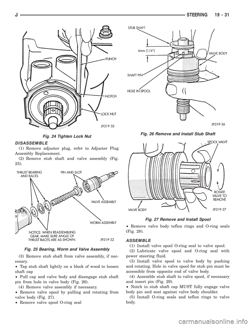
(1) Remove adjuster plug, refer to Adjuster Plug
Assembly Replacement.
(2) Remove stub shaft and valve assembly (Fig.
25).
(3) Remove stub shaft from valve assembly, if nec-
essary.
²Tap stub shaft lightly on a block of wood to loosen
shaft cap
²Pull cap and valve body and disengage stub shaft
pin from hole in valve body (Fig. 26).
(4) Remove valve assembly if necessary.
²Remove valve spool by pulling and rotating from
valve body (Fig. 27).
²Remove valve spool O-ring seal²Remove valve body teflon rings and O-ring seals
(Fig. 28).
ASSEMBLE
(1) Install valve spool O-ring seal to valve spool.
(2) Lubricate valve spool and O-ring seal with
power steering fluid.
(3) Install valve spool to valve body by pushing
and rotating. Hole in valve spool for stub pin must be
accessible from opposite end of valve body.
(4) Assemble stub shaft to valve spool, if necessary
and insert pin (Fig. 29).
²Notch in stub shaft cap MUST fully engage valve
body pin and seat against valve body shoulder.
(5) Install O-ring seals and teflon rings to valve
body.
Fig. 24 Tighten Lock Nut
Fig. 25 Bearing, Worm and Valve Assembly
Fig. 26 Remove and Install Stub Shaft
Fig. 27 Remove and Install Spool
JSTEERING 19 - 31
Page 1332 of 2198
CLEAN AND INSPECTION
(1) Wash all components in clean solvent and dry
with compressed air.
(2) Check for scores, nicks or burrs on the rack pis-
ton finished surface. Slight wear is normal on the
worm gear surfaces.
ASSEMBLE
(1) Install O-ring seal and teflon ring and lubricate
with power steering fluid.
(2) Install worm shaft to rack piston outside of
housing. Fully seat worm shaft to rack piston and
align worm shaft spiral groove with rack piston ball
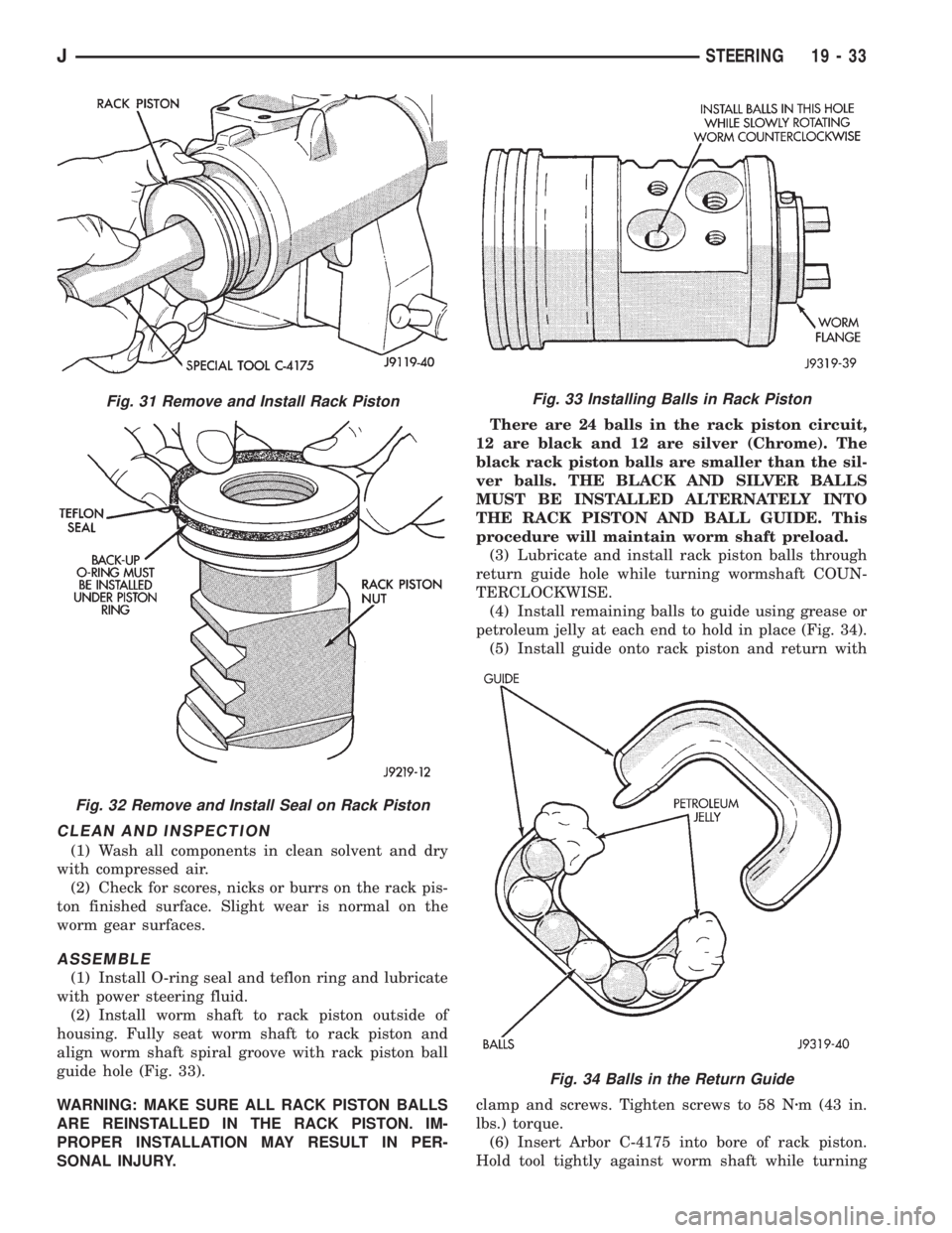
guide hole (Fig. 33).
WARNING: MAKE SURE ALL RACK PISTON BALLS
ARE REINSTALLED IN THE RACK PISTON. IM-
PROPER INSTALLATION MAY RESULT IN PER-
SONAL INJURY.There are 24 balls in the rack piston circuit,
12 are black and 12 are silver (Chrome). The
black rack piston balls are smaller than the sil-
ver balls. THE BLACK AND SILVER BALLS
MUST BE INSTALLED ALTERNATELY INTO
THE RACK PISTON AND BALL GUIDE. This
procedure will maintain worm shaft preload.
(3) Lubricate and install rack piston balls through
return guide hole while turning wormshaft COUN-
TERCLOCKWISE.
(4) Install remaining balls to guide using grease or
petroleum jelly at each end to hold in place (Fig. 34).
(5) Install guide onto rack piston and return with
clamp and screws. Tighten screws to 58 Nzm (43 in.
lbs.) torque.
(6) Insert Arbor C-4175 into bore of rack piston.
Hold tool tightly against worm shaft while turning
Fig. 31 Remove and Install Rack Piston
Fig. 32 Remove and Install Seal on Rack Piston
Fig. 33 Installing Balls in Rack Piston
Fig. 34 Balls in the Return Guide
JSTEERING 19 - 33
Page 1333 of 2198
the stub shaft COUNTERCLOCKWISE.
²The rack piston will be forced onto the tool and
hold the rack piston balls in place.
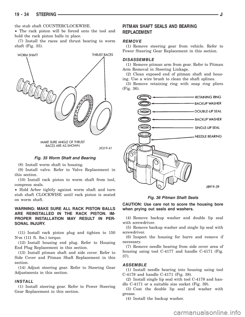
(7) Install the races and thrust bearing to worm
shaft (Fig. 35).
(8) Install worm shaft to housing.
(9) Install valve. Refer to Valve Replacement in
this section.
(10) Install rack piston to worm shaft from tool,
compress seals.
²Hold Arbor tightly against worm shaft and turn
stub shaft CLOCKWISE until rack piston is seated
on worm shaft.
WARNING: MAKE SURE ALL RACK PISTON BALLS
ARE REINSTALLED IN THE RACK PISTON. IM-
PROPER INSTALLATION MAY RESULT IN PER-
SONAL INJURY.
(11) Install rack piston plug and tighten to 150
Nzm (111 ft. lbs.) torque.
(12) Install housing end plug. Refer to Housing
End Plug Replacement in this section.
(13) Install pitman shaft and side cover. Refer to
Side Cover and Pitman Shaft Replacement in this
section.
(14) Adjust steering gear. Refer to Steering Gear
Adjustments in this section.
INSTALL
(1) Install steering gear. Refer to Power Steering
Gear Replacement in this section.
PITMAN SHAFT SEALS AND BEARING
REPLACEMENT
REMOVE
(1) Remove steering gear from vehicle. Refer to
Power Steering Gear Replacement in this section.
DISASSEMBLE
(1) Remove pitman arm from gear. Refer to Pitman
Arm Removal in Steering Linkage.
(2) Clean exposed end of pitman shaft and hous-
ing. Use a wire brush to clean the shaft splines.
(3) Remove retaining ring with snap ring pliers
(Fig. 36).
CAUTION: Use care not to score the housing bore
when prying out seals and washers.
(4) Remove backup washer and double lip seal
with screwdriver.
(5) Remove backup washer and single lip seal with
screwdriver.
(6) Inspect the housing for burrs and remove if
necessary.
(7) Remove needle bearing from side cover area of
housing using tool C-4177 and handle C-4171 (Fig.
37).
ASSEMBLE
(1) Install needle bearing into housing using tool
C-4178 and handle C-4171 (Fig. 38).
(2) Install single lip seal with tool C-4178 and han-
dle C-4171 or a suitable size socket (Fig. 39).
(3) Coat the double lip seal and washer with
grease.
(4) Install the backup washer.
Fig. 35 Worm Shaft and Bearing
Fig. 36 Pitman Shaft Seals
19 - 34 STEERINGJ
Page 1341 of 2198
(6) Lubricate the wormshaft threads with chassis
lubricant. Rotate the shaft to move it in and out of
the ball nut and distribute the lubricant.
(7) Lubricate the wormshaft upper bearing with
chassis lubricant and install it on the wormshaft.
WORMSHAFT BEARING ADJUSTMENT CAP
DISASSEMBLY
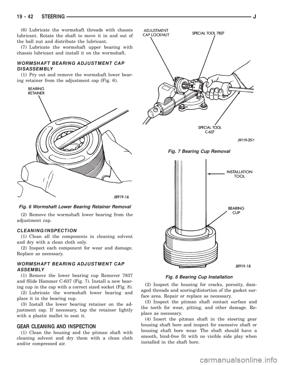
(1) Pry out and remove the wormshaft lower bear-
ing retainer from the adjustment cap (Fig. 6).
(2) Remove the wormshaft lower bearing from the
adjustment cap.
CLEANING/INSPECTION
(1) Clean all the components in cleaning solvent
and dry with a clean cloth only.
(2) Inspect each component for wear and damage.
Replace as necessary.
WORMSHAFT BEARING ADJUSTMENT CAP
ASSEMBLY
(1) Remove the lower bearing cup Remover 7837
and Slide Hammer C-637 (Fig. 7). Install a new bear-
ing cup in the cap with a correct sized socket (Fig. 8).
(2) Lubricate the wormshaft lower bearing and
place it in the bearing cup.
(3) Install the lower bearing retainer on the ad-
justment cap. If necessary, tap the retainer lightly
with a plastic mallet to seat it.
GEAR CLEANING AND INSPECTION
(1) Clean the housing and the pitman shaft with
cleaning solvent and dry them with a clean cloth
and/or compressed air.(2) Inspect the housing for cracks, porosity, dam-
aged threads and scoring/distortion of the gasket sur-
face area. Repair or replace as necessary.
(3) Inspect the pitman shaft contact surface and
the teeth for wear, pitting, and other damage. Re-
place as necessary.
(4) Insert the pitman shaft in the steering gear
housing shaft bore and inspect for excessive shaft or
housing shaft bore wear. The shaft should have a
smooth, bind-free fit with no visible side play when
installed in the shaft bore.
Fig. 6 Wormshaft Lower Bearing Retainer Removal
Fig. 7 Bearing Cup Removal
X
Fig. 8 Bearing Cup Installation
19 - 42 STEERINGJ
Page 1353 of 2198
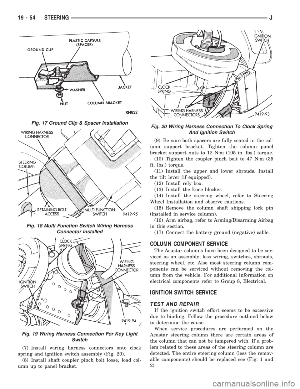
(7) Install wiring harness connectors onto clock
spring and ignition switch assembly (Fig. 20).
(8) Install shaft coupler pinch bolt loose, load col-
umn up to panel bracket.(9) Be sure both spacers are fully seated in the col-
umn support bracket. Tighten the column panel
bracket support nuts to 12 Nzm (105 in. lbs.) torque.
(10) Tighten the coupler pinch bolt to 47 Nzm (35
ft. lbs.) torque.
(11) Install the upper and lower shrouds. Install
the tilt lever (if equipped).
(12) Install rely box.
(13) Install the knee blocker.
(14) Install the steering wheel, refer to Steering
Wheel Installation and observe cautions.
(15) Remove the column shaft shipping lock pin
(installed in service column).
(16) Arm airbag, refer to Arming/Disarming Airbag
in this section.
(17) Connect the battery ground (negative) cable.
COLUMN COMPONENT SERVICE
The Acustar columns have been designed to be ser-
viced as an assembly; less wiring, switches, shrouds,
steering wheel, etc. Also most steering column com-
ponents can be serviced without removing the col-
umn from the vehicle. For additional information on
electrical components refer to Group 8, Electrical.
IGNITION SWITCH SERVICE
TEST AND REPAIR
If the ignition switch effort seems to be excessive
due to binding. Follow the procedure outlined below
to determine the cause.
When service procedures are performed on the
Acustar steering column there are certain areas of
the column that can not be tampered with. If a prob-
lem related to these areas of the steering column are
detected. The entire steering column (less the remov-
able components) should be replaced see (Fig. 1 and
2).
Fig. 17 Ground Clip & Spacer Installation
Fig. 18 Multi Function Switch Wiring Harness
Connector Installed
Fig. 19 Wiring Harness Connection For Key Light
Switch
Fig. 20 Wiring Harness Connection To Clock Spring
And Ignition Switch
19 - 54 STEERINGJ
Page 1363 of 2198
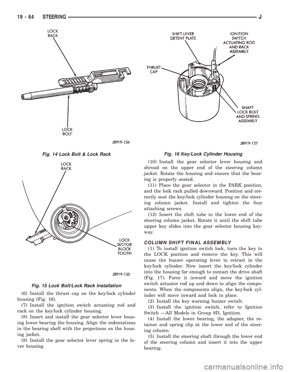
(6) Install the thrust cap on the key/lock cylinder
housing (Fig. 16).
(7) Install the ignition switch actuating rod and
rack on the key/lock cylinder housing.
(8) Insert and install the gear selector lever hous-
ing lower bearing the housing. Align the indentations
in the bearing shell with the projections on the hous-
ing jacket.
(9) Install the gear selector lever spring in the le-
ver housing.(10) Install the gear selector lever housing and
shroud on the upper end of the steering column
jacket. Rotate the housing and ensure that the bear-
ing is properly seated.
(11) Place the gear selector in the PARK position,
and the lock rack pulled downward. Position and cor-
rectly seat the key/lock cylinder housing on the steer-
ing column jacket. Install and tighten the four
attaching screws.
(12) Insert the shift tube in the lower end of the
steering column jacket. Rotate it until the shift tube
upper key slides into the gear selector housing key-
way.
COLUMN SHIFT FINAL ASSEMBLY
(1) To install ignition switch lock, turn the key to
the LOCK position and remove the key. This will
cause the buzzer operating lever to retract in the
key/lock cylinder. Now insert the key/lock cylinder
into the housing far enough to contact the drive shaft
(Fig. 17). Force it inward and move the ignition
switch actuator rod up and down to align the compo-
nents. When the components align, the key/lock cyl-
inder will move inward and lock in place.
(2) Install the key warning buzzer switch.
(3) Install the ignition switch, refer to Ignition
Switch ÐAll Models in Group 8D, Ignition.
(4) Install the lower bearing, the adapter, the re-
tainer and spring clip at the lower end of the steer-
ing column.
(5) Install the steering shaft through the lower end
of the steering column and insert it into the upper
bearing.
Fig. 14 Lock Bolt & Lock Rack
Fig. 15 Lock Bolt/Lock Rack Installation
Fig. 16 Key/Lock Cylinder Housing
19 - 64 STEERINGJ
Page 1364 of 2198
(6) Position the turn signal switch and wire har-
ness in the cylinder housing. Fold the wires against
the connector. Route the connector down through the
steering column jacket.
(7) Install the windshield wiper wire harness and
switch. Route the wire harness down through steer-
ing column jacket.
(8) Align the turn signal switch in the housing and
secure the switch with the attaching screws. Tighten
the screws to 4 Nzm (35 in. lbs.) torque.
(9) Install the dimmer switch actuator arm.
Tighten the attaching screws to 4 Nzm (35 in. lbs.)
torque.
(10) If equipped, install the cruise control wire har-
ness. Install the turn signal stalk by pushing it
straight into the column.
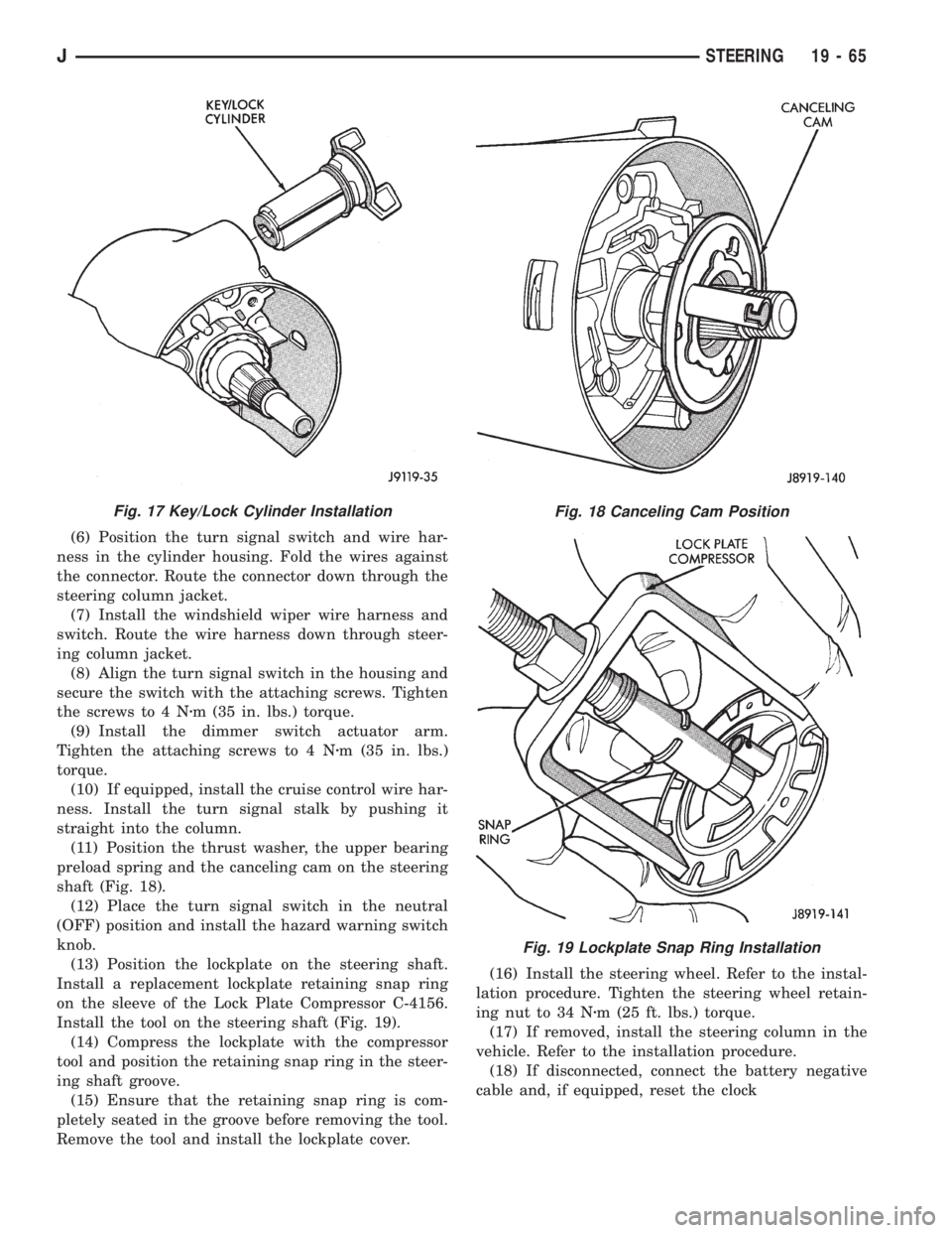
(11) Position the thrust washer, the upper bearing
preload spring and the canceling cam on the steering
shaft (Fig. 18).
(12) Place the turn signal switch in the neutral
(OFF) position and install the hazard warning switch
knob.
(13) Position the lockplate on the steering shaft.
Install a replacement lockplate retaining snap ring
on the sleeve of the Lock Plate Compressor C-4156.
Install the tool on the steering shaft (Fig. 19).
(14) Compress the lockplate with the compressor
tool and position the retaining snap ring in the steer-
ing shaft groove.
(15) Ensure that the retaining snap ring is com-
pletely seated in the groove before removing the tool.
Remove the tool and install the lockplate cover.(16) Install the steering wheel. Refer to the instal-
lation procedure. Tighten the steering wheel retain-
ing nut to 34 Nzm (25 ft. lbs.) torque.
(17) If removed, install the steering column in the
vehicle. Refer to the installation procedure.
(18) If disconnected, connect the battery negative
cable and, if equipped, reset the clock
Fig. 17 Key/Lock Cylinder InstallationFig. 18 Canceling Cam Position
Fig. 19 Lockplate Snap Ring Installation
JSTEERING 19 - 65
Page 1366 of 2198
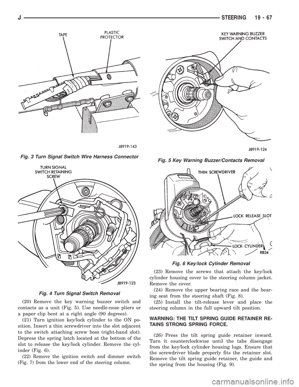
(20) Remove the key warning buzzer switch and
contacts as a unit (Fig. 5). Use needle-nose pliers or
a paper clip bent at a right angle (90 degrees).
(21) Turn ignition key/lock cylinder to the ON po-
sition. Insert a thin screwdriver into the slot adjacent
to the switch attaching screw boss (right-hand slot).
Depress the spring latch located at the bottom of the
slot to release the key/lock cylinder. Remove the cyl-
inder (Fig. 6).
(22) Remove the ignition switch and dimmer switch
(Fig. 7) from the lower end of the steering column.
(23) Remove the screws that attach the key/lock
cylinder housing cover to the steering column jacket.
Remove the cover.
(24) Remove the upper bearing race and the bear-
ing seat from the steering shaft (Fig. 8).
(25) Install the tilt-release lever and place the
steering column in the full upward tilt position.
WARNING: THE TILT SPRING GUIDE RETAINER RE-
TAINS STRONG SPRING FORCE.
(26) Press the tilt spring guide retainer inward.
Turn it counterclockwise until the tabs disengage
from the key/lock cylinder housing lugs. Ensure that
the screwdriver blade properly fits the retainer slot.
Remove the tilt spring guide retainer, the guide and
the spring from the housing (Fig. 9).
Fig. 3 Turn Signal Switch Wire Harness Connector
Fig. 4 Turn Signal Switch Removal
Fig. 5 Key Warning Buzzer/Contacts Removal
Fig. 6 Key/lock Cylinder Removal
JSTEERING 19 - 67