Page 1507 of 1771
Heater Valve
Test
1. Disconnect the 2P connector from the heater valve
control solenoid valve.
2. Check for continuity between the No. 1 and No. 2
terminals of the heater valve control solenoid valve.
HEATER VALVE CONTROL
SOLENOID VALVE
3. Disconnect the #2 vacuum hose from the intake
manifold, then connect a vacuum pump to the #2
vacuum hose.
HEATER VALVE CONTROL
SOLENOID VALVE
#2 VACUUM HOSE
HEATER VALVE
4. Connect battery power to the No. 2 terminal of the
heater valve control solenoid valve, and ground the
No. 1 terminal.
5. Check that the rod of the heater valve is pulled
toward the diaphragm when vacuum is applied to
the heater valve control solenoid with a vacuum
pump.
6. Check that the rod is returned to the original posi-
tion when power is disconnected.
RODProCarManuals.com
Page 1508 of 1771
Evaporator
Replacemen t
1. Recove r th e refrigeran t wit h a Recovery/Recycling /
Chargin g Syste m (se e pag e 22-71 ).
2 . Remov e th e dashboar d lowe r cover , th e kne e bol -
ste r an d th e glov e bo x (se e sectio n 20 ).
3 . Remov e th e EC M (se e sectio n 11 ).
4 . Remov e th e AB S contro l uni t an d th e radiato r fa n
contro l modul e togethe r wit h th e bracket , the n
remov e th e TC M (se e sectio n 14 ). Remov e th e secu -
rity contro l unit .
5. Disconnec t th e connector s fro m th e powe r transis -
tor , blowe r moto r hig h relay , evaporato r tempera -
tur e sensor , blowe r moto r an d th e heate r sub-har -
ness , the n remov e th e blowe r moto r an d heate r sub -
harnes s connector s fro m th e brackets . Disconnec t
th e passenger' s airba g harnes s clip .
BLOWE R MOTO R HIG H RELA Y
EVAPORATO RTEMPERATUR ESENSORCONNECTO R
BLOWER MOTO R CONNECTO R
POWER TRANSISTO R
HEATER SUB-HARNES SCONNECTOR
ProCarManuals.com
Page 1513 of 1771

Heater Uni t
Replacemen t
SRS component s ar e locate d i n thi s area . Revie w th e
SR S componen t locations , precautions , an d procedure s
i n th e SR S ( sectio n 24 ) befor e performin g repair s o r ser -
vice .
1 . Disconnec t th e negativ e cabl e fro m th e battery .
2 . Whe n th e engin e i s cool , drai n th e engin e coolan t
fro m th e radiato r (se e sectio n 10 ).
D o no t remov e th e radiato r ca p whe n
th e engin e i s hot ; th e engin e coolan t i s unde r pres -
sur e an d coul d severel y scal d you .
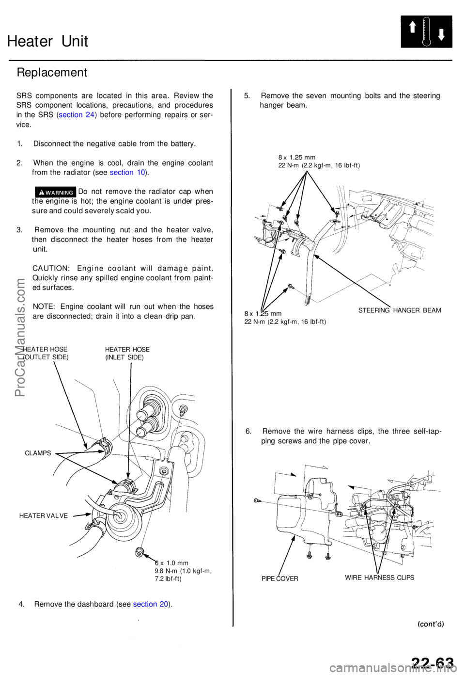
3 . Remov e th e mountin g nu t an d th e heate r valve ,
the n disconnec t th e heate r hose s fro m th e heate r
unit.
CAUTION : Engin e coolan t wil l damag e paint .
Quickl y rins e an y spille d engin e coolan t fro m paint -
e d surfaces .
NOTE : Engin e coolan t wil l ru n ou t whe n th e hose s
ar e disconnected ; drai n i t int o a clea n dri p pan .
HEATE R HOS E
(OUTLE T SIDE ) HEATE
R HOS E
(INLE T SIDE )
CLAMP S
HEATE R VALV E
6 x 1. 0 m m9.8 N- m (1. 0 kgf-m ,
7. 2 Ibf-ft )
4. Remov e th e dashboar d (se e sectio n 20 ). 5
. Remov e th e seve n mountin g bolt s an d th e steerin g
hange r beam .
8 x 1.2 5 mm22 N- m (2. 2 kgf-m , 1 6 Ibf-ft )
8 x 1.2 5 mm22 N- m (2. 2 kgf-m , 1 6 Ibf-ft ) STEERIN
G HANGE R BEA M
6. Remov e th e wir e harnes s clips , th e thre e self-tap -
pin g screw s an d th e pip e cover .
PIPE COVE R WIR
E HARNES S CLIP S
ProCarManuals.com
Page 1514 of 1771

Heater Uni t
Replacemen t (cont'd )
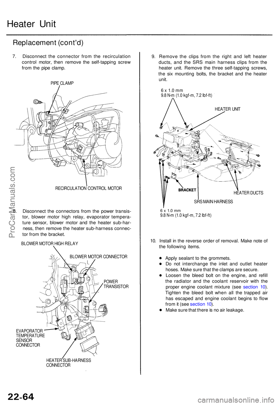
7. Disconnec t th e connecto r fro m th e recirculatio n
contro l motor , the n remov e th e self-tappin g scre w
fro m th e pip e clamp .
PIPE CLAM P
RECIRCULATIO N CONTRO L MOTO R
8. Disconnec t th e connector s fro m th e powe r transis -
tor , blowe r moto r hig h relay , evaporato r tempera -
tur e sensor , blowe r moto r an d th e heate r sub-har -
ness , the n remov e th e heate r sub-harnes s connec -
to r fro m th e bracket .
BLOWER MOTO R HIG H RELA Y
BLOWE R MOTO R CONNECTO R
POWERTRANSISTO R
EVAPORATO RTEMPERATUR ESENSORCONNECTO R
HEATE R SUB-HARNES S
CONNECTO R
9. Remov e th e clip s fro m th e righ t an d lef t heate r
ducts , an d th e SR S mai n harnes s clip s fro m th e
heate r unit . Remov e th e thre e self-tappin g screws,
th e si x mountin g bolts , th e bracke t an d th e heate r
unit .
6 x 1. 0 m m9.8 N- m (1. 0 kgf-m , 7. 2 Ibf-ft )
HEATE R UNI T
HEATE R DUCT S
SRS MAI N HARNES S
6 x 1. 0 m m9.8 N- m (1. 0 kgf-m , 7. 2 Ibf-ft )
10. Instal l i n th e revers e orde r o f removal . Mak e not e o f
th e followin g items .
Appl y sealan t t o th e grommets .
D o no t interchang e th e inle t an d outle t heate r
hoses . Mak e sur e tha t th e clamp s ar e secure .
Loose n th e blee d bol t o n th e engine , an d refil l
th e radiato r an d th e coolan t reservoi r wit h th e
prope r engin e coolan t mixtur e (se e sectio n 10 ).
Tighte n th e blee d bol t whe n al l th e trappe d ai r
ha s escape d an d engin e coolan t begin s t o flo w
fro m it (se e sectio n 10 ).
Mak e sur e tha t ther e is n o ai r leakage .
ProCarManuals.com
Page 1515 of 1771

Heater Cor e Replacemen t
1. Remov e th e heate r uni t (se e pag e 22-63 ).
2 . Remov e th e mod e contro l moto r (se e pag e 22-51 ).
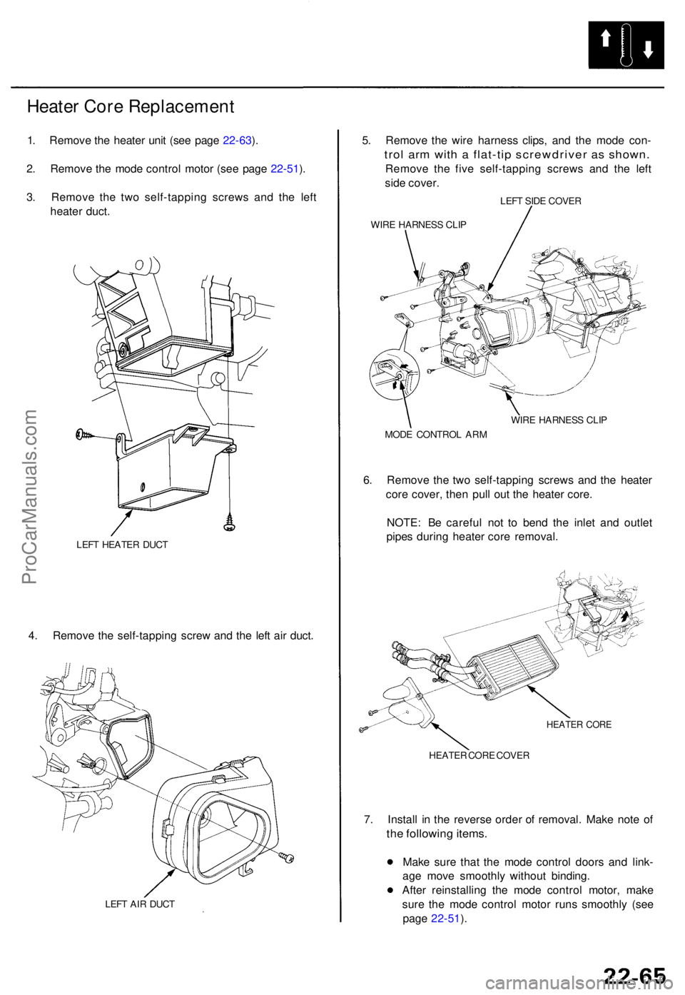
3 . Remov e th e tw o self-tappin g screw s an d th e lef t
heate r duct .
LEFT HEATE R DUC T
4. Remov e th e self-tappin g scre w an d th e lef t ai r duct .
LEFT AI R DUC T
5. Remov e th e wir e harnes s clips , an d th e mod e con -
trol ar m wit h a flat-ti p screwdrive r a s shown .
Remove th e fiv e self-tappin g screw s an d th e lef t
sid e cover .
LEFT SID E COVE R
WIR E HARNES S CLI P
WIRE HARNES S CLI P
MOD E CONTRO L AR M
6. Remov e th e tw o self-tappin g screw s an d th e heate r
cor e cover , the n pul l ou t th e heate r core .
NOTE : B e carefu l no t t o ben d th e inle t an d outle t
pipe s durin g heate r cor e removal .
HEATER COR E
HEATE R COR E COVE R
7. Instal l i n th e revers e orde r o f removal . Mak e not e o f
the followin g items .
Make sur e tha t th e mod e contro l door s an d link -
ag e mov e smoothl y withou t binding .
Afte r reinstallin g th e mod e contro l motor , mak e
sur e th e mod e contro l moto r run s smoothl y (se e
pag e 22-51 ).
ProCarManuals.com
Page 1517 of 1771

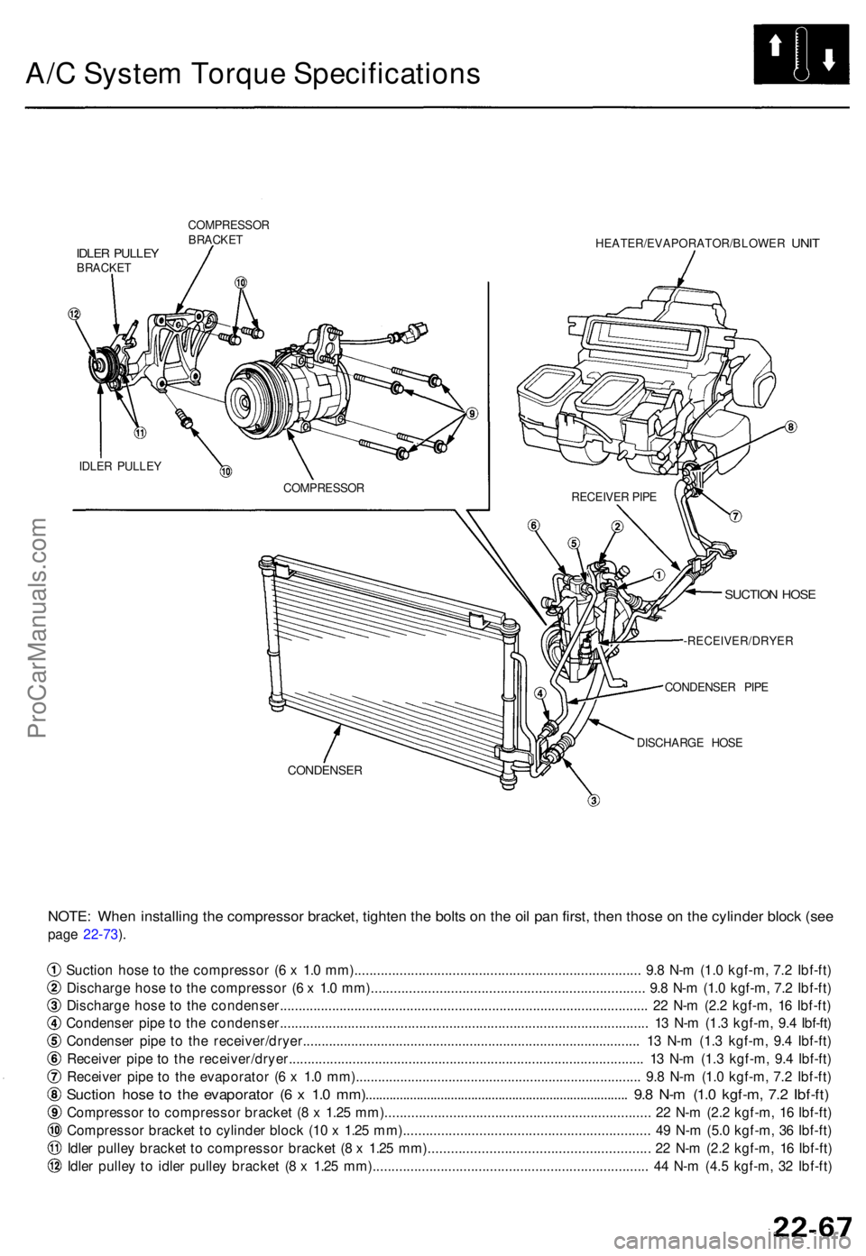
A/C Syste m Torqu e Specification s
COMPRESSO R
BRACKE T
IDLER PULLE YBRACKE T HEATER/EVAPORATOR/BLOWE
R
UNIT
SUCTIO N HOS E
-RECEIVER/DRYE R
CONDENSE R PIP E
DISCHARG E HOS E
CONDENSE R
NOTE: Whe n installin g th e compresso r bracket , tighte n th e bolt s o n th e oi l pa n first , the n thos e o n th e cylinde r bloc k (se e
page 22-73 ).
Suctio n hos e t o th e compresso r ( 6 x 1. 0 mm)...................................................................\
........ . 9. 8 N- m (1. 0 kgf-m , 7. 2 Ibf-ft )
Discharg e hos e t o th e compresso r ( 6 x 1. 0 mm)...................................................................\
.... . 9. 8 N- m (1. 0 kgf-m , 7. 2 Ibf-ft )
Discharg e hos e t o th e condenser..............................................................\
.................................... . 2 2 N- m (2. 2 kgf-m , 1 6 Ibf-ft )
Condense r pip e t o th e condenser..............................................................\
................................... . 1 3 N- m (1. 3 kgf-m , 9. 4 Ibf-ft )
Condense r pip e t o th e receiver/dryer.........................................................\
................................. . 1 3 N- m (1. 3 kgf-m , 9. 4 Ibf-ft )
Receive r pip e t o th e receiver/dryer.........................................................\
..................................... . 1 3 N- m (1. 3 kgf-m , 9. 4 Ibf-ft )
Receive r pip e t o th e evaporato r ( 6 x 1. 0 mm)...................................................................\
......... . 9. 8 N- m (1. 0 kgf-m , 7. 2 Ibf-ft )
Suctio n hos e t o th e evaporato r ( 6 x 1. 0 mm)...................................................................\
......... . 9. 8 N- m (1. 0 kgf-m , 7. 2 Ibf-ft )
Compresso r t o compresso r bracke t ( 8 x 1.2 5 mm)...................................................................\
.. . 2 2 N- m (2. 2 kgf-m , 1 6 Ibf-ft )
Compresso r bracke t t o cylinde r bloc k (1 0 x 1.2 5 mm)................................................................ . 4 9 N- m (5. 0 kgf-m , 3 6 Ibf-ft )
Idle r pulle y bracke t t o compresso r bracke t ( 8 x 1.2 5 mm)......................................................... . 2 2 N- m (2. 2 kgf-m , 1 6 Ibf-ft )
Idle r pulle y t o idle r pulle y bracke t ( 8 x 1.2 5 mm)...................................................................\
..... . 4 4 N- m (4. 5 kgf-m , 3 2 Ibf-ft )
IDLER PULLE Y
COMPRESSOR
RECEIVER PIP E
ProCarManuals.com
Page:
< prev 1-8 9-16 17-24