Page 629 of 1771
Troubleshooting
NOTE: The numbers in the table show the troubleshooting sequence.
Switch Replacement
1. Remove the center console.
2. Remove the heater switch from the center console.ProCarManuals.com
Page 630 of 1771
Seat Heaters
Switch Test
1. Remove the switch from the center console.
Heater Test
1. Disconnect the 6P (Driver's seat) or 3P (Front pas-
senger's seat) connector as shown below.
2. Check for continuity between the No. 3 and No. 4
(Driver's seat) or No. 2 (Front passenger's seat) ter-
minals.
There should be continuity.
2. Check for continuity between the terminals in each
switch position according to the table.ProCarManuals.com
Page 751 of 1771

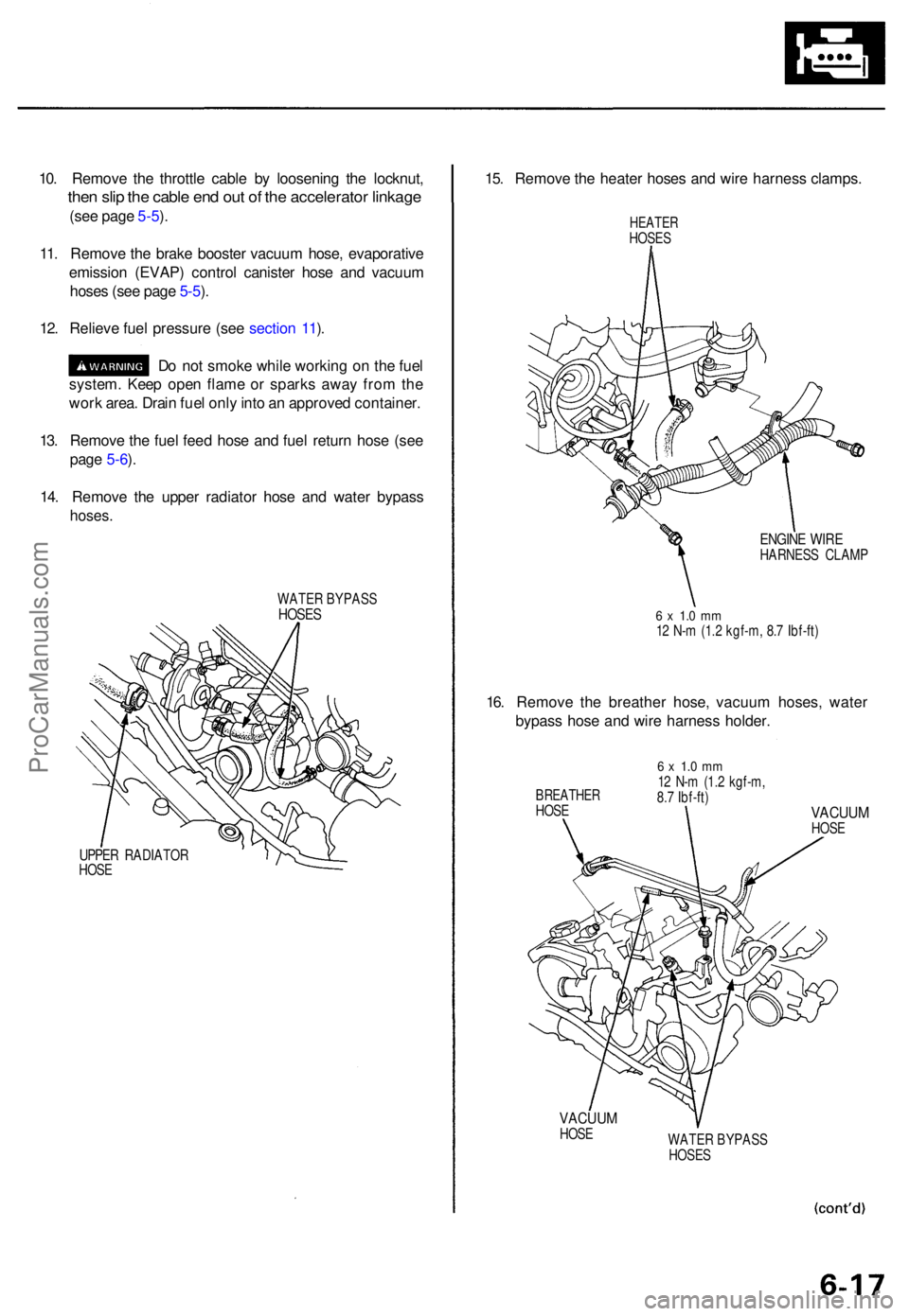
10. Remov e th e throttl e cabl e b y loosenin g th e locknut ,
then sli p th e cabl e en d ou t o f th e accelerato r linkag e
(see pag e 5-5 ).
11 . Remov e th e brak e booste r vacuu m hose , evaporativ e
emissio n (EVAP ) contro l caniste r hos e an d vacuu m
hose s (se e pag e 5-5 ).
12 . Reliev e fue l pressur e (se e sectio n 11 ).
D o no t smok e whil e workin g o n th e fue l
system . Kee p ope n flam e o r spark s awa y fro m th e
wor k area . Drai n fue l onl y int o a n approve d container .
13 . Remov e th e fue l fee d hos e an d fue l retur n hos e (se e
pag e 5-6 ).
14 . Remov e th e uppe r radiato r hos e an d wate r bypas s
hoses.
WATE R BYPAS SHOSES
UPPER RADIATO R
HOS E
15. Remov e th e heate r hose s an d wir e harnes s clamps .
HEATERHOSES
ENGIN E WIR EHARNES S CLAM P
6 x 1. 0 m m12 N- m (1. 2 kgf-m , 8. 7 Ibf-ft )
16. Remov e th e breathe r hose , vacuu m hoses , wate r
bypas s hos e an d wir e harnes s holder .
BREATHE RHOSE
6 x 1. 0 m m12 N- m (1. 2 kgf-m ,
8. 7 Ibf-ft )
VACUU MHOSE
VACUU MHOSE
WATER BYPAS S
HOSE S
ProCarManuals.com
Page 877 of 1771

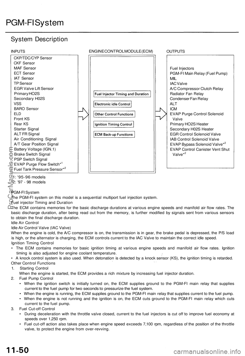
PGM-FI System
System Description
INPUTS
ENGINE CONTROL MODULE (ECM)
OUTPUTS
Fuel Injectors
PGM-FI Main Relay (Fuel Pump)
MIL
IAC Valve
A/C Compressor Clutch Relay
Radiator Fan Relay
Condenser Fan Relay
ALT
ICM
EVAP Purge Control Solenoid
Valve
Primary HO2S Heater
Secondary H02S Heater
EGR Control Solenoid Valve
IAB Control Solenoid Valve
EVAP Bypass Solenoid Valve*2
EVAP Control Canister Vent Shut
Valve*2
*1: '95-96 models
*2: '97 - 98 models
PGM-FI System
The PGM-FI system on this model is a sequential multiport fuel injection system.
Fuel injector Timing and Duration
The ECM contains memories for the basic discharge durations at various engine speeds and manifold air flow rates. The
basic discharge duration, after being read out from the memory, is further modified by signals sent from various sensors
to obtain the final discharge duration.
Idle Air Control
Idle Air Control Valve (IAC Valve)
When the engine is cold, the A/C compressor is on, the transmission is in gear, the brake pedal is depressed, the P/S load
is high, or the alternator is charging, the ECM controls current to the IAC Valve to maintain the correct idle speed.
Ignition Timing Control
• The ECM contains memories for basic ignition timing at various engine speeds and manifold air flow rates. Ignition
timing is also adjusted for engine coolant temperature.
• A knock control system is also used. When detonation is detected by a knock sensor (KS), the ignition timing is retarded.
Other Control Functions
1. Starting Control
When the engine is started, the ECM provides a rich mixture by increasing fuel injector duration.
2. Fuel Pump Control
• When the ignition switch is initially turned on, the ECM supplies ground to the PGM-FI main relay that supplies
current to the fuel pump for two seconds to pressurize the fuel system.
• When the engine is running, the ECM supplies ground to the PGM-FI main relay that supplies current to the fuel pump.
• When the engine is not running and the ignition is on, the ECM cuts ground to the PGM-FI main relay which cuts
current to the fuel pump.
3. Fuel Cut-off Control
• During deceleration with the throttle valve closed, current to the fuel injectors is cut off to improve fuel economy at
speeds over 1,250 rpm.
• Fuel cut-off action also takes place when engine speed exceeds 7,100 rpm, regardless of the position of the throttle
valve, to protect the engine from over-revving.
CKP/TDC/CYP Sensor
CKF Sensor
MAF Sensor
ECT Sensor
IAT Sensor
TP Sensor
EGR Valve Lift Sensor
Primary HO2S
Secondary H02S
VSS
BARO Sensor
ELD
Front KS
Rear KS
Starter Signal
ALT FR Signal
Air Conditioning Signal
A/T Gear Position Signal
Battery Voltage (IGN.1)
Brake Switch Signal
PSP Switch Signal
EVAP Purge Flow Switch*1
Fuel Tank Pressure Sensor*2ProCarManuals.com
Page 1296 of 1771
GAUGE ASSEMBLY
UNDER-HOOD FUSE/RELAY BOX
ABS INDICATOR LIGHT
BATTERY
(100 A) FUSE
IG (50 A) FUSE
STOP/ HORN
(20 A) FUSE
UNDER-DASH FUSE/RELAY BOX
UNDER-HOOD ABS FUSE/RELAY BOX
HEATER
CONTROL RELAY
(7.5 A) FUSE
BACK-UP LIGHTS/
METER LIGHTS
(SUN ROOF)
(10 A) FUSE
ECU (ECM)/
CRUISE CONTROL/
EAT ECU
(15 A) FUSE
ABS MOTOR (40 A) FUSE
ABS B1 (20 A) FUSE
ABS B2 (15 A) FUSE
ABS PUMP MOTOR RELAY
UNDER-DASH RELAY BOX
ABS UNIT (10 A) FUSE
REAR FAIL-SAFE RELAY
FRONT FAIL-SAFE RELAYProCarManuals.com
Page 1322 of 1771
ABS INDICATOR LIGHT
BATTERY
(100 A) FUSE
STOP/ HORN
(20 A) FUSE
IG (50 A) FUSE
UNDER-DASH FUSE/RELAY BOX
UNDER-HOOD ABS FUSE/RELAY BOX
HEATER
CONTROL RELAY
(7.5 A) FUSE
BACK-UP LIGHTS/
METER LIGHTS
(SUN ROOF)
(10 A) FUSE
ECU (ECM)/
CRUISE CONTROL/
EAT ECU
(15 A) FUSE
ABS MOTOR (30 A) FUSE
ABS B1 (20 A) FUSE
UNDER-DASH RELAY BOX
ABS PUMP MOTOR RELAY
ABS UNIT (7.5 A) FUSE
FAIL-SAFE RELAYProCarManuals.com
Page 1490 of 1771
Illustrated Inde x
HEATER/EVAPORATOR/BLOWE R UNITHEATE R UNI T
Replacement , pag e 22-6 3
Heate r Cor e Replacement , pag e 22-6 5
EVAPORATO RReplacement, pag e 22-5 8
Overhaul , pag e 22-6 0
BLOWE R UNI T
Replacement , pag e 22-6 1
Overhaul , pag e 22-6 2
SERVIC E VALV E
(HIGH-PRESSUR E SIDE )
EXPANSION VALV E
Replacement , pag e 22-5 8
CONDENSE R
Replacement , pag e 22-7 9
A/ C PRESSUR E SWITC H
Whe n th e refrigeran t pressur e i s belo w 20 0 kP a (2. 0 kgf/cm
2,
2 8 psi ) du e t o refrigeran t leakag e o r abov e 3,20 0 kP a (3 2 kgf/cm2,45 5 psi ) du e to refrigeran t blockage , th e A/ C pressur e switc hopens th e circui t t o th e A/ C switc h an d stop s th e ai r conditionin gto protec t th e compressor .
SERVICE VALV E
(LOW-PRESSUR E SIDE )
COMPRESSO RReplacement, pag e 22-7 2
Clutc h Inspection , pag e 22-7 5
Clutc h Overhaul , pag e 22-7 6
Relie f Valv e Replacement , pag e 22-7 7
RECEIVER/DRYE R
ProCarManuals.com
Page 1493 of 1771

Description
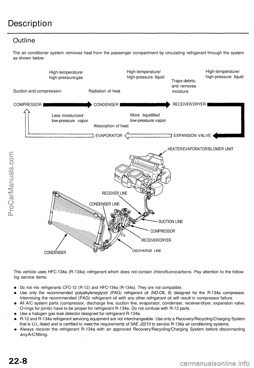
Outline
The air conditioner system removes heat from the passenger compartment by circulating refrigerant through the system
as shown below.
High-temperature/
high-pressure gas
Suction and compression
Radiation of heat
High-temperature/
high-pressure liquid
Traps debris,
and removes
moisture
High-temperature/
high-pressure liquid
COMPRESSOR
Less moisturized
low-pressure vapor
CONDENSER
Absorption of heat
EVAPORATOR
More liquidified
low-pressure vapor
RECEIVER/DRYER
EXPANSION VALVE
HEATER/EVAPORATOR/BLOWER
UNIT
CONDENSER
SUCTION LINE
COMPRESSOR
RECEIVER/DRYER
DISCHARGE LINE
This vehicle uses HFC-134a (R-134a) refrigerant which does not contain chlorofluorocarbons. Pay attention to the follow-
ing service items:
Do not mix refrigerants CFC-12 (R-12) and HFC-134a (R-134a). They are not compatible.
Use only the recommended polyalkyleneglycol (PAG) refrigerant oil (ND-OIL 8) designed for the R-134a compressor.
Intermixing the recommended (PAG) refrigerant oil with any other refrigerant oil will result in compressor failure.
All A/C system parts (compressor, discharge line, suction line, evaporator, condenser, receiver/dryer, expansion valve.
O-rings for joints) have to be proper for refrigerant R-134a. Do not confuse with R-12 parts.
Use a halogen gas leak detector designed for refrigerant R-134a.
R-12 and R-134a refrigerant servicing equipment are not interchangeable. Use only a Recovery/Recycling/Charging System
that is U.L.-listed and is certified to meet the requirements of SAE J2210 to service R-134a air conditioning systems.
Always recover the refrigerant R-134a with an approved Recovery/Recycling/Charging System before disconnecting
any A/C fitting.
RECEIVER LINE
CONDENSER LINEProCarManuals.com