1994 JEEP CHEROKEE heating
[x] Cancel search: heatingPage 1677 of 1784
SERVICE DIAGNOSISÐELECTRICAL
BLOWER CONTROLSÐXJ VEHICLES
DESCRIPTION
The blower motor delivers air to the inside of the
vehicle. Its speed is controlled by the blower switch
and the blower resistors. With the switch in LO, part
of the battery voltage is supplied to the motor
through all of the resistors. The motor runs slowly.
As the blower switch is moved to a higher speed, the
switch allows more voltage to be applied to the
blower motor, which will increase its speed. When
the switch is in HI, the blower resistors are bypassed
and battery voltage is applied directly to the blower
motor. The motor runs at the fastest speed in this
mode.
DIAGNOSIS
Refer to the Group 8W, Wiring Diagrams for com-
plete system schematic.
1. BLOWER MOTOR INOPERATIVE
²Remove and inspect fuse. If the fuse is blown, re-
place fuse.
2. BLOWER MOTOR INOPERATIVE (HI Posi-
tion)
Put the ignition switch in RUN, the select switch
in HEAT and the blower switch on HI.
²Blower motor connector (Terminal A) should be
battery voltage. If not go to next step.
²Blower motor connector (Terminal B) should be 0
ohms. If not, repair wire to ground.
²Blower switch connector (Terminal C) should be
battery voltage. If battery voltage replace blower
switch. If not, replace select switch.
3. BLOWER MOTOR INOPERATIVE (LO, M1
& M2 Positions)
Ignition switch in RUN, select switch in HEAT.
²Blower resistors connector (Terminal D) should be
battery voltage. If not, replace select switch.
²Blower resistors connector (Terminal C) should be
battery voltage. If not, replace blower switch.
²Blower resistors connector (Terminal A) should be
battery voltage. If not, replace blower switch.
²Blower resistors connector (Terminal B) should be
battery voltage. If not, replace blower resistor.
AIR CONDITIONING SYSTEMÐXJ VEHICLES
DESCRIPTION
The A/C Compressor Clutch is belt-driven by the
engine. A clutch, operated by a solenoid, automati-
cally turns the compressor on and off to control evap-
orator icing.
The A/C Compressor Clutch operation is controlled
by several components: the A/C Low-Pressure
Switch, Thermostat Switch, Fuel Pump Relay, A/C
Clutch Relay and the Engine Controller.The A/C low pressure switch opens when there is
not enough refrigerant in the system. When this hap-
pens, voltage is no longer present at the Engine Con-
troller. The Engine Controller will turn off the A/C
clutch relay. With the proper refrigerant level in the
system, the low pressure switch remains closed.
When the evaporator temperature is low enough to
ice the cooling coils, the thermostat switch opens.
The Engine Controller will turn off the A/C clutch.
The thermostat switch closes when the temperature
rises. The Engine Controller will then turn the A/C
clutch relay on again.
DIAGNOSIS
Refer to the Group 8W, Wiring Diagrams for com-
plete system schematic.
With engine running, Engine Controller may delay
A/C clutch up to 30 seconds.
1. A/C COMPRESSOR CLUTCH INOPERA-
TIVE
Clutch connector disconnected.
²Jumper fused test lead, battery to clutch connec-
tor, clutch should operate. If not, replace compressor
clutch assembly.
2. A/C LOW PRESSURE SWITCH
Ignition in RUN, A/C controls in MAX or NORM.
²Low pressure switch connector (Terminal A)
should be battery voltage. If not, repair open to select
switch.
²Low pressure switch connector (Terminal C)
should be battery voltage. If not, check switch resis-
tance and check freon pressure.
3. A/C CLUTCH RELAY
Engine RUNNING, A/C controls in MAX or
NORM.
²Relay connector Pin 4 to ground should be battery
voltage. If not, check fuse F6 in Power Distribution
Center.
²Ground A/C clutch relay (Terminal 5) should have
A/C compressor clutch engagement. If not, check En-
gine Controller Terminals 27, 28 and 34.
HEATING SYSTEMÐYJ VEHICLES
DESCRIPTION
The blower motor circuit begins at a 25 amp fuse
that receives its battery feed from the ignition
switch. From the fuse the circuit extends to a micro-
switch mounted on the heater control.
The micro-switch is normally closed is operated by
a cam on the heater control lever. In all heater con-
trol lever positions, except OFF and VENT, the
blower motor electrical circuit is complete. In the
OFF and VENT positions the cam depresses the mi-
cro-switch lever opening the electrical circuit to the
blower motor.
24 - 14 HEATING AND AIR CONDITIONINGJ
Page 1678 of 1784
The blower switch allows the driver to select 1 of 3
blower speedsÐlow, medium and high. In the high
speed position, the switch connects the motor directly
to the battery source. The remaining 2 slower speeds
are accomplished by routing the battery source
through a resistor assembly.
The resistor and switch are wired in such a way
that only a single wire is needed to operate the
blower motor at 3 different speeds.
DIAGNOSIS
Refer to Group 8W, Wiring Diagrams for complete
system schematic.
1. HEAT/OFF MICRO-SWITCH
Place selector lever in heat mode and turn ignition
switch to RUN.
²Heat/Off micro-switch connector supply side should
be battery voltage. If not, repair open from fuse
No.12.
²Heat/Off micro-switch connector output side should
be battery voltage. If not, replace Heat/Off micro-
switch.
2. BLOWER SWITCH
Turn ignition switch to RUN and place selector le-
ver in HEAT mode.
²Blower switch (terminal A) should be battery volt-
age. If not, repair open from HEAT/OFF switch con-
nector output side to blower switch.
²Blower switch (terminal D) with blower switch in
HI should be battery voltage. If not, replace blower
switch.
²Blower switch (terminal C) with blower switch in
LO should be battery voltage. If not, replace blower
switch.
²Blower switch (terminal B) with blower switch in
MED should be battery voltage. If not replace blower
switch.
3. BLOWER RESISTOR
Turn ignition switch to RUN for voltage tests and
turn ignition switch to OFF for resistance tests.
²Blower resistor (Terminal A) with blower switch in
LO should be battery voltage. If not, repair open be-
tween blower switch and blower resistor.
²Blower resistor (Terminal C) with blower switch in
MED should be battery voltage. If not, repair open
between blower switch and blower resistor.
²Blower resistor (Terminal B) with blower switch in
HI should be battery voltage. If not, repair open be-
tween blower switch and blower resistor.
²Blower resistor between Terminals A and B should
be 3.25 ohms, if not replace blower resistor.
²Blower resistor between Terminals B and C should
be 0.60 ohms. If not, replace blower resistor.
²Blower resistor between terminals A and C should
be 2.65 ohms, if not replace blower resistor.4. BLOWER MOTOR
Turn blower motor switch to HI and place selector
lever in HEAT mode. Turn ignition switch to RUN
for voltage tests or to OFF for resistance tests.
²Blower motor voltage should be battery voltage. If
not, repair open from blower switch.
²Blower motor case to clean chassis ground should
be 0 ohms. If not, repair/replace blower motor.
AIR CONDITIONING SYSTEMÐYJ VEHICLES
DESCRIPTION
The air conditioning circuit consists of 3 segments;
battery supply, blower motor and compressor clutch.
The 3 segments have a common connection point at
the blower switch.
The power supply segment of the circuit extends
from the 25 amp HTR/FAN fuse to the blower
switch. From the blower switch, battery feed is
routed to the blower motor and compressor clutch
segments of the circuit.
The blower motor segment consists of the 3 wires
from the blower switch to the motor, the motor itself
and the motor ground wire. Through the switch, the
3 wires connect the motor brushes to battery supply.
When connected to battery feed, the separate brushes
provide the 3 blower speedsÐLO, MED, and HIGH.
In all blower switch positions except OFF, the com-
pressor clutch segment of the circuit also receives
battery feed. ON and OFF cycling of the compressor
and therefore the temperature of the outlet air is
regulated by the thermostatic control. A thermal sen-
sor extends from the control to the evaporator hous-
ing. When the temperature of the evaporator drops
below the set temperature, the thermostatic control
opens the clutch circuit. The circuit remains open un-
til evaporator temperature rises above the set tem-
perature.
The compressor clutch segment of the circuit also
contains a low pressure switch. If the pressure in the
refrigerant system drops due to a leak, the circuit is
opened to prevent damage to the compressor.
The last component in the compressor clutch seg-
ment of the circuit is the clutch coil. When the coil is
connected to battery feed, its windings form an elec-
tromagnet that pulls the clutch hub against the
clutch pulley.
DIAGNOSIS
BLOWER MOTOR
Refer to Group 8W, Wiring Diagrams for complete
system schematic.
1. FUSEÐIgnition in RUN.
²Heater blower motor operates. If not, check fuse
No.12.
JHEATING AND AIR CONDITIONING 24 - 15
Page 1679 of 1784
²Battery side of fuse No.12 should be battery volt-
age. If not, repair open from ignition switch.
²A/C blower switch (terminal A) should be battery
voltage. If not, repair open from fuse No.12.
2. BLOWER SWITCHÐIgnition in RUN.
²A/C blower switch (Terminal A) with blower
switch in any position should be battery voltage. If
not, repair open from fuse panel.
²A/C blower switch (Terminal L) with blower
switch in LO should be battery voltage. If not, re-
place switch.
²A/C blower switch (Terminal M) with blower
switch in MED should be battery voltage. If not, re-
place switch.
²A/C blower switch (Terminal H) with blower
switch in HI should be battery voltage. If not, replace
switch.
3. BLOWER MOTOR
Turn ignition switch to RUN for voltage tests and
turn ignition switch to OFF for resistance tests.
²A/C blower housing to ground (Terminal G) should
be 0 ohms. If not, repair ground connection. If the
blower motor is still inoperative, replace motor.
²A/C blower motor connector (Terminal C) with
blower switch in LO should be battery voltage. If not,
repair open from blower switch. If the blower motor
is still inoperative, replace motor.
²A/C blower motor connector (Terminal B) with
blower switch in MED should be battery voltage. If
not, repair open from blower switch. If the blower
motor is still inoperative, replace motor.
²A/C blower motor connector (Terminal A) with
blower switch in HI should be battery voltage. If not,
repair open from blower switch. If the blower motor
is still inoperative, replace motor.COMPRESSOR CLUTCH
Refer to Group 8W, Wiring Diagrams for complete
system schematic.
With engine running, Engine Controller may delay
A/C clutch up to 30 seconds.
1. COMPRESSOR CLUTCH.
²Jumper wire from battery positive post to A/C
compressor clutch connector (Terminal A), clutch
should engage. If not, go to next step with jumper in-
stalled.
²Jumper wire from clutch coil frame to chassis
ground, clutch should engage. If not, repair clutch
coil ground or replace coil.
2. LOW PRESSURE SWITCH
Turn ignition switch to RUN, A/C blower switch to
ON and thermostatic control set to MAX cool.
²A/C low pressure switch connector (Terminal A)
should be battery voltage. If not, proceed to thermo-
static control tests (Step 3).
²Jumper wire across A/C low pressure switch con-
nector (Terminals A and B), clutch should engage. If
not, check system refrigerant charge. If system is
properly charged, replace A/C low pressure switch.
3. THERMOSTATIC CONTROL
Turn ignition switch to RUN, A/C blower switch to
ON and thermostatic control set to MAX cool.
²Thermostatic control connector (Terminal A)
should be battery voltage. If not, repair open from
blower switch.
²Thermostatic control connector (Terminal B)
should be battery voltage. If not, replace thermo-
static control.
²A/C low pressure switch connector (Terminal A)
should be battery voltage. If not, repair open from
thermostatic control.
24 - 16 HEATING AND AIR CONDITIONINGJ
Page 1680 of 1784
COMPRESSOR OVERHAUL
INDEX
page page
Compressor............................. 17
Compressor Isolation...................... 17
Description............................. 17Magnetic Clutch......................... 18
Purging Compressor of Air................. 17
DESCRIPTION
The A/C system uses a Sanden compressor. This
compressor is a 7 piston design. Designated the SD-
709, the compressor is mounted on the front right
side of the engine and is driven by a serpentine belt.
System lubrication is provided by 135cc615cc (4.6
cu. in.60.5 cu. in.) of 500 viscosity refrigerant oil.
The clutch used on the compressor consists of 3 ba-
sic components: the pulley, front plate and the field
coil. The pulley and field coil are attached to the
front head of the compressor with tapered snap rings.
The hub is keyed to the compressor shaft and is re-
tained on the shaft with a self-locking nut. Special
service tools are required to remove and install the
clutch plate on the compressor shaft.
COMPRESSOR ISOLATION
It is not necessary to discharge the system for com-
pressor removal. The compressor can be isolated from
the remainder of the system and eliminate the need
for recharging when performing compressor service.
(1) Connect pressure gauge and manifold.
(2) Close both gauge hand valves.
(3) Mid-position both service valves.
WARNING: USE EXTREME CAUTION WHEN THE
ENGINE IS OPERATING. DO NOT STAND IN A DI-
RECT LINE WITH THE FAN. DO NOT PUT YOUR
HANDS NEAR THE PULLEYS, BELTS OR FAN. DO
NOT WEAR LOOSE CLOTHING.
(4) Start the engine and operate the air condition-
ing system.
(5) Turn the suction service valve slowly clockwise
toward the front seated position.
(6) When pressure drops to zero, stop the engine
and compressor and quickly finish front-seating the
suction service valve.
(7) Front-seat the discharge service valve.
(8) Loosen the oil level check plug slowly to re-
lease any internal pressure in the compressor.
The compressor is now isolated from the remainder
of the system.
The service valves can be removed from the com-
pressor.
PURGING COMPRESSOR OF AIR
The compressor must be purged of air whenever it
has been isolated for an oil level check or other ser-
vice procedures without discharging the entire sys-
tem.
(1) Cap the service gauge ports on both of the ser-
vice valves.
(2) Back-seat the suction service valve to allow the
system refrigerant to enter the compressor.
(3) Place the discharge service valve in the mid-po-
sition or cracked-position.
(4) Loosen the discharge service valve gauge port
cap to permit the refrigerant to force any air out of
the compressor.
(5) Back-seat the discharge service valve and
tighten the gauge port cap.
(6) The compressor is now ready for service.
COMPRESSOR
REMOVAL
(1) Isolate the compressor.
(2) Disconnect negative cable from battery.
(3) Disconnect the clutch lead wire.
(4) Remove the discharge and inlet (suction) ser-
vice valves from the compressor. Plug or tape all the
openings.
(5) Remove the serpentine drive belt (refer to
Group 7, Cooling System for the proper procedure).
(6) Remove the bolts and lift the compressor from
the mounting bracket (Figs. 1 and 2).
INSTALLATION
If a replacement compressor is being installed;
check the oil level. Add or subtract oil as neces-
sary and install the magnetic clutch on the com-
pressor.
(1) If the mounting bracket was removed, install
the bracket to the block. Tighten the mounting bolts
to 27 NIm (20 ft. lbs.) torque.
(2) Install the compressor on the mounting
bracket. Tighten the bolts to 27 NIm (20 ft. lbs.)
torque.
(3) Install the serpentine drive belt (refer to Group
7, Cooling System for the proper procedure).
(4) Tighten the serpentine drive belt to the speci-
fied tension.
²New belt tensionÐ800-900 N (180-200 lb-f).
JHEATING AND AIR CONDITIONING 24 - 17
Page 1681 of 1784
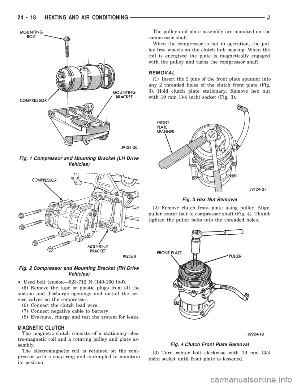
²Used belt tensionÐ623-712 N (140-160 lb-f).
(5) Remove the tape or plastic plugs from all the
suction and discharge openings and install the ser-
vice valves on the compressor.
(6) Connect the clutch lead wire.
(7) Connect negative cable to battery.
(8) Evacuate, charge and test the system for leaks.
MAGNETIC CLUTCH
The magnetic clutch consists of a stationary elec-
tro-magnetic coil and a rotating pulley and plate as-
sembly.
The electromagnetic coil is retained on the com-
pressor with a snap ring and is dimpled to maintain
its position.The pulley and plate assembly are mounted on the
compressor shaft.
When the compressor is not in operation, the pul-
ley free wheels on the clutch hub bearing. When the
coil is energized the plate is magnetically engaged
with the pulley and turns the compressor shaft.
REMOVAL
(1) Insert the 2 pins of the front plate spanner into
any 2 threaded holes of the clutch front plate (Fig.
3). Hold clutch plate stationary. Remove hex nut
with 19 mm (3/4 inch) socket (Fig. 3).
(2) Remove clutch front plate using puller. Align
puller center bolt to compressor shaft (Fig. 4). Thumb
tighten the puller bolts into the threaded holes.
(3) Turn center bolt clockwise with 19 mm (3/4
inch) socket until front plate is loosened.
Fig. 1 Compressor and Mounting Bracket (LH Drive
Vehicles)
Fig. 2 Compressor and Mounting Bracket (RH Drive
Vehicles)
Fig. 3 Hex Nut Removal
Fig. 4 Clutch Front Plate Removal
24 - 18 HEATING AND AIR CONDITIONINGJ
Page 1682 of 1784
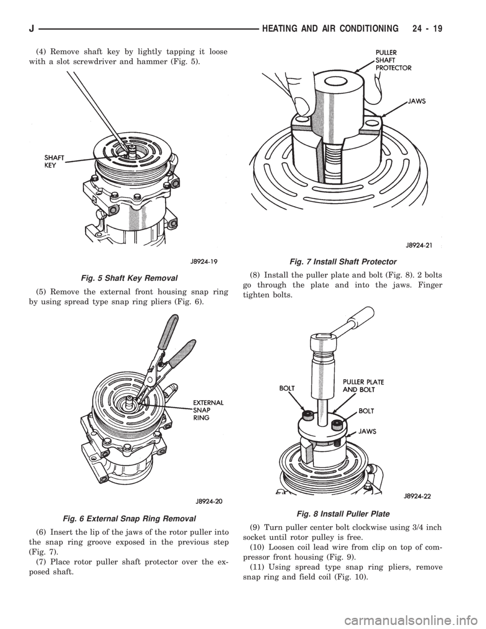
(4) Remove shaft key by lightly tapping it loose
with a slot screwdriver and hammer (Fig. 5).
(5) Remove the external front housing snap ring
by using spread type snap ring pliers (Fig. 6).
(6) Insert the lip of the jaws of the rotor puller into
the snap ring groove exposed in the previous step
(Fig. 7).
(7) Place rotor puller shaft protector over the ex-
posed shaft.(8) Install the puller plate and bolt (Fig. 8). 2 bolts
go through the plate and into the jaws. Finger
tighten bolts.
(9) Turn puller center bolt clockwise using 3/4 inch
socket until rotor pulley is free.
(10) Loosen coil lead wire from clip on top of com-
pressor front housing (Fig. 9).
(11) Using spread type snap ring pliers, remove
snap ring and field coil (Fig. 10).
Fig. 5 Shaft Key Removal
Fig. 6 External Snap Ring Removal
Fig. 7 Install Shaft Protector
Fig. 8 Install Puller Plate
JHEATING AND AIR CONDITIONING 24 - 19
Page 1683 of 1784
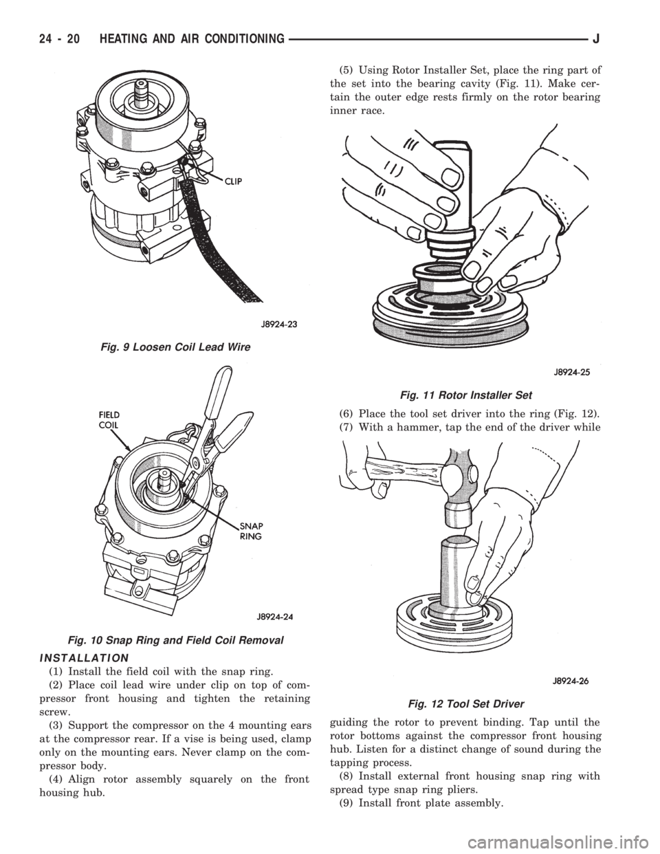
INSTALLATION
(1) Install the field coil with the snap ring.
(2) Place coil lead wire under clip on top of com-
pressor front housing and tighten the retaining
screw.
(3) Support the compressor on the 4 mounting ears
at the compressor rear. If a vise is being used, clamp
only on the mounting ears. Never clamp on the com-
pressor body.
(4) Align rotor assembly squarely on the front
housing hub.(5) Using Rotor Installer Set, place the ring part of
the set into the bearing cavity (Fig. 11). Make cer-
tain the outer edge rests firmly on the rotor bearing
inner race.
(6) Place the tool set driver into the ring (Fig. 12).
(7) With a hammer, tap the end of the driver while
guiding the rotor to prevent binding. Tap until the
rotor bottoms against the compressor front housing
hub. Listen for a distinct change of sound during the
tapping process.
(8) Install external front housing snap ring with
spread type snap ring pliers.
(9) Install front plate assembly.
Fig. 9 Loosen Coil Lead Wire
Fig. 10 Snap Ring and Field Coil Removal
Fig. 11 Rotor Installer Set
Fig. 12 Tool Set Driver
24 - 20 HEATING AND AIR CONDITIONINGJ
Page 1684 of 1784
²Check that original clutch shims are in place on
compressor shaft.
²Replace compressor shaft key.
²Align front plate keyway to compressor shaft key.
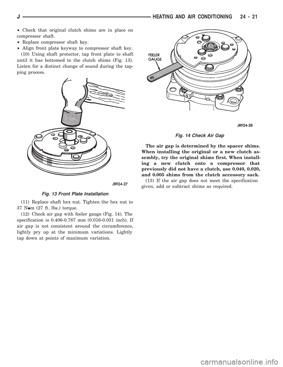
(10) Using shaft protector, tap front plate to shaft
until it has bottomed to the clutch shims (Fig. 13).
Listen for a distinct change of sound during the tap-
ping process.
(11) Replace shaft hex nut. Tighten the hex nut to
37 NIm (27 ft. lbs.) torque.
(12) Check air gap with feeler gauge (Fig. 14). The
specification is 0.406-0.787 mm (0.016-0.031 inch). If
air gap is not consistent around the circumference,
lightly pry up at the minimum variations. Lightly
tap down at points of maximum variation.The air gap is determined by the spacer shims.
When installing the original or a new clutch as-
sembly, try the original shims first. When install-
ing a new clutch onto a compressor that
previously did not have a clutch, use 0.040, 0.020,
and 0.005 shims from the clutch accessory sack.
(13) If the air gap does not meet the specification
given, add or subtract shims as required.
Fig. 13 Front Plate Installation
Fig. 14 Check Air Gap
JHEATING AND AIR CONDITIONING 24 - 21