Page 1669 of 1784

(18) Disconnect the charging hoses from the ser-
vice valves.
COMPRESSOR OIL LEVEL
The compressor oil level must be checked and ad-
justed if the system has been discharged rapidly, or
when a component has been replaced. If a replace-
ment compressor is being installed, it must be filled
with new compressor oil (Suniso 5GS, or equivalent).
The normal quantity of oil required for the com-
pressor and entire system is 136 ml (4.6 fluid oz.) for
SD 709 compressor. DO NOT overfill the compressor.
Excessive amounts of oil in the system will hinder
compressor operation and reduce A/C performance.
CAUTION: The compressor is a high speed unit.
Satisfactory operation is dependent on sufficient lu-
brication; however, excess oil will hinder A/C per-
formance.
Two oil level checking procedures are necessary.
Use Procedure (A) when the compressor is being re-
placed and the system was discharged properly (no
oil loss). Use Procedure (B) for routine maintenance
or when checking oil level after replacing a system
component.
In cases where rapid loss of refrigerant and oil
occurred, the system must be evacuated and
purged. Then the compressor must be filled with
the necessary amount of oil to fill the entire sys-
tem.
PROCEDURE A
(1) Remove the oil filler plug, discharge cap and
suction port caps from the original and replacement
compressor.
(2) Use a clean container to drain the oil from the
replacement compressor. Drain the oil through the
oil filler plug hole, the discharge and suction. Then
rotate clutch front plate several times to push the oil
on cylinder out to discharge chamber of cylinder
head and drain the oil from discharge port.
(3) Drain the oil from the original compressor into
a measuring cup or graduated beaker in the same
way as Step 2. Note the amount of oil drained.
(4) Fill the replacement compressor with the same
amount of oil drained from the original compressor
plus 30 ml (1 fluid oz.).
FOR EXAMPLE:ÐIf the old compressor contained
103.5 ml (3.5 fluid oz.) of oil, fill the replacement
compressor with a total of 133 ml (4.5 fluid oz.) of oil.
PROCEDURE B
(1) Start the engine and operate the engine at idle.
(2) Operate the air conditioning system for 10 min-
utes to return the maximum amount of oil in the sys-
tem to the compressor.(3) Stop the engine and disconnect the magnetic
clutch feed wire.
(4) Front-seat the discharge and suction service
valves.
(5) Determine the mounting angle.
(a) Position an Angle Gauge across the flat sur-
faces of the front mounting ears.
(b) Center the bubble.
(c) Read the mounting angle to the closest de-
gree.
(d) These vehicles should have 0É mounting an-
gle.
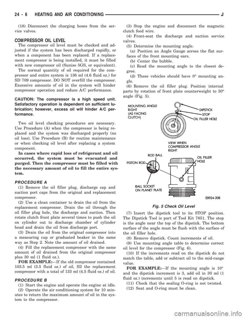
(6) Remove the oil filler plug. Position internal
parts by rotation of front plate counterweight to 30É
angle (Fig. 5).
(7) Insert the dipstick tool to its STOP position.
The Dipstick Tool is part of Tool Kit 7851. The stop
is the angle near the top of the dipstick. The bottom
surface of the angle must be flush with the surface of
the oil filler hole.
(8) Remove dipstick. Count increments of oil.
(9) Use mounting angle table to determine correct
oil level for the compressor (Fig. 6).
(10) If the increments read on the dipstick do not
match the table, add or subtract oil to the mid-range
value.
FOR EXAMPLE:ÐIf the mounting angle is 10É
and the dipstick increment is 3, add oil in 30 ml (1
fluid oz.) increments until 5 is read on dipstick.
(11) Check that the sealing O-ring is not twisted.
(12) Seat and O-ring must be clean.
Fig. 5 Check Oil Level
24 - 6 HEATING AND AIR CONDITIONINGJ
Page 1670 of 1784
(13) Install the compressor oil filler plug. Tighten
the plug to 10 NIm (7 ft. lbs.) torque. DO NOT over-
tighten the plug to stop a leak.
Fig. 6 Mounting Angle/Oil Level Table
JHEATING AND AIR CONDITIONING 24 - 7
Page 1671 of 1784

SERVICE DIAGNOSISÐMECHANICAL
GENERAL
The reason for a decrease in cooling or heating ef-
ficiency must be understood before attempting repair
or replacement of parts. Determined if the condition
is the air conditioner, the heating system, its compo-
nents or the in the air flow system.
The air conditioning system generally operates at
peak efficiency at normal highway speeds. However,
a slight reduction in A/C performance may be expe-
rienced in congested city driving conditions; espe-
cially when ambient temperatures are high.
When diagnosing a gradual decrease in A/C perfor-
mance, remember to check condition of the condenser
and radiator fins. Air flow blockage of either compo-
nent, caused by dirt, foreign material or insects, will
affect the air conditioning and engine cooling sys-
tems. Vehicles equipped with a protective screen, can
restrict air flow to the radiator and condenser.
During high outside operating temperatures, a
slight increase in engine coolant temperature will oc-
cur when the air conditioner is operating.
A/C PERFORMANCE TEST
The pressure developed on the high side and low
side of the compressor indicates whether the system
is operating properly.
WARNING: USE EXTREME CAUTION WHEN THE
ENGINE IS OPERATING. DO NOT STAND IN A DI-
RECT LINE WITH THE FAN. DO NOT PUT YOUR
HANDS NEAR THE PULLEYS, BELTS OR FAN. DO
NOT WEAR LOOSE CLOTHING.
WARNING: WEAR SAFETY GOGGLES WHEN SER-
VICING THE REFRIGERATION SYSTEM
(1) Attach an engine tachometer and refrigerant
Pressure Gauge and Manifold Assembly Tool
C-4740-A.
(2) Close both hand valves on the gauge and man-
ifold assembly.
(3) Set both service hand valve stems to the mid-
position.
(4) Engine should be warmed up with doors, win-
dows and hood closed.
(5) Operate air conditioning system with the en-
gine running at 1,000 RPM. Set the controls for max-
imum A/C, temperature control on full cool and
blower switch on high.
(6) Insert a thermometer into center discharge air
outlet and observe the air temperature. The temper-
ature should be approximately 7ÉC (45ÉF) at 27ÉC
(80ÉF) ambient temperature after 5 minutes of oper-
ation.(7) Observe the high and low side pressures. The
evaporator suction pressure should be 207-241 kPag
(30-35 psig). The compressor discharge pressure
should be 1103-1633 kPag (160-235 psig). It should
be noted that high ambient temperature and humid-
ity conditions will cause higher pressures and tem-
perature conditions. If the clutch cycles, take
readings before clutch disengages.
(8) If pressures are abnormal, refer to the Pressure
and Performance Diagnosis Charts.
The following charts have been developed for quick
reference. If the step by step method used is not com-
pletely understood, refer to the correct section of the
Service Manual for more detailed information.
COMPRESSOR VALVE PLATEÐLEAK TESTS
This test can be preformed with the compressor in-
stalled in the vehicle.
Discharge or Suction Valve BreakageÐWhen
compressor is operating at idle speed, compressor
makes a ``clacking'' sound. Preform the Pressure Bal-
ancing Test.
Head Gasket BreakageÐAt idle speed, discharge
pressure does not increase to normal condition and
suction pressure is high. Preform the Pressure Bal-
ancing Test.
Pressure Balancing Test:
(1) Connect manifold gauge set to suction and dis-
charge ports.
(2) Run compressor for 5 minutes at idle speed and
stop.
(3) Measure elapsed time that discharge pressure
is balanced to suction pressure. If less than 2 min-
utes, it is determined that discharge valve or head
gasket is broken.
REFRIGERANT LEAK TEST
External leaks in the system can be located using
an electronic detector.
The electronic leak detector is recommended be-
cause it is light, accurate and most important, does
not expose the user to toxic gas fumes. An electronic
leak detector will locate R-12 leaks as small as 15 ml
(0.5 fluid oz.) per year.
WARNING: DO NOT USE A HALIDE TORCH. THE
HALIDE TORCH REQUIRES AN OPEN FLAME FOR
LEAK DETECTION. WHEN R-12 IS EXPOSED TO AN
OPEN FLAME, IT TURNS INTO PHOSGENE GAS
WHICH IS POISONOUS.
(1) Calibrate the detector as outlined in the manu-
facturer's instructions.
(2) Remove the flexible detector probe from the
case.
(3) Turn the detector control switch ON.
24 - 8 HEATING AND AIR CONDITIONINGJ
Page 1672 of 1784
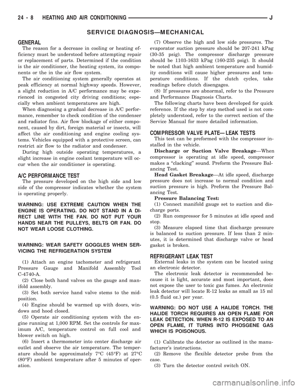
PRESSURE DIAGNOSIS
JHEATING AND AIR CONDITIONING 24 - 9
Page 1673 of 1784
PERFORMANCE DIAGNOSIS
24 - 10 HEATING AND AIR CONDITIONINGJ
Page 1674 of 1784
(4) Prepare the detector for use.
²Place the flexible probe tip near the leak port on
the detector.
²Adjust the BAT thumb-wheel a few teeth at a
time, until the light illuminates-then goes out when
the tip is removed from the leak port.
(5) Begin leak testing. Move the flexible probe
slowly under all suspect connections, joints and seals.Because R-12 refrigerant is heavier than air, leaks
are more readily detected on the lower side of com-
ponents being checked. The leak indicator light will
illuminate when a leak is detected. The indicator
light will go out if the probe tip is held near the leak
point for an extended period.
(6) Repair leaks as required.
(7) Evacuate and charge the system after leaks are
corrected.
HEATING SYSTEM DIAGNOSIS
JHEATING AND AIR CONDITIONING 24 - 11
Page 1675 of 1784
AIR CONDITIONING SYSTEM DIAGNOSIS
24 - 12 HEATING AND AIR CONDITIONINGJ
Page 1676 of 1784
COMPRESSOR DIAGNOSIS
JHEATING AND AIR CONDITIONING 24 - 13