1994 JEEP CHEROKEE heating
[x] Cancel search: heatingPage 1181 of 1784
(8) Check fluid condition. Fluid should be dark to
light red in color and free of dirt or debris.
(9) If fluid is discolored or smells burned but trans-
mission operation was OK, check cooler flow, flush
cooler and lines and change fluid and filter. Then
road test again to confirm proper operation.
(10) If fluid is black or dark brown, burned/turned
to sludge, contains large quantities of metal or fric-
tion material particles, transmission will need over-
haul. Especially if problems were evident during
road test and preliminary diagnosis. Fluid cooler
should also be flow tested and flushed if necessary.
EFFECTS OF INCORRECT FLUID LEVEL
A low fluid level allows the pump to take in air
along with the fluid. Air in the fluid will cause fluid
pressures to be low and develop slower than normal.
If the transmission is overfilled, the gears churn
the fluid into foam. This aerates the fluid causing
the same conditions that occur with a low level.
In either case, air bubbles cause fluid overheating,
oxidation and varnish buildup which interferes with
valve, clutch and servo operation. Foaming also
causes fluid expansion which can result in fluid over-
flow from the transmission vent or fill tube. Fluid
overflow can easily be mistaken for a leak if inspec-
tion is not careful.
TRANSMISSION THROTTLE VALVE CABLE
ADJUSTMENT
Throttle cable adjustment is important to proper
operation. This adjustment positions the throttle
valve which controls shift speed, quality and part
throttle downshift sensitivity.
If cable adjustment setting is too short, early shifts
and slippage between shifts may occur. If the setting
is too long, shifts may be delayed and part throttle
downshifts may be very sensitive. Refer to the In-Ve-
hicle Service section for adjustment procedure.
GEARSHIFT LINKAGE
Gearshift linkage adjustment is important because
it positions the valve body manual valve. Incorrect
adjustment will cause creeping in Neutral, prema-
ture clutch wear, delayed engagement in any gear, or
a no-start in Park or Neutral position.
Proper operation of the neutral start switch will
provide a quick check of linkage adjustment. Refer to
the In-Vehicle Service section for adjustment proce-
dure.
ROAD TEST
Before road testing, be sure the fluid level and all
linkage adjustments have been checked and adjusted
if necessary.
Observe engine performance during the road test.
A poorly tuned engine will not allow an accurate
analysis of transmission operation.Operate the transmission in all gear ranges. Check
for slippage and shift variations. Note whether the
shifts are harsh, spongy, delayed, early, or if part
throttle downshifts are sensitive.
Watch closely for slippage or engine flare which
usually indicates clutch, band or overrunning clutch
problems. If the condition is advanced, an overhaul
may be necessary to restore normal operation.
A slipping clutch or band can often be determined
by comparing which internal units are applied in the
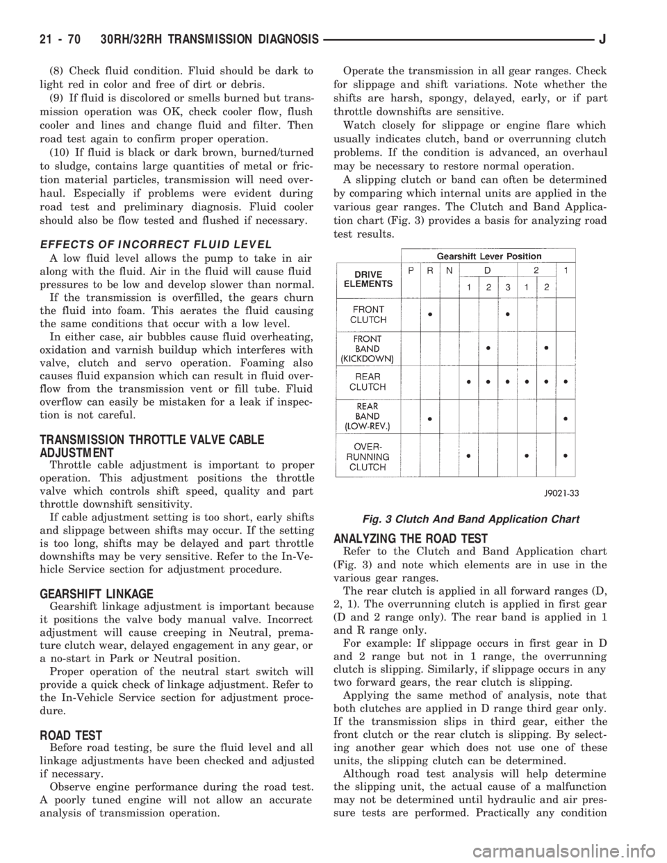
various gear ranges. The Clutch and Band Applica-
tion chart (Fig. 3) provides a basis for analyzing road
test results.
ANALYZING THE ROAD TEST
Refer to the Clutch and Band Application chart
(Fig. 3) and note which elements are in use in the
various gear ranges.
The rear clutch is applied in all forward ranges (D,
2, 1). The overrunning clutch is applied in first gear
(D and 2 range only). The rear band is applied in 1
and R range only.
For example: If slippage occurs in first gear in D
and 2 range but not in 1 range, the overrunning
clutch is slipping. Similarly, if slippage occurs in any
two forward gears, the rear clutch is slipping.
Applying the same method of analysis, note that
both clutches are applied in D range third gear only.
If the transmission slips in third gear, either the
front clutch or the rear clutch is slipping. By select-
ing another gear which does not use one of these
units, the slipping clutch can be determined.
Although road test analysis will help determine
the slipping unit, the actual cause of a malfunction
may not be determined until hydraulic and air pres-
sure tests are performed. Practically any condition
Fig. 3 Clutch And Band Application Chart
21 - 70 30RH/32RH TRANSMISSION DIAGNOSISJ
Page 1449 of 1784
WHEELS
GENERAL INFORMATION
Original equipment wheels are designed for the
specified Maximum Vehicle Capacity.
All models use steel or cast aluminum drop center
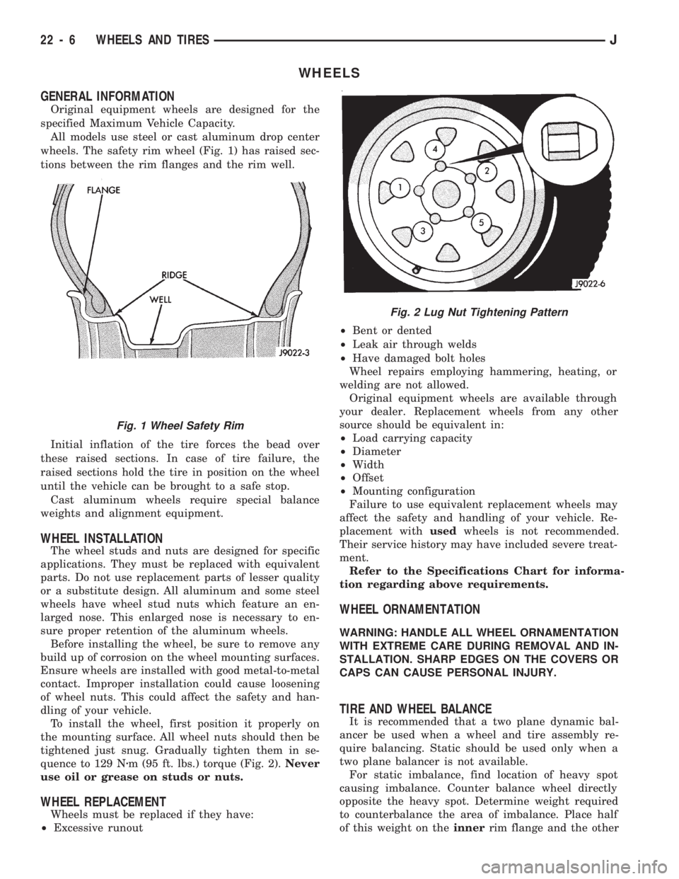
wheels. The safety rim wheel (Fig. 1) has raised sec-
tions between the rim flanges and the rim well.
Initial inflation of the tire forces the bead over
these raised sections. In case of tire failure, the
raised sections hold the tire in position on the wheel
until the vehicle can be brought to a safe stop.
Cast aluminum wheels require special balance
weights and alignment equipment.
WHEEL INSTALLATION
The wheel studs and nuts are designed for specific
applications. They must be replaced with equivalent
parts. Do not use replacement parts of lesser quality
or a substitute design. All aluminum and some steel
wheels have wheel stud nuts which feature an en-
larged nose. This enlarged nose is necessary to en-
sure proper retention of the aluminum wheels.
Before installing the wheel, be sure to remove any
build up of corrosion on the wheel mounting surfaces.
Ensure wheels are installed with good metal-to-metal
contact. Improper installation could cause loosening
of wheel nuts. This could affect the safety and han-
dling of your vehicle.
To install the wheel, first position it properly on
the mounting surface. All wheel nuts should then be
tightened just snug. Gradually tighten them in se-
quence to 129 Nzm (95 ft. lbs.) torque (Fig. 2).Never
use oil or grease on studs or nuts.
WHEEL REPLACEMENT
Wheels must be replaced if they have:
²Excessive runout²Bent or dented
²Leak air through welds
²Have damaged bolt holes
Wheel repairs employing hammering, heating, or
welding are not allowed.
Original equipment wheels are available through
your dealer. Replacement wheels from any other
source should be equivalent in:
²Load carrying capacity
²Diameter
²Width
²Offset
²Mounting configuration
Failure to use equivalent replacement wheels may
affect the safety and handling of your vehicle. Re-
placement withusedwheels is not recommended.
Their service history may have included severe treat-
ment.
Refer to the Specifications Chart for informa-
tion regarding above requirements.
WHEEL ORNAMENTATION
WARNING: HANDLE ALL WHEEL ORNAMENTATION
WITH EXTREME CARE DURING REMOVAL AND IN-
STALLATION. SHARP EDGES ON THE COVERS OR
CAPS CAN CAUSE PERSONAL INJURY.
TIRE AND WHEEL BALANCE
It is recommended that a two plane dynamic bal-
ancer be used when a wheel and tire assembly re-
quire balancing. Static should be used only when a
two plane balancer is not available.
For static imbalance, find location of heavy spot
causing imbalance. Counter balance wheel directly
opposite the heavy spot. Determine weight required
to counterbalance the area of imbalance. Place half
of this weight on theinnerrim flange and the other
Fig. 2 Lug Nut Tightening Pattern
Fig. 1 Wheel Safety Rim
22 - 6 WHEELS AND TIRESJ
Page 1591 of 1784
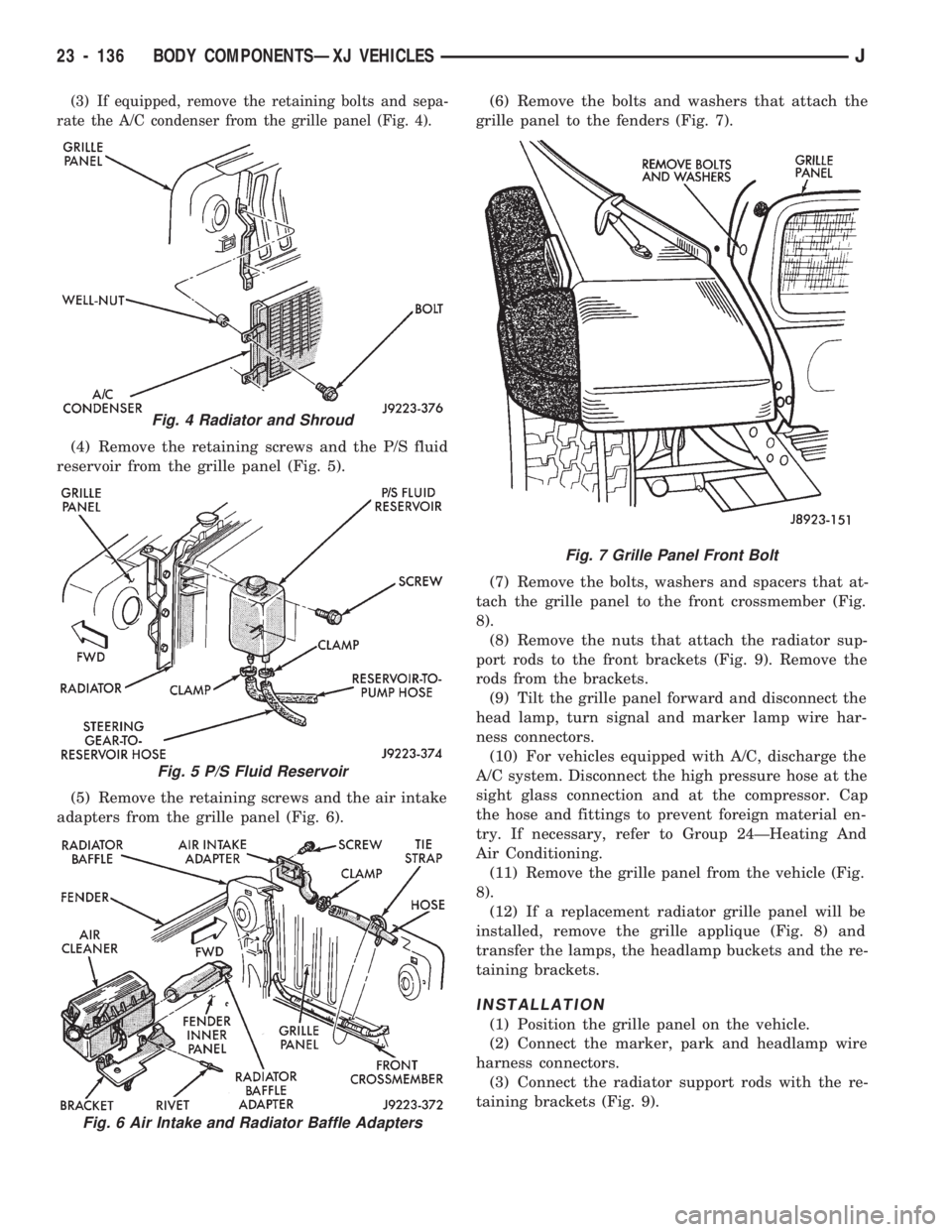
(3) If equipped, remove the retaining bolts and sepa-
rate the A/C condenser from the grille panel (Fig. 4).
(4) Remove the retaining screws and the P/S fluid
reservoir from the grille panel (Fig. 5).
(5) Remove the retaining screws and the air intake
adapters from the grille panel (Fig. 6).(6) Remove the bolts and washers that attach the
grille panel to the fenders (Fig. 7).
(7) Remove the bolts, washers and spacers that at-
tach the grille panel to the front crossmember (Fig.
8).
(8) Remove the nuts that attach the radiator sup-
port rods to the front brackets (Fig. 9). Remove the
rods from the brackets.
(9) Tilt the grille panel forward and disconnect the
head lamp, turn signal and marker lamp wire har-
ness connectors.
(10) For vehicles equipped with A/C, discharge the
A/C system. Disconnect the high pressure hose at the
sight glass connection and at the compressor. Cap
the hose and fittings to prevent foreign material en-
try. If necessary, refer to Group 24ÐHeating And
Air Conditioning.
(11) Remove the grille panel from the vehicle (Fig.
8).
(12) If a replacement radiator grille panel will be
installed, remove the grille applique (Fig. 8) and
transfer the lamps, the headlamp buckets and the re-
taining brackets.
INSTALLATION
(1) Position the grille panel on the vehicle.
(2) Connect the marker, park and headlamp wire
harness connectors.
(3) Connect the radiator support rods with the re-
taining brackets (Fig. 9).
Fig. 4 Radiator and Shroud
Fig. 5 P/S Fluid Reservoir
Fig. 6 Air Intake and Radiator Baffle Adapters
Fig. 7 Grille Panel Front Bolt
23 - 136 BODY COMPONENTSÐXJ VEHICLESJ
Page 1664 of 1784
HEATING AND AIR CONDITIONING
CONTENTS
page page
CLIMATE CONTROL SYSTEMÐXJ VEHICLES . 22
CLIMATE CONTROL SYSTEMÐYJ VEHICLES . 37
COMPRESSOR OVERHAUL............... 17
GENERAL INFORMATION.................. 1SERVICE DIAGNOSISÐELECTRICAL........ 14
SERVICE DIAGNOSISÐMECHANICAL........ 8
TORQUE SPECIFICATIONS................ 45
GENERAL INFORMATION
INDEX
page page
A/C Operation............................ 1
Compressor Oil Level...................... 6
Pressure Gauge and Manifold Assembly........ 2
Refrigerant (R-12)......................... 1
Service Precautions........................ 2Service Valves........................... 3
System Charge........................... 5
System Discharge......................... 4
System Evacuation........................ 4
A/C OPERATION
The compressor increases the pressure and temper-
ature of the refrigerant. The heated refrigerant vapor
is then pumped into the condenser where it cools by
the air passing over the condenser fins. As the refrig-
erant cools in the condenser, it condenses into a liq-
uid. Still under high pressure, the liquid refrigerant
passes into the receiver. The receiver acts as a reser-
voir to furnish refrigerant to the expansion (H) valve
at all times. From the receiver, the high pressure liq-
uid refrigerant passes to the expansion (H) valve.
The expansion (H) valve meters refrigerant into the
evaporator where a low pressure is maintained by
the suction side of the compressor. As it enters the
evaporator, the refrigerant immediately begins to
boil by absorbing heat from the air passing over the
evaporator core. Having given up its heat to boil the
refrigerant, the air is cooled and passes into the pas-
senger compartment of the vehicle. From the evapo-
rator the vaporized refrigerant is drawn back to the
compressor to repeat the cycle.
REFRIGERANT (R-12)
It is illegal to release R-12 into the atmosphere.
SAFETY PRECAUTIONS
WARNING: EXTREME CARE MUST BE TAKEN TO
PREVENT ANY LIQUID REFRIGERANT FROM COM-
ING IN CONTACT WITH THE SKIN AND ESPE-
CIALLY THE EYES. ALWAYS WEAR SAFETYGOGGLES WHEN SERVICING ANY PART OF THE
REFRIGERANT SYSTEM. IF EYE CONTACT IS
MADE, APPLY A FEW DROPS OF MINERAL OIL TO
THE EYES AND FLUSH WITH WATER FOR SEV-
ERAL MINUTES. SEEK MEDICAL ATTENTION IMME-
DIATELY.
The refrigerant used in the air conditioner system
is Refrigerant-12 (R-12). R-12 is nonexplosive, non-
flammable, non-corrosive, has practically no odor and
is heavier than air. Although it is classified as a safe
refrigerant, certain precautions must be observed to
protect the parts involved and the person who is
working on the unit. Liquid R-12, at normal atmo-
sphere pressures and temperatures, evaporates so
quickly that it has the tendency to freeze anything it
contacts.
WARNING: TO AVOID A DANGEROUS EXPLOSION,
NEVER WELD OR STEAM CLEAN NEAR AIR CON-
DITIONING LINES OR COMPONENTS. DO NOT
HEAT R-12 ABOVE 52ÉC (125ÉF).
The R-12 in the system is always under pressure.
Because the system is tightly sealed, heat applied to
any part could cause this pressure to build up exces-
sively.
JHEATING AND AIR CONDITIONING 24 - 1
Page 1665 of 1784
WARNING: LARGE AMOUNTS OF REFRIGERANT
RELEASED IN A CLOSED WORK AREA WILL DIS-
PLACE THE OXYGEN AND CAUSE SUFFOCATION.
ALWAYS MAINTAIN GOOD VENTILATION SUR-
ROUNDING THE WORK AREA.
R-12 gas, under normal conditions, is non-poison-
ous.
WARNING: THE DISCHARGE OF R-12 GAS NEAR
AN OPEN FLAME CAN PRODUCE A VERY POISON-
OUS GAS CALLED PHOSGENE. PHOSGENE IS
GENERATED WHEN A FLAME-TYPE LEAK DETEC-
TOR IS USED.
CAUTION: When charging an A/C system always
keep the tank in an upright position. If the tank is
on its side or upside down, liquid refrigerant will
enter the system and may damage the compressor.
In most instances when charging or adding refrig-
erant, moderate heat is required to bring the pres-
sure of the refrigerant above the pressure of the
system. A bucket or large pan of hot water, not over
52ÉC (125ÉF), is all the heat required for this pur-
pose. DO NOT heat the refrigerant container with a
blow torch or any other means that would raise the
temperature and pressure above this temperature.
CAUTION: DO NOT allow liquid refrigerant to touch
bright metal. Refrigerant will tarnish bright metal
and chrome surfaces. Refrigerant in combination
with moisture is very corrosive and can cause ex-
tensive damage to all metal surfaces.
Avoid splashing the refrigerant on any surface.
RECYCLING
(R-12) refrigerant is a chloroflorocarbon (CFC) that
can contribute to the depletion of the ozone layer in
the upper atmosphere. Ozone filters out harmful ra-
diation from the sun. To assist in protecting the
ozone layer, Chrysler Corporation requires that an
(R-12) refrigerant recovery device that meets SAE
standard J1991 be used. Contact an automotive ser-
vice equipment supplier for refrigerant recycling
equipment that is available in your area. Refer to
the operating instructions provided with the recy-
cling equipment for proper operation.
SERVICE PRECAUTIONS
Never open or loosen a connection before discharg-
ing the system refrigerant.
A system which has been opened to replace a com-
ponent or one which has discharged through leakage
must be evacuated before charging.
Immediately after disconnecting a component from
the system, seal the open fittings with a cap or plug.Before disconnecting a component from the system,
clean the outside of the fittings thoroughly.
DO NOT remove the sealing caps from a replace-
ment component until ready to install.
Refrigerant oil will absorb moisture from the atmo-
sphere if left uncapped. DO NOT open an oil con-
tainer until ready to use and install the cap
immediately after using. Store the oil only in a clean
moisture-free container.
Before connecting an open fitting always install a
new seal ring. Coat the fitting and seal with clean
refrigerant oil before connecting.
When installing a refrigerant line avoid sharp
bends. Position the line away from the exhaust or
any sharp edges which may chafe the line.
Tighten fittings only to the specified torque. The
copper and aluminum fittings used in the A/C system
will not tolerate over tightening.
When disconnecting a fitting use a wrench on both
halves of the fitting to prevent twisting of the refrig-
erant lines or tubes.
DO NOT open a refrigerant system or uncap a re-
placement component unless it is as close as possible
to room temperature. This will prevent condensation
from forming inside of a component which is cooler
than the surrounding air.
Keep service tools and the work area clean. Con-
tamination of A/C system through careless work hab-
its must be avoided.
PRESSURE GAUGE AND MANIFOLD ASSEMBLY
Pressure Gauge and Manifold Assembly Tool
C-3740-B (Fig. 1) is the most important tool used to
service the air conditioning system. The gauge as-
sembly is used to determine:
²System high side gauge pressures
²System low side gauge pressures
²The correct refrigerant charge
²System diagnosis
It is designed to provide simultaneous high and low
side pressure indications, because these pressures
must be compared to determine the correct system
operation.
LOW SIDE GAUGE
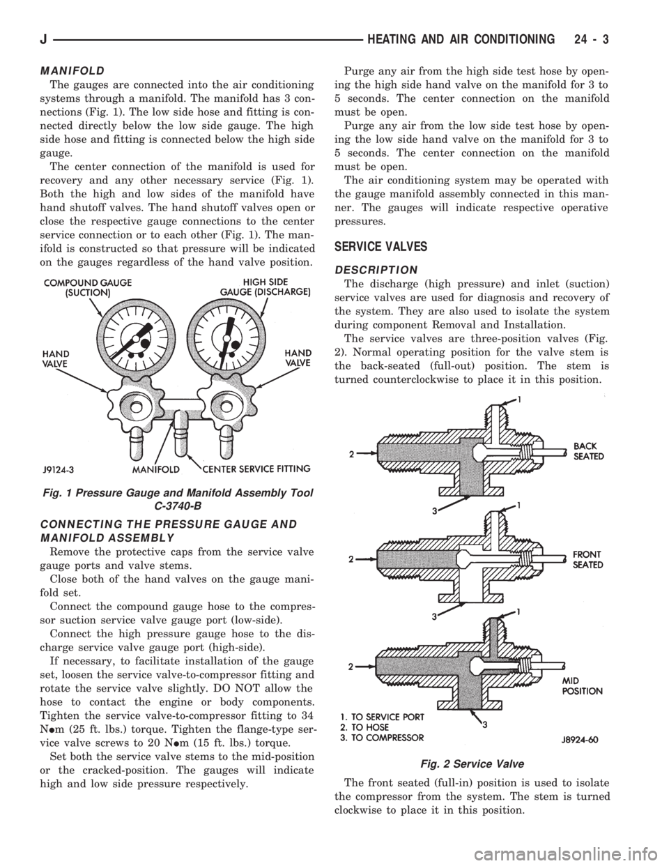
The low side gauge is a compound gauge, which
means that it will register both pressure and vacuum
(Fig. 1). The compound gauge is calibrated 0-1034
kPa (0-150 psi) pressure and 0-760 mm (0-30 in.) of
mercury vacuum. It is connected to the suction ser-
vice valve to check the low side pressure or vacuum.
HIGH SIDE GAUGE
The high side gauge is used to check the pressure
in the discharge side of the air conditioning system
(Fig. 1).
24 - 2 HEATING AND AIR CONDITIONINGJ
Page 1666 of 1784
MANIFOLD
The gauges are connected into the air conditioning
systems through a manifold. The manifold has 3 con-
nections (Fig. 1). The low side hose and fitting is con-
nected directly below the low side gauge. The high
side hose and fitting is connected below the high side
gauge.
The center connection of the manifold is used for
recovery and any other necessary service (Fig. 1).
Both the high and low sides of the manifold have
hand shutoff valves. The hand shutoff valves open or
close the respective gauge connections to the center
service connection or to each other (Fig. 1). The man-
ifold is constructed so that pressure will be indicated
on the gauges regardless of the hand valve position.
CONNECTING THE PRESSURE GAUGE AND
MANIFOLD ASSEMBLY
Remove the protective caps from the service valve
gauge ports and valve stems.
Close both of the hand valves on the gauge mani-
fold set.
Connect the compound gauge hose to the compres-
sor suction service valve gauge port (low-side).
Connect the high pressure gauge hose to the dis-
charge service valve gauge port (high-side).
If necessary, to facilitate installation of the gauge
set, loosen the service valve-to-compressor fitting and
rotate the service valve slightly. DO NOT allow the
hose to contact the engine or body components.
Tighten the service valve-to-compressor fitting to 34
NIm (25 ft. lbs.) torque. Tighten the flange-type ser-
vice valve screws to 20 NIm (15 ft. lbs.) torque.
Set both the service valve stems to the mid-position
or the cracked-position. The gauges will indicate
high and low side pressure respectively.Purge any air from the high side test hose by open-
ing the high side hand valve on the manifold for 3 to
5 seconds. The center connection on the manifold
must be open.
Purge any air from the low side test hose by open-
ing the low side hand valve on the manifold for 3 to
5 seconds. The center connection on the manifold
must be open.
The air conditioning system may be operated with
the gauge manifold assembly connected in this man-
ner. The gauges will indicate respective operative
pressures.
SERVICE VALVES
DESCRIPTION
The discharge (high pressure) and inlet (suction)
service valves are used for diagnosis and recovery of
the system. They are also used to isolate the system
during component Removal and Installation.
The service valves are three-position valves (Fig.
2). Normal operating position for the valve stem is
the back-seated (full-out) position. The stem is
turned counterclockwise to place it in this position.
The front seated (full-in) position is used to isolate
the compressor from the system. The stem is turned
clockwise to place it in this position.
Fig. 1 Pressure Gauge and Manifold Assembly Tool
C-3740-B
Fig. 2 Service Valve
JHEATING AND AIR CONDITIONING 24 - 3
Page 1667 of 1784
In the mid-position the gauge port is open. This po-
sition is used for pressure testing and for recovery of
the system.
DISCHARGE SERVICE VALVE ADAPTERS
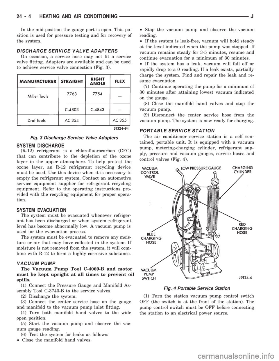
On occasion, a service hose may not fit a service
valve fitting. Adapters are available and can be used
to achieve service valve connection (Fig. 3).
SYSTEM DISCHARGE
(R-12) refrigerant is a chlorofluorocarbon (CFC)
that can contribute to the depletion of the ozone
layer in the upper atmosphere. To help protect the
ozone layer, an R-12 refrigerant recycling device
must be used. Use this device when it is necessary to
empty the refrigerant system. Contact an automotive
service equipment supplier for refrigerant recycling
equipment. Refer to the operating instructions pro-
vided with the recycling equipment for proper opera-
tion.
SYSTEM EVACUATION
The system must be evacuated whenever refriger-
ant has been discharged or when system refrigerant
level has become abnormally low. A vacuum pump is
used for the evacuation process.
The system must be evacuated to remove any mois-
ture or air that may have collected in the system. If
moisture is not removed from the system, it will com-
bine with R-12 to form a highly corrosive substance.
VACUUM PUMP
The Vacuum Pump Tool C-4069-B and motor
must be kept upright at all times to prevent oil
spills.
(1) Connect the Pressure Gauge and Manifold As-
sembly Tool C-3740-B to the service valves.
(2) Discharge the system.
(3) Connect the center service hose on the gauge
and manifold to the vacuum pump inlet fitting.
(4) Turn both manifold hand valves to the wide
open position.
(5) Start the vacuum pump and observe the vac-
uum gauge reading.
(6) Test the system for leaks as follows:
²Close the manifold hand valves.²Stop the vacuum pump and observe the vacuum
reading.
²If the system is leak-free, vacuum will hold steady
at the level indicated when the pump was stopped. If
vacuum remains steady for 3-5 minutes, resume and
continue evacuation for a minimum of 30 minutes.
²If the system has a leak, vacuum will fall off or
rapidly drop to a 0 reading. If a leak exists, partially
charge the system. Find and repair the leak and re-
sume evacuation.
(7) Continue operating the pump for a minimum of
30 minutes after attaining lowest vacuum indicated
on the gauge.
(8) Close the manifold hand valves and stop the
vacuum pump.
(9) Disconnect the center service hose from the
vacuum pump. The system is now ready for charging.
PORTABLE SERVICE STATION
The air conditioner service station is a self con-
tained, portable unit. It is equipped with a vacuum
pump, metering-charging cylinder, refrigerant sup-
ply, pressure and vacuum gauges, service hoses and
control valves (Fig. 4).
(1) Turn the station vacuum pump control switch
OFF (the switch is at the front of the station). The
pump control switch must be OFF before connecting
the station to an electrical power source.Fig. 3 Discharge Service Valve Adapters
Fig. 4 Portable Service Station
24 - 4 HEATING AND AIR CONDITIONINGJ
Page 1668 of 1784
(2) Close all the hand valves.
(3) Connect the red charging hose to the discharge
service valve.
(4) Connect the blue charging hose to the inlet
(suction) service valve.
(5) Discharge the system. Leave the suction and
discharge service valves in the mid-position.
CAUTION: The system must be completely dis-
charged into a recovery device before evacuating. If
the system is still charged, refrigerant can enter
and damage the vacuum pump.
(6) Connect the vacuum pump hose to the vacuum
pump inlet.
(7) Open the low and high pressure control valves
on the charging station.
(8) Start the vacuum pump. Open the vacuum con-
trol valve and note the vacuum reading.
(9) Test the system for leaks as follows:
²Close the manifold hand valves.
²Stop the vacuum pump and observe the vacuum
reading.
²If the system is leak-free, vacuum will hold steady
at the level indicated when the pump was stopped. If
vacuum remains steady for 3-5 minutes, resume and
continue evacuation for a minimum of 30 minutes.
²If the system has a leak, vacuum will fall off or
rapidly drop to a 0 reading. If a leak exists, partially
charge the system. Find and repair the leak and re-
sume evacuation.
(10) Continue evacuating the system for a mini-
mum of 30 minutes after attaining the lowest vac-
uum level.
(11) Fill the station charging cylinder while the
system is evacuating.
(12) Close the vacuum control valve and stop the
vacuum pump.
(13) Observe low pressure gauge to determine if a
system leak exists. If the system is leak-free, the sys-
tem is now ready for charging.
SYSTEM CHARGE
CHARGE CAPACITY
The recommended system charge is 1.1 kg (38 oz.)
of R-12 refrigerant for XJ vehicles and 0.9 kg (32 oz.)
for YJ vehicles.
Add an additional 28 grams (1 fluid oz.) of
compressor oil to the system when a hose, re-
ceiver-drier, condenser, expansion valve or
evaporator core is replaced.
PORTABLE SERVICE STATION
(1) Fill the station charging cylinder. Refrigerant
should be observed rising in the cylinder sight glass.
(2) Slightly open the valve at the top of the cylin-
der when pressure in the charging cylinder and re-frigerant supply tank are equal. This relieves head
pressure allowing refrigerant to continue filling the
cylinder.
(3) Observe the pressure gauge at the top of the
cylinder. Rotate the plastic cover on the cylinder un-
til the pressure heading column corresponds with the
gauge pressure in-line with the sight glass.
FOR EXAMPLE:ÐThe pressure gauge at the top
of the cylinder indicates 483 kPa (70 psi). Locate the
column with the pressure heading of 483 (70) and ro-
tate the cover so the 483 (70) column aligns with the
sight glass.
(4) When refrigerant reaches the correct level in
the sight glass, close the right hand valve at cylinder
base and on the refrigerant drum.
(5) Close the valve at the top of the charging cyl-
inder.
(6) Check for bubbles in the refrigerant using the
cylinder sight glass. If bubbles appear in the refrig-
erant, tilt the charging station rearward momen-
tarily.
(7) Connect the heating element cord to the power
pack receptacle and turn the heater switch ON.
(8) Allow the refrigerant to warm for about 10
minutes while the vacuum pump is operating.
WARNING: WEAR GOGGLES TO PROTECT THE
EYES.
(9) Discharge and evacuate the system.
(10) Close the low pressure valve on the charging
station.
(11) Fully open the left hand refrigerant control
valve at the base of the cylinder and the high pres-
sure valve on the charging station.
(12) Charge the system.
(13) Close the refrigerant control valve and the
high pressure valve on the charging station.
CAUTION: DO NOT permit the liquid level to drop
below 0 on the cylinder sight glass.
(14) Close the manifold gauges after completion of
the charging operation and check the high and low
side pressures.
(15) Check system operation.
CAUTION: DO NOT check system pressures until
the high and low pressure valves on the charging
station are closed. The low pressure gauge could
be damaged if the valves are open.
(16) Close all the valves on the charging station
and close the refrigerant drum valve when all the op-
erations are completed.
(17) Back-seat the service valves by turning them
fully counterclockwise. Install the quick seal caps on
the valves afterward.
JHEATING AND AIR CONDITIONING 24 - 5