1994 JEEP CHEROKEE brake fluid
[x] Cancel search: brake fluidPage 896 of 1784
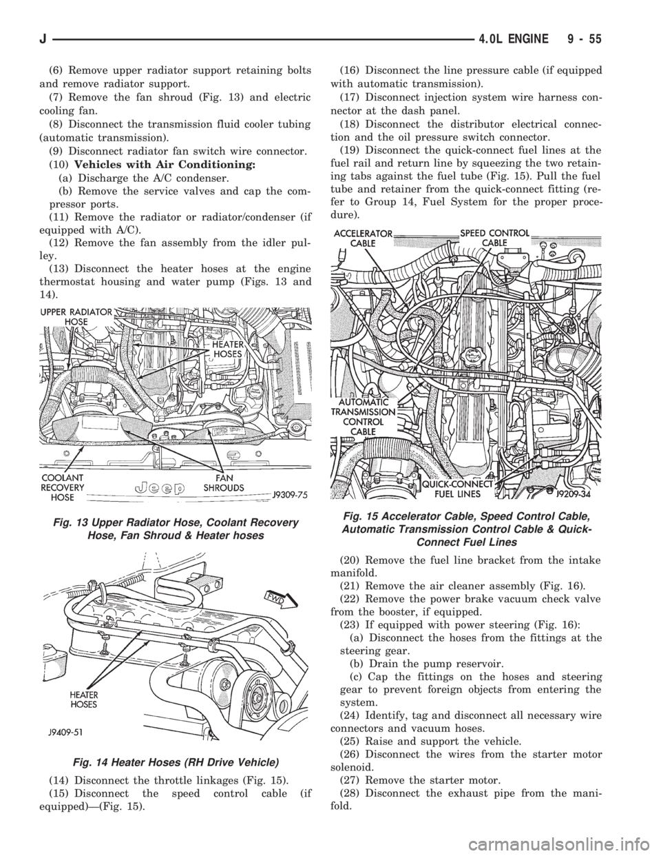
(6) Remove upper radiator support retaining bolts
and remove radiator support.
(7) Remove the fan shroud (Fig. 13) and electric
cooling fan.
(8) Disconnect the transmission fluid cooler tubing
(automatic transmission).
(9) Disconnect radiator fan switch wire connector.
(10)Vehicles with Air Conditioning:
(a) Discharge the A/C condenser.
(b) Remove the service valves and cap the com-
pressor ports.
(11) Remove the radiator or radiator/condenser (if
equipped with A/C).
(12) Remove the fan assembly from the idler pul-
ley.
(13) Disconnect the heater hoses at the engine
thermostat housing and water pump (Figs. 13 and
14).
(14) Disconnect the throttle linkages (Fig. 15).
(15) Disconnect the speed control cable (if
equipped)Ð(Fig. 15).(16) Disconnect the line pressure cable (if equipped
with automatic transmission).
(17) Disconnect injection system wire harness con-
nector at the dash panel.
(18) Disconnect the distributor electrical connec-
tion and the oil pressure switch connector.
(19) Disconnect the quick-connect fuel lines at the
fuel rail and return line by squeezing the two retain-
ing tabs against the fuel tube (Fig. 15). Pull the fuel
tube and retainer from the quick-connect fitting (re-
fer to Group 14, Fuel System for the proper proce-
dure).
(20) Remove the fuel line bracket from the intake
manifold.
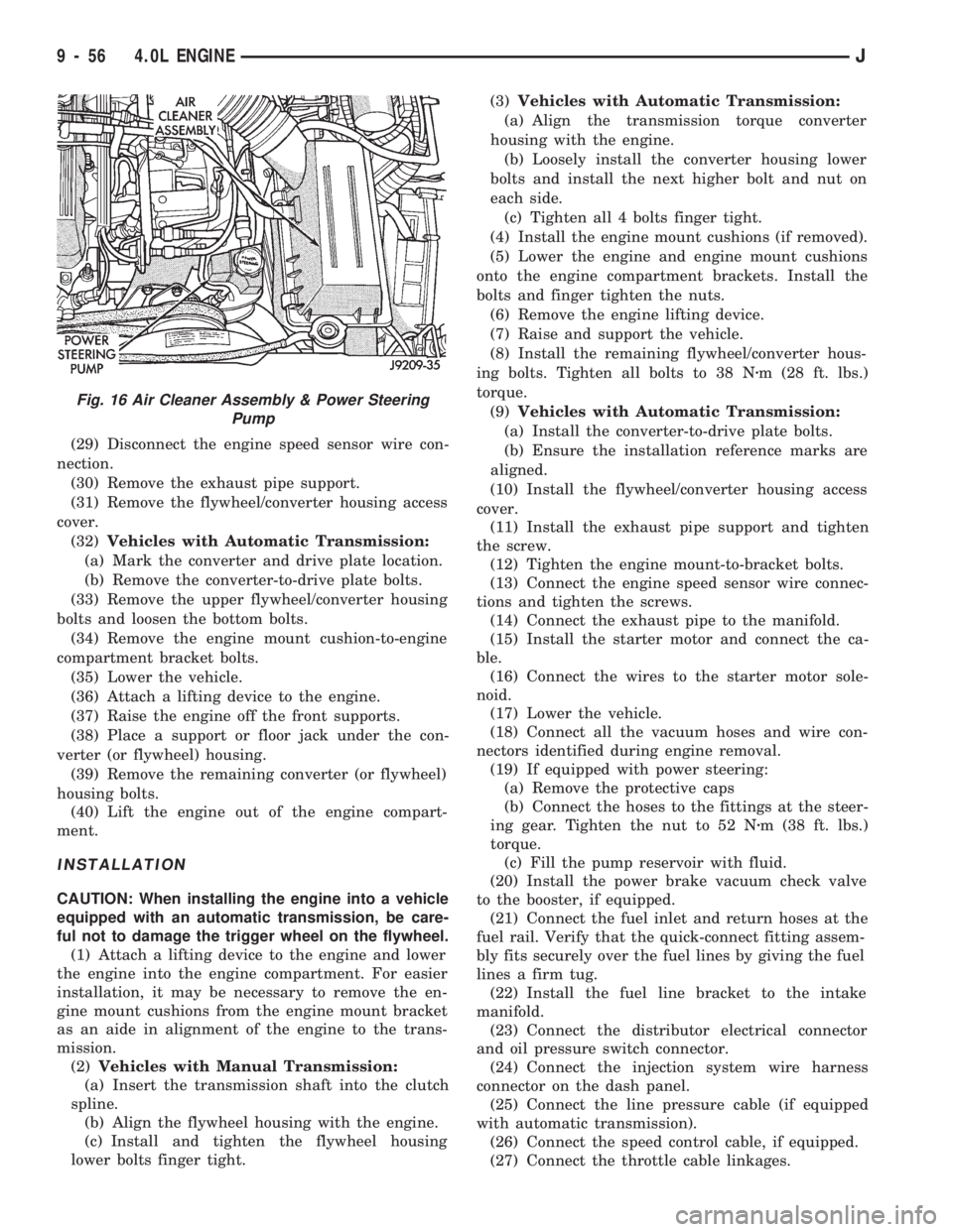
(21) Remove the air cleaner assembly (Fig. 16).
(22) Remove the power brake vacuum check valve
from the booster, if equipped.
(23) If equipped with power steering (Fig. 16):
(a) Disconnect the hoses from the fittings at the
steering gear.
(b) Drain the pump reservoir.
(c) Cap the fittings on the hoses and steering
gear to prevent foreign objects from entering the
system.
(24) Identify, tag and disconnect all necessary wire
connectors and vacuum hoses.
(25) Raise and support the vehicle.
(26) Disconnect the wires from the starter motor
solenoid.
(27) Remove the starter motor.
(28) Disconnect the exhaust pipe from the mani-
fold.
Fig. 13 Upper Radiator Hose, Coolant Recovery
Hose, Fan Shroud & Heater hoses
Fig. 14 Heater Hoses (RH Drive Vehicle)
Fig. 15 Accelerator Cable, Speed Control Cable,
Automatic Transmission Control Cable & Quick-
Connect Fuel Lines
J4.0L ENGINE 9 - 55
Page 897 of 1784
(29) Disconnect the engine speed sensor wire con-
nection.
(30) Remove the exhaust pipe support.
(31) Remove the flywheel/converter housing access
cover.
(32)Vehicles with Automatic Transmission:
(a) Mark the converter and drive plate location.
(b) Remove the converter-to-drive plate bolts.
(33) Remove the upper flywheel/converter housing
bolts and loosen the bottom bolts.
(34) Remove the engine mount cushion-to-engine
compartment bracket bolts.
(35) Lower the vehicle.
(36) Attach a lifting device to the engine.
(37) Raise the engine off the front supports.
(38) Place a support or floor jack under the con-
verter (or flywheel) housing.
(39) Remove the remaining converter (or flywheel)
housing bolts.
(40) Lift the engine out of the engine compart-
ment.
INSTALLATION
CAUTION: When installing the engine into a vehicle
equipped with an automatic transmission, be care-
ful not to damage the trigger wheel on the flywheel.
(1) Attach a lifting device to the engine and lower
the engine into the engine compartment. For easier
installation, it may be necessary to remove the en-
gine mount cushions from the engine mount bracket
as an aide in alignment of the engine to the trans-
mission.
(2)Vehicles with Manual Transmission:
(a) Insert the transmission shaft into the clutch
spline.
(b) Align the flywheel housing with the engine.
(c) Install and tighten the flywheel housing
lower bolts finger tight.(3)Vehicles with Automatic Transmission:
(a) Align the transmission torque converter
housing with the engine.
(b) Loosely install the converter housing lower
bolts and install the next higher bolt and nut on
each side.
(c) Tighten all 4 bolts finger tight.
(4) Install the engine mount cushions (if removed).
(5) Lower the engine and engine mount cushions
onto the engine compartment brackets. Install the
bolts and finger tighten the nuts.
(6) Remove the engine lifting device.
(7) Raise and support the vehicle.
(8) Install the remaining flywheel/converter hous-
ing bolts. Tighten all bolts to 38 Nzm (28 ft. lbs.)
torque.
(9)Vehicles with Automatic Transmission:
(a) Install the converter-to-drive plate bolts.
(b) Ensure the installation reference marks are
aligned.
(10) Install the flywheel/converter housing access
cover.
(11) Install the exhaust pipe support and tighten
the screw.
(12) Tighten the engine mount-to-bracket bolts.
(13) Connect the engine speed sensor wire connec-
tions and tighten the screws.
(14) Connect the exhaust pipe to the manifold.
(15) Install the starter motor and connect the ca-
ble.
(16) Connect the wires to the starter motor sole-
noid.
(17) Lower the vehicle.
(18) Connect all the vacuum hoses and wire con-
nectors identified during engine removal.
(19) If equipped with power steering:
(a) Remove the protective caps
(b) Connect the hoses to the fittings at the steer-
ing gear. Tighten the nut to 52 Nzm (38 ft. lbs.)
torque.
(c) Fill the pump reservoir with fluid.
(20) Install the power brake vacuum check valve
to the booster, if equipped.
(21) Connect the fuel inlet and return hoses at the
fuel rail. Verify that the quick-connect fitting assem-
bly fits securely over the fuel lines by giving the fuel
lines a firm tug.
(22) Install the fuel line bracket to the intake
manifold.
(23) Connect the distributor electrical connector
and oil pressure switch connector.
(24) Connect the injection system wire harness
connector on the dash panel.
(25) Connect the line pressure cable (if equipped
with automatic transmission).
(26) Connect the speed control cable, if equipped.
(27) Connect the throttle cable linkages.
Fig. 16 Air Cleaner Assembly & Power Steering
Pump
9 - 56 4.0L ENGINEJ
Page 900 of 1784
(17) Tighten the serpentine drive belt according to
the specifications listed in Group 7, Cooling System.
(18) Install the fan shroud and radiator (refer to
Group 7, Cooling System for the proper procedure).
(19) Connect the radiator hoses.
(20) Connect the throttle valve rod and retainer.
(21) Connect the throttle cable and install the rod.
(22) Install the throttle valve rod spring.
(23) Connect the speed control cable, if equipped.
(24) Connect the oxygen sensor wire connector.
(25) Install the vacuum hose and check valve on
the brake booster.
(26) Connect the coolant temperature sensor wire
connector.
(27) Connect the idle speed actuator wire connec-
tor.
(28) Connect the fuel inlet and return hoses at the
fuel rail. Verify that the quick-connect fitting assem-
bly fits securely over the fuel lines by giving the fuel
lines a firm tug.
(29) Install the fuel line bracket to the intake
manifold.
(30) Connect all fuel injection wire connections.
(31) Install the engine ground strap.
(32) Connect the ignition coil wire connector.
(33) Remove the coolant temperature sending unit
to permit air to escape from the block. Fill the cool-
ing system with coolant. Install the coolant tempera-
ture sending unit when the system is filled.
(34) If equipped with power steering:
(a) Remove the protective caps
(b) Connect the hoses to the fittings at the steer-
ing gear. Tighten the nut to 52 Nzm (38 ft. lbs.)
torque.
(c) Fill the pump reservoir with fluid.
(35) Install the battery and connect the battery ca-
bles.
(36) Install the air cleaner bonnet to the throttle
body.
(37) Install the air cleaner.
(38) Lower the hood and secure in place.
(39) Start the engine and inspect for leaks.
(40) Stop the engine and check the fluid levels.
Add fluid, as required.
ENGINE CYLINDER HEAD COVER
A cured gasket is part of the engine cylinder head
cover.
REMOVAL
(1) Disconnect negative cable from battery.
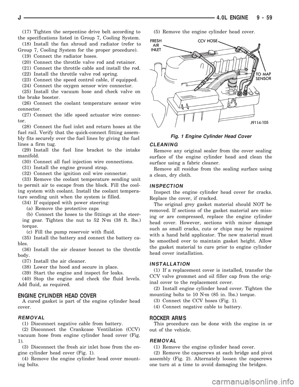
(2) Disconnect the Crankcase Ventilation (CCV)
vacuum hose from engine cylinder head cover (Fig.
1).
(3) Disconnect the fresh air inlet hose from the en-
gine cylinder head cover (Fig. 1).
(4) Remove the engine cylinder head cover mount-
ing bolts.(5) Remove the engine cylinder head cover.
CLEANING
Remove any original sealer from the cover sealing
surface of the engine cylinder head and clean the
surface using a fabric cleaner.
Remove all residue from the sealing surface using
a clean, dry cloth.
INSPECTION
Inspect the engine cylinder head cover for cracks.
Replace the cover, if cracked.
The original grey gasket material should NOT be
removed. If sections of the gasket material are miss-
ing or are compressed, replace the engine cylinder
head cover. However, sections with minor damage
such as small cracks, cuts or chips may be repaired
with a hand held applicator. The new material must
be smoothed over to maintain gasket height. Allow
the gasket material to cure prior to engine cylinder
head cover installation.
INSTALLATION
(1) If a replacement cover is installed, transfer the
CCV valve grommet and oil filler cap from the orig-
inal cover to the replacement cover.
(2) Install engine cylinder head cover. Tighten the
mounting bolts to 10 Nzm (85 in. lbs.) torque.
(3) Connect the CCV hoses (Fig. 1).
(4) Connect negative cable to battery.
ROCKER ARMS
This procedure can be done with the engine in or
out of the vehicle.
REMOVAL
(1) Remove the engine cylinder head cover.
(2) Remove the capscrews at each bridge and pivot
assembly (Fig. 2). Alternately loosen the capscrews
one turn at a time to avoid damaging the bridges.
Fig. 1 Engine Cylinder Head Cover
J4.0L ENGINE 9 - 59
Page 955 of 1784

YJ BUMPERS AND FRAME ATTACHED COMPONENTS
INDEX
page page
Generator Splash Shield................... 14
Body.................................. 18
Engine Front Support Cushion............... 15
Frame Crossmember Cover................. 14
Front Bumper........................... 14
Fuel and Brake Fluid Tube Retainer Clip....... 16
Fuel Filter Shield and Bracket............... 17
Fuel Tank Skid Plate...................... 16Muffler and Tailpipe Heat Shields............ 17
Muffler/Tailpipe Hanger Bracket.............. 16
Rear Bumper............................ 18
Rear Jounce Bumper..................... 18
Service Information....................... 14
Tow Hooks............................. 14
Transfer Case Skid Plate.................. 15
SERVICE INFORMATION
In some cases, components in the following proce-
dures either support, or are hidden by other compo-
nents.
FRONT BUMPER
The YJ front bumper is a one-piece rail (Fig. 1). A
front crossmember cover (Fig. 1) is also installed on
all YJ vehicles.
BUMPER REMOVAL
(1) Disconnect and remove the fog lamps, if
equipped.
(2) Remove the nuts and bolts that retain the
bumper extensions to the bumper rail and remove
the extensions.
(3) Remove the nuts and bolts that attach the
bumper rail/tow hooks to the frame rails.(4) Remove the bumper rail from the frame rails.
BUMPER INSTALLATION
(1) Position the front bumper on the frame rails.
(2) Install the bolts and attach the front bumper
rail (and tow hooks, if equipped) to the frame rails.
(3) Tighten the bolts to 102 Nzm (75 ft-lbs) torque.
(4) Position the bumper extensions on the bumper
rail and install the retaining bolts.
(5) Tighten the bolts to 104 Nzm (77 ft-lbs) torque.
(6) Install the fog lamps, if equipped.
FRAME CROSSMEMBER COVER
REMOVAL
(1) Remove the screws that attach the crossmem-
ber cover and support to the frame rails.
(2) Remove the crossmember cover and support
from the frame rails.
INSTALLATION
(1) Position the support and crossmember cover on
the frame rails.
(2) Install the attaching screws.
(3) Tighten the screws to 8 Nzm (72 in-lbs) torque.
TOW HOOKS
REMOVAL
(1) Remove the two bolts that attach the tow hook
to the bumper rail and to the frame rail.
(2) Remove the tow hook.
INSTALLATION
(1) Position the tow hook on the bumper rail and
frame rail.
(2) Install the attaching bolts.
(3) Tighten the bolts to 102 Nzm (75 ft-lbs) torque.
GENERATOR SPLASH SHIELD
REMOVAL
(1) Remove the shield retaining nut and washer
(Fig. 2) from the engine oil pan stud (2.5L engines
only).
Fig. 1 Front Bumper Rail, Crossmember Cover &
Tow Hooks
13 - 14 FRAME AND BUMPERSJ
Page 957 of 1784
FUEL TANK SKID PLATE
REMOVAL
(1) Position a support under the fuel tank skid
plate.
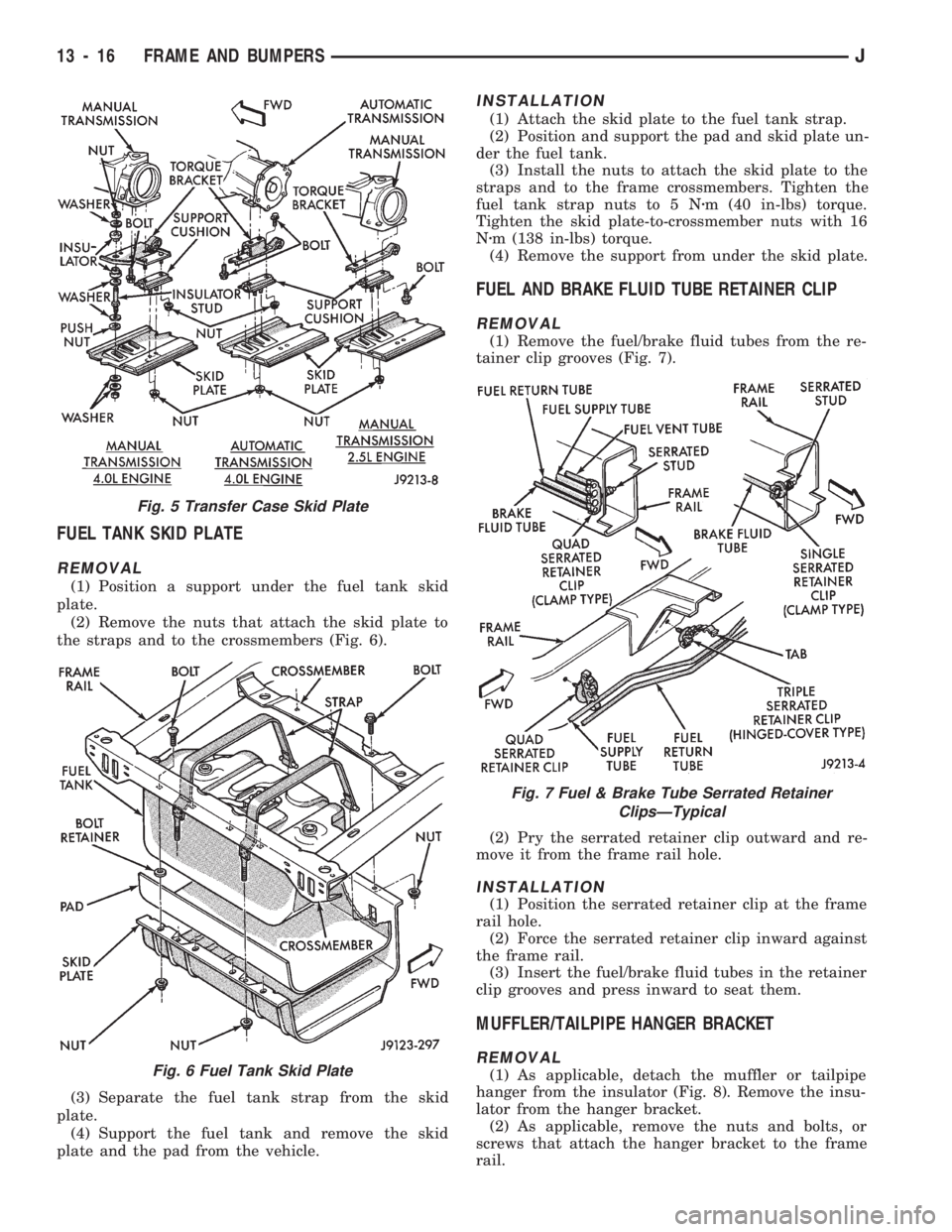
(2) Remove the nuts that attach the skid plate to
the straps and to the crossmembers (Fig. 6).
(3) Separate the fuel tank strap from the skid
plate.
(4) Support the fuel tank and remove the skid
plate and the pad from the vehicle.
INSTALLATION
(1) Attach the skid plate to the fuel tank strap.
(2) Position and support the pad and skid plate un-
der the fuel tank.
(3) Install the nuts to attach the skid plate to the
straps and to the frame crossmembers. Tighten the
fuel tank strap nuts to 5 Nzm (40 in-lbs) torque.
Tighten the skid plate-to-crossmember nuts with 16
Nzm (138 in-lbs) torque.
(4) Remove the support from under the skid plate.
FUEL AND BRAKE FLUID TUBE RETAINER CLIP
REMOVAL
(1) Remove the fuel/brake fluid tubes from the re-
tainer clip grooves (Fig. 7).
(2) Pry the serrated retainer clip outward and re-
move it from the frame rail hole.
INSTALLATION
(1) Position the serrated retainer clip at the frame
rail hole.
(2) Force the serrated retainer clip inward against
the frame rail.
(3) Insert the fuel/brake fluid tubes in the retainer
clip grooves and press inward to seat them.
MUFFLER/TAILPIPE HANGER BRACKET
REMOVAL
(1) As applicable, detach the muffler or tailpipe
hanger from the insulator (Fig. 8). Remove the insu-
lator from the hanger bracket.
(2) As applicable, remove the nuts and bolts, or
screws that attach the hanger bracket to the frame
rail.
Fig. 5 Transfer Case Skid Plate
Fig. 6 Fuel Tank Skid Plate
Fig. 7 Fuel & Brake Tube Serrated Retainer
ClipsÐTypical
13 - 16 FRAME AND BUMPERSJ
Page 979 of 1784
charges when the PCM supplies a ground. By switch-
ing the ground path on and off, the PCM regulates
ignition timing.
The sensors and switches that provide inputs to the
powertrain control module (PCM) comprise the En-
gine Control System. It is also comprised of the PCM
Outputs (engine control devices that the are operated
by the PCM).
SYSTEM DIAGNOSIS
The powertrain control module (PCM) tests many
of its own input and output circuits. If a Diagnostic
Trouble Code (DTC) is found in a major system, this
information is stored in the PCM memory. Refer to
On-Board Diagnostics in the MFI SystemÐGeneral
Diagnosis section of this group for DTC information.
POWERTRAIN CONTROL MODULE (PCM)
The PCM operates the fuel system. The PCM was
formerly referred to as the SBEC or engine control-
ler. The PCM is a pre-programmed, dual micropro-
cessor digital computer. It regulates ignition timing,
air-fuel ratio, emission control devices, charging sys-
tem, speed control, air conditioning compressor
clutch engagement and idle speed. The PCM can
adapt its programming to meet changing operating
conditions.
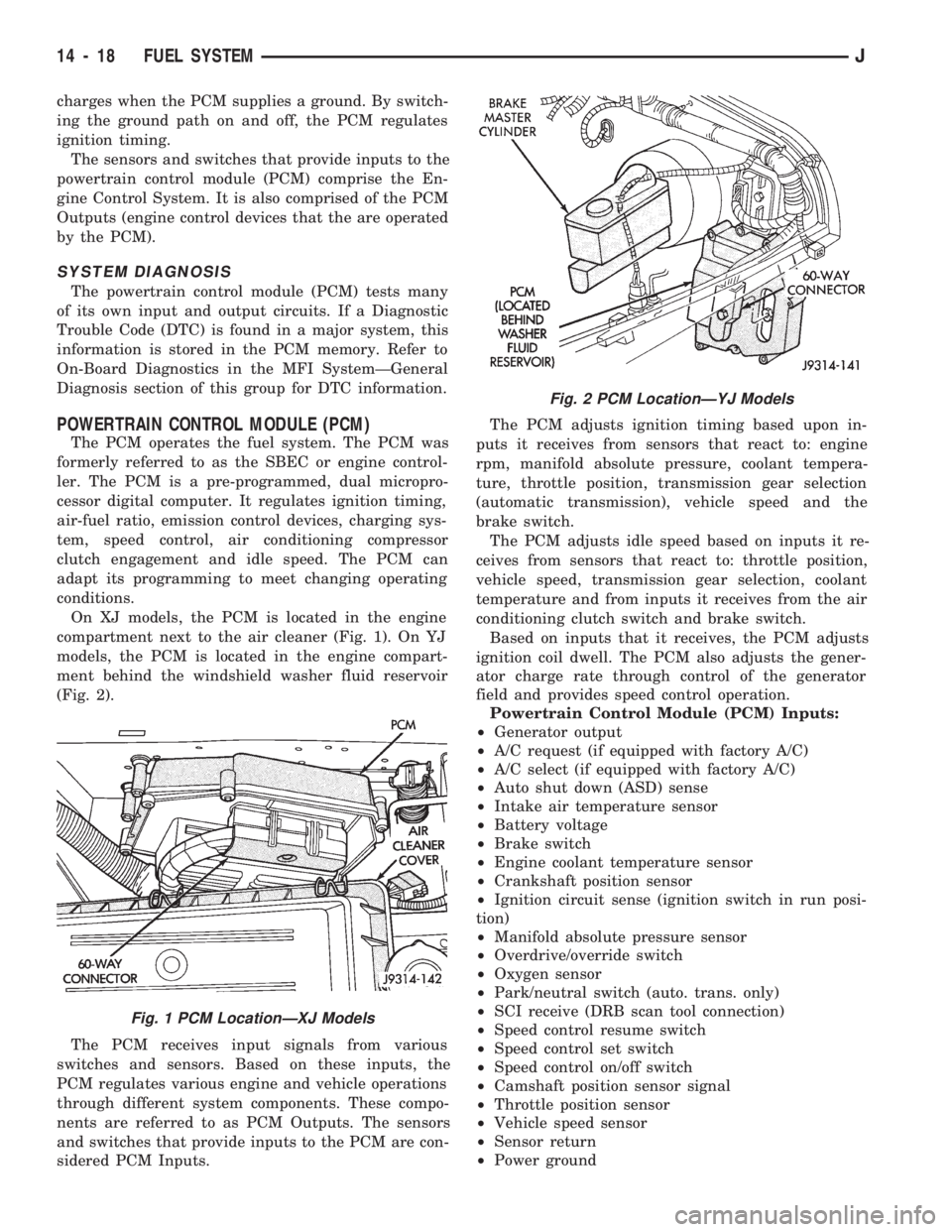
On XJ models, the PCM is located in the engine
compartment next to the air cleaner (Fig. 1). On YJ
models, the PCM is located in the engine compart-
ment behind the windshield washer fluid reservoir
(Fig. 2).
The PCM receives input signals from various
switches and sensors. Based on these inputs, the
PCM regulates various engine and vehicle operations
through different system components. These compo-
nents are referred to as PCM Outputs. The sensors
and switches that provide inputs to the PCM are con-
sidered PCM Inputs.The PCM adjusts ignition timing based upon in-
puts it receives from sensors that react to: engine
rpm, manifold absolute pressure, coolant tempera-
ture, throttle position, transmission gear selection
(automatic transmission), vehicle speed and the
brake switch.
The PCM adjusts idle speed based on inputs it re-
ceives from sensors that react to: throttle position,
vehicle speed, transmission gear selection, coolant
temperature and from inputs it receives from the air
conditioning clutch switch and brake switch.
Based on inputs that it receives, the PCM adjusts
ignition coil dwell. The PCM also adjusts the gener-
ator charge rate through control of the generator
field and provides speed control operation.
Powertrain Control Module (PCM) Inputs:
²Generator output
²A/C request (if equipped with factory A/C)
²A/C select (if equipped with factory A/C)
²Auto shut down (ASD) sense
²Intake air temperature sensor
²Battery voltage
²Brake switch
²Engine coolant temperature sensor
²Crankshaft position sensor
²Ignition circuit sense (ignition switch in run posi-
tion)
²Manifold absolute pressure sensor
²Overdrive/override switch
²Oxygen sensor
²Park/neutral switch (auto. trans. only)
²SCI receive (DRB scan tool connection)
²Speed control resume switch
²Speed control set switch
²Speed control on/off switch
²Camshaft position sensor signal
²Throttle position sensor
²Vehicle speed sensor
²Sensor return
²Power ground
Fig. 1 PCM LocationÐXJ Models
Fig. 2 PCM LocationÐYJ Models
14 - 18 FUEL SYSTEMJ
Page 1180 of 1784
30RH/32RH TRANSMISSION DIAGNOSIS
INDEX
page page
Air Pressure Test........................ 73
Analyzing the Road Test................... 70
Converter Housing Leak Diagnosis........... 73
Converter Stall Test...................... 72
Diagnosis Guides and Charts............... 76
Fluid Level and Condition.................. 69Gearshift Linkage........................ 70
General Information....................... 69
Hydraulic Pressure Test................... 71
Preliminary Diagnosis..................... 69
Road Test.............................. 70
Transmission Throttle Valve Cable Adjustment . . 70
GENERAL INFORMATION
Automatic transmission problems are generally the
result of:
²poor engine performance
²incorrect fluid level
²incorrect cable/linkage adjustment
²incorrect band adjustment
²incorrect hydraulic control pressure adjustments
²hydraulic component malfunctions
²mechanical component malfunctions.
Begin diagnosis by checking the easily accessible
items such as fluid level, fluid condition and control
linkage adjustment. A road test will determine if fur-
ther diagnosis is necessary.
Procedures outlined in this section should be per-
formed in the following sequence to realize the most
accurate results:
²Preliminary diagnosis
²Check fluid Level and condition
²Check control linkage Adjustment
²Road test
²Stall test
²Hydraulic pressure test
²Air pressure tests
²Leak Tests
²Analyze test results and consult diagnosis charts
PRELIMINARY DIAGNOSIS
Two basic procedures are required. One procedure
for vehicles that are driveable and an alternate pro-
cedure for disabled vehicles (will not back up or
move forward).
Vehicle Is Driveable
(1) Check fluid level and condition.
(2) Adjust throttle cable and gearshift linkage if
complaint was based on delayed, erratic, or harsh
shifts.
(3) Road test vehicle and note transmission operat-
ing characteristics.
(4) Perform stall test if complaint is based on slug-
gish, low speed acceleration or abnormal throttle
opening needed to maintain normal speeds with
properly tuned engine.
(5) Perform hydraulic pressure tests.(6) Perform air pressure test to check clutch-band
operation.
Vehicle Is Disabled
(1) Check fluid level and condition.
(2) Check for broken, disconnected throttle link-
age.
(3) Check for cracked, leaking cooler lines, or
loose, missing pressure port plugs.
(4) Raise vehicle, start engine, shift transmission
into gear and note following:
(a) If propeller shafts turn but wheels do not,
problem is with differential or axle shafts.
(b) If propeller shafts do not turn and transmis-
sion is noisy, stop engine. Remove oil pan, and
check for debris. If pan is clear, remove transmis-
sion and check for damaged drive plate, converter,
oil pump or input shaft.
(c) If propeller shafts do not turn and transmis-
sion is not noisy, perform hydraulic pressure test to
determine if problem is a hydraulic or mechanical.
FLUID LEVEL AND CONDITION
(1) Position vehicle on level surface. This is impor-
tant in obtaining an accurate fluid level check.
(2) To avoid false readings, which could produce
under or over fill condition, do not check level until
fluid is at normal operating temperature.
(3) Shift transmission into Neutral.
(4) Apply parking brakes.
(5) Operate engine at curb idle speed.
WARNING: WHEN PERFORMING UNDERHOOD OP-
ERATIONS WITH THE ENGINE RUNNING, KEEP
YOUR HANDS WELL AWAY FROM HOT OR ROTAT-
ING ENGINE COMPONENTS. DO NOT WEAR
LOOSE ARTICLES OF CLOTHING WHICH COULD
BECOME ENTANGLED IN ENGINE COMPONENTS
OR ACCESSORIES.
(6) Clean dipstick filler cap and tube before remov-
ing dipstick.
(7) Remove dipstick and inspect fluid level.
²Correct level is to FULL mark
²Acceptable level is between ADD and FULL marks
J30RH/32RH TRANSMISSION DIAGNOSIS 21 - 69
Page 1184 of 1784
STALL TEST PROCEDURE
(1) Connect tachometer to engine.
(2) Check and adjust transmission fluid level.
(3) Start and run engine until transmission fluid
reaches normal operating temperature.
(4) Block front wheels.
(5) Fully apply service and parking brakes.
(6) Open throttle completely for no more than five
seconds and record maximum engine rpm registered
on tachometer.
CAUTION: Stall testing causes a rapid increase in
transmission fluid temperature. Do not hold the
throttle open any longer than five seconds. If more
than one stall test is required, run the engine at
1000 rpm with the transmission in Neutral for at
least 20 seconds to cool the fluid.
(7) If engine speed exceeds maximum shown in
stall speed chart, release accelerator immediately.
This indicates that transmission clutch slippage is
occurring.
(8) Shift transmission into Neutral. Run engine for
20 seconds to cool fluid. Then stop engine, shift
transmission into Park and release brakes.
(9) Stall speeds should be in 1700-2000 rpm range.
(10) Refer to Stall Test Diagnosis.
STALL TEST DIAGNOSIS
Stall Speed Too High
If the stall speed exceeds specifications by more
than 200 rpm, transmission clutch slippage is indi-
cated.
Stall Speed Too Low
Low stall speeds with a properly tuned engine in-
dicate a torque converter overrunning clutch prob-
lem. The condition should be confirmed by road
testing prior to converter replacement.
The converter overrunning clutch is slipping when
stall speeds are 250 to 350 rpm below specified min-
imum. And when the vehicle operates properly at
highway speeds but has poor low speed acceleration.
Stall Speed Normal
If stall speeds are normal but abnormal throttle
opening is required to maintain highway speeds, the
converter overrunning clutch is seized and the torque
converter must be replaced.
Converter Noise During Test
A whining noise caused by fluid flow is normal
during a stall test. However, loud metallic noises in-
dicate a damaged converter. To confirm that noise is
originating from the converter, operate the vehicle at
light throttle in Drive and Neutral on a hoist and lis-
ten for noise coming from the converter housing.
AIR PRESSURE TEST
Air pressure testing can be used to check clutch
and band operation with the transmission either in
the vehicle, or on the work bench as a final check af-
ter overhaul.
Air pressure testing requires that the oil pan and
valve body be removed from the transmission.
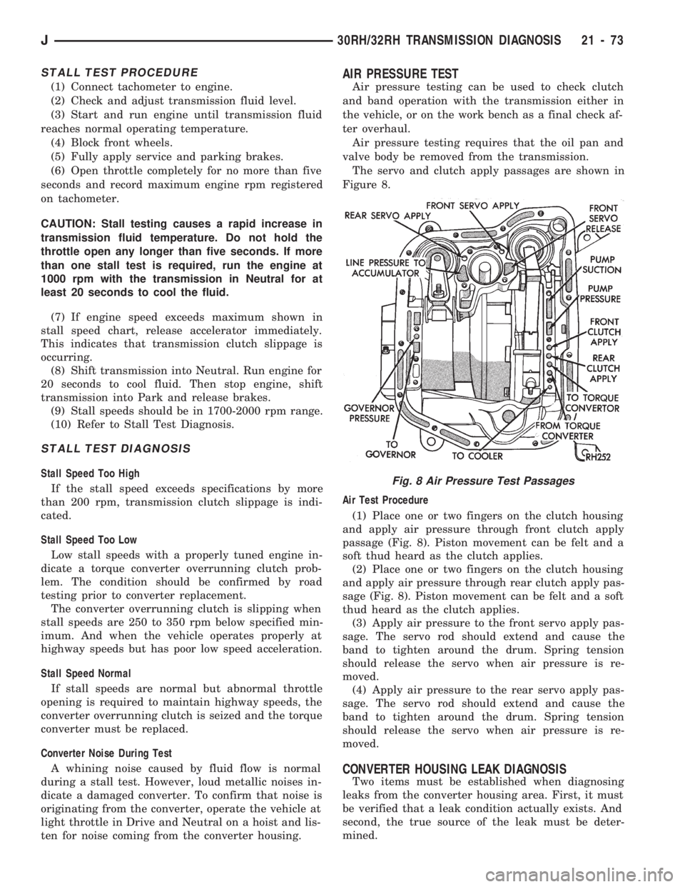
The servo and clutch apply passages are shown in
Figure 8.
Air Test Procedure
(1) Place one or two fingers on the clutch housing
and apply air pressure through front clutch apply
passage (Fig. 8). Piston movement can be felt and a
soft thud heard as the clutch applies.
(2) Place one or two fingers on the clutch housing
and apply air pressure through rear clutch apply pas-
sage (Fig. 8). Piston movement can be felt and a soft
thud heard as the clutch applies.
(3) Apply air pressure to the front servo apply pas-
sage. The servo rod should extend and cause the
band to tighten around the drum. Spring tension
should release the servo when air pressure is re-
moved.
(4) Apply air pressure to the rear servo apply pas-
sage. The servo rod should extend and cause the
band to tighten around the drum. Spring tension
should release the servo when air pressure is re-
moved.
CONVERTER HOUSING LEAK DIAGNOSIS
Two items must be established when diagnosing
leaks from the converter housing area. First, it must
be verified that a leak condition actually exists. And
second, the true source of the leak must be deter-
mined.
Fig. 8 Air Pressure Test Passages
J30RH/32RH TRANSMISSION DIAGNOSIS 21 - 73