1994 JEEP CHEROKEE brake fluid
[x] Cancel search: brake fluidPage 154 of 1784
SERVICE BRAKE DIAGNOSIS
INDEX
page page
Component Inspection...................... 8
Diagnosing Parking Brake Problems.......... 10
Diagnosing Service Brake Problems........... 8
Diagnosis Procedures...................... 7
General Information........................ 7Master Cylinder/Power Booster Test.......... 11
Power Booster Check Valve Test............ 11
Power Booster Vacuum Test................ 12
Preliminary Brake Check.................... 7
Road Testing............................ 7
GENERAL INFORMATION
The diagnosis information in this section covers
service brake components which include:
²disc brake calipers
²disc brakeshoes
²drum brake wheel cylinders
²drum brakeshoes and brake drums
²drum brake support plates
²parking brake mechanism
²master cylinder/combination valve
²vacuum power brake booster
²brake pedal and brakelight switch
²brake warning light
DIAGNOSIS PROCEDURES
Service brake diagnosis involves determining if a
problem is related to a mechanical, hydraulic or vac-
uum operated component. A preliminary brake
check, followed by road testing and component in-
spection are needed to determine a problem cause.
Road testing will either verify proper brake opera-
tion or confirm the existence of a problem. Compo-
nent inspection will, in most cases, identify the
actual part responsible for a problem.
The first diagnosis step is the preliminary brake
check. This involves inspecting fluid level, parking
brake action, wheel and tire condition, checking for
obvious leaks or component damage and testing
brake pedal response. A road test will confirm or
deny the existence of a problem. The final diagnosis
procedure involves road test analysis and a visual in-
spection of brake components.
PRELIMINARY BRAKE CHECK
(1) If amber antilock light is illuminated, refer to
Antilock Brake System Diagnosis. However, if red
warning light is illuminated, or if neither warning
light is illuminated, continue with diagnosis.
(2) Check condition of tires and wheels. Damaged
wheels and worn, damaged, or underinflated tires
can cause pull, shudder, tramp and a condition simi-
lar to grab.
(3) If complaint was based on noise when braking,
check suspension components. Jounce front and rearof vehicle and listen for noise that might be caused
by loose, worn, or damaged suspension or steering
components.
(4) Inspect brake fluid level:
(a) If vehicle has one-piece master cylinder, fluid
level should be to 6 mm (1/4 in.) of reservoir rim. If
vehicle two-piece, removable reservoir, correct level
is to top of indicator rings in reservoir.
(b) On models with ABS brakes, preferred level
is to MAX mark on reservoir. Acceptable level is
between MAX and MIN marks.
(c) Remember that fluid level in the front and
rear reservoir compartments will decrease in pro-
portion to normal lining wear. However, if fluid
level is abnormally low, look for leaks at calipers,
wheel cylinders, brakelines and master cylinder.
(5) Inspect brake fluid condition:
(a) Fluid should be reasonably clear and free of
foreign material.Note that brake fluid tends to
darken over time. This is normal and should
not be mistaken for contamination. If fluid is
clear of foreign material, it is OK.
(b) If fluid is highly discolored, or appears to con-
tain foreign material, drain out a sample with a
clean suction gun. Pour sample in a glass container
and note condition.
(c) If fluid separates into layers, obviously con-
tains oil, or a substance other than brake fluid,
system seals and cups will have to be replaced and
hydraulic system flushed.
(6) Check parking brake operation. Verify free
movement and full release of cables and foot pedal or
hand lever. Also note if vehicle was being operated
with parking brake partially applied.
(7) Check brake pedal operation. Verify that pedal
does not bind and has adequate free play. If pedal
lacks free play, check pedal and power booster for be-
ing loose or for bind condition. Do not road test until
condition is corrected.
(8) If components inspected look OK, road test the
vehicle.
ROAD TESTING
(1) If amber warning light is illuminated, problem
is with antilock system component. Refer to Antilock
Brake System Diagnosis.
JBRAKES 5 - 7
Page 155 of 1784
(2) If red warning light is illuminated, or if neither
warning light is illuminated, make several stops and
note pedal action and brake response.
(3) Check brake pedal response with transmission
in Neutral and engine running. Pedal should remain
firm under steady foot pressure. If pedal falls away,
problem is either in vacuum booster or master cylin-
der.
(4) During road test, make normal and firm brake
stops in 25-40 mph range. Note faulty brake opera-
tion such as pull, grab, drag, noise, fade, pedal pul-
sation, etc.
(5) Inspect suspect brake components and refer to
problem diagnosis information for causes of various
brake conditions.
COMPONENT INSPECTION
Fluid leak points and dragging brake units can
usually be located without removing any compo-
nents. The area around a leak point will be wet with
fluid. The components at a dragging brake unit
(wheel, tire, rotor) will be quite warm or hot to the
touch.
Other brake problem conditions will require compo-
nent removal for proper inspection. Raise the vehicle
and remove the necessary wheels for better visual ac-
cess.
During component inspection, pay particular atten-
tion to heavily rusted/corroded brake components
(e.g. rotors, caliper pistons, brake return/holddown
springs, support plates, etc.).
Heavy accumulations of rust may be covering se-
vere damage to a brake component. It is wise to re-
move surface rust in order to accurately determine
the depth of rust penetration and damage. Light sur-
face rust is fairly normal and not a major concern (as
long as it is removed). However, heavy rust buildup,
especially on high mileage vehicles may cover struc-
tural damage to such important components as
brakelines, rotors, support plates, and brake boosters.
Refer to the wheel brake service procedures in this
group for more information.
DIAGNOSING SERVICE BRAKE PROBLEMS
BRAKE WARNING LIGHT OPERATION
The red brake warning light will illuminate under
the following conditions:
²for 2-3 seconds at startup as part of normal bulb
check
²parking brakes applied
²low pedal caused by malfunction in front/rear
brake hydraulic circuit (differential switch valve ac-
tuated)
If the red light remains on after startup, first ver-
ify that the parking brakes are fully released. Then
check pedal action and fluid level. A red light indi-
cates that the valve in the differential pressureswitch has been actuated. If a problem is confirmed,
inspect the hydraulic system and wheel brake compo-
nents.
On models with ABS brakes, the amber warning
light only illuminates when an ABS component has
malfunctioned. The ABS light operates indepen-
dently of the red warning light. Refer to the antilock
brake section for more detailed diagnosis informa-
tion.
PEDAL FALLS AWAY
A brake pedal that falls away under steady foot
pressure is generally the result of a system leak. The
leak point could be at a brakeline, fitting, hose,
wheel cylinder, or caliper. Internal leakage in the
master cylinder caused by worn or damaged piston
cups, may also be the problem cause.
If leakage is severe, fluid will be evident at or
around the leaking component. However internal
leakage in the master cylinder will not be physically
evident. Refer to the cylinder test procedure in this
section.
LOW PEDAL
If a low pedal is experienced, pump the pedal sev-
eral times. If the pedal comes back up, worn lining
and worn rotors or drums are the most likely causes.
However, if the pedal remains low and/or the warn-
ing light illuminates, the problem is in the master
cylinder, wheel cylinders, or calipers.
A decrease in master cylinder fluid level may only
be the result of normal lining wear. Fluid level will
decrease as lining wear occurs. It is a result of the
outward movement of caliper and wheel cylinder pis-
tons to compensate for normal wear.
SPONGY PEDAL
A spongy pedal is most often caused by air in the
system. However, thin drums or substandard brake
lines and hoses will also cause a condition similar to
a spongy pedal. The proper course of action is to
bleed the system, or replace thin drums and suspect
quality brake lines and hoses.
HARD PEDAL OR HIGH PEDAL EFFORT
A hard pedal or high pedal effort may be due to
lining that is water soaked, contaminated, glazed, or
badly worn. The power booster or check valve could
also be faulty. Test the booster and valve as de-
scribed in this section.
BRAKE DRAG
Brake drag occurs when the lining is in constant
contact with the rotor or drum. Drag can occur at
one wheel, all wheels, fronts only, or rears only. It is
a product of incomplete brakeshoe release. Drag can
be minor or severe enough to overheat the linings,
rotors and drums.
5 - 8 BRAKESJ
Page 156 of 1784

Brake drag also has a direct effect on fuel economy.
If undetected, minor brake drag can be misdiagnosed
as an engine or transmission/torque converter prob-
lem.
Minor drag will usually cause slight surface char-
ring of the lining. It can also generate hard spots in
rotors and drums from the overheat/cool down pro-
cess. In most cases, the rotors, drums, wheels and
tires are quite warm to the touch after the vehicle is
stopped.
Severe drag can char the brake lining all the way
through. It can also distort and score rotors and
drums to the point of replacement. The wheels, tires
and brake components will be extremely hot. In se-
vere cases, the lining may generate smoke as it chars
from overheating.
An additional cause of drag involves the use of in-
correct length caliper mounting bolts. Bolts that are
too long can cause a partial apply condition. The cor-
rect caliper bolts have a shank length of 67 mm
(2.637 in.), plus or minus 0.6 mm (0.0236 in.). Refer
to the Disc Brake service section for more detail on
caliper bolt dimensions and identification.
Some common causes of brake drag are:
²loose or damaged wheel bearing
²seized or sticking caliper or wheel cylinder piston
²caliper binding on bushings or slide surfaces
²wrong length caliper mounting bolts (too long)
²loose caliper mounting bracket
²distorted brake drum or shoes
²rear brakeshoes binding on worn/damaged support
plates
²severely rusted/corroded components
²misassembled components.
If brake drag occurs at all wheels, the problem may
be related to a blocked master cylinder compensator
port or faulty power booster (binds-does not release).
The brakelight switch can also be a cause of drag.
An improperly mounted or adjusted brakelight
switch can prevent full brake pedal return. The re-
sult will be the same as if the master cylinder com-
pensator ports are blocked. The brakes would be
partially applied causing drag.
BRAKE FADE
Brake fade is a product of overheating caused by
brake drag. However, overheating and subsequent
fade can also be caused by riding the brake pedal,
making repeated high deceleration stops in a short
time span, or constant braking on steep roads. Refer
to the Brake Drag information in this section for
causes.
PEDAL PULSATION
Pedal pulsation is caused by components that are
loose, or beyond tolerance limits.
Disc brake rotors with excessive lateral runout or
thickness variation, or out of round brake drums arethe primary causes of pulsation. Other causes are
loose wheel bearings or calipers and worn, damaged
tires.
PULL
A front pull condition could be the result of:
²contaminated lining in one caliper
²seized caliper piston
²binding caliper
²wrong caliper mounting bolts (too long)
²loose caliper
²loose or corroded mounting bolts
²improper brakeshoes
²damaged rotor
²incorrect wheel bearing adjustment (at one wheel)
A worn, damaged wheel bearing or suspension
component are further causes of pull. A damaged
front tire (bruised, ply separation) can also cause
pull. Wrong caliper bolts (too long) will cause a par-
tial apply condition and pull if only one caliper is in-
volved.
A common and frequently misdiagnosed pull condi-
tion is where direction of pull changes after a few
stops. The cause is a combination of brake drag fol-
lowed by fade at the dragging brake unit.
As the dragging brake overheats, efficiency is so
reduced that fade occurs. If the opposite brake unit is
still functioning normally, its braking effect is mag-
nified. This causes pull to switch direction in favor of
the brake unit that is functioning normally.
When diagnosing a change in pull condition, re-
member that pull will return to the original direction
if the dragging brake unit is allowed to cool down
(and is not seriously damaged).
REAR BRAKE GRAB
Rear grab (or pull) is usually caused by contami-
nated lining, bent or binding shoes and support
plates, or improperly assembled components. This is
particularly true when only one rear wheel is in-
volved. However, when both rear wheels are affected,
the master cylinder or proportioning valve could be
at fault.
BRAKES DO NOT HOLD AFTER DRIVING
THROUGH DEEP WATER PUDDLES
This condition is generally caused by water soaked
lining. If the lining is only wet, it can be dried by
driving with the brakes lightly applied for a mile or
two. However, if the lining is both wet and dirty, dis-
assembly and cleaning will be necessary.
BRAKE FLUID CONTAMINATION
There are two basic causes of brake fluid contami-
nation. The first involves allowing dirt, debris, or
other liquid materials to enter the cylinder reservoirs
JBRAKES 5 - 9
Page 157 of 1784

when the cover is off. The second involves adding to,
or filling the cylinder reservoirs with a non-recom-
mended fluid.
Brake fluid contaminated with only dirt, or debris
usually retains a normal appearance. In some cases,
the foreign material will remain suspended in the
fluid and be visible. The fluid and foreign material
can be removed from the reservoir with a suction
gun but only if the brakes have not been applied. If
the brakes are applied after contamination, system
flushing will be required. The master cylinder may
also have to be disassembled, cleaned and the piston
seals replaced. Foreign material lodged in the reser-
voir compensator/return ports can cause brake drag
by restricting fluid return after brake application.
Brake fluid contaminated by a non-recommended
fluid will usually be discolored, milky, oily looking,
or foamy. In some cases, it may even appear as if the
fluid contains sludge.However, remember that
brake fluid will darken in time and occasionally
be cloudy in appearance. These are normal con-
ditions and should not be mistaken for contami-
nation.
If some type of oil has been added to the system,
the fluid will separate into distinct layers. To verify
this, drain off a sample with a clean suction gun.
Then pour the sample into a glass container and ob-
serve fluid action. If the fluid separates into distinct
layers, it is definitely contaminated.
The only real correction for contamination by non-
recommended fluid is to flush the entire hydraulic
system and replace all the seals.
BRAKE NOISE
Squeak/Squeal
Brake squeak or squeal may be due to linings that
are wet or contaminated with brake fluid, grease, or
oil. Glazed linings and rotors with hard spots can
also contribute to squeak. Dirt and foreign material
embedded in the brake lining will also cause squeak/
squeal.
A very loud squeak or squeal is frequently a sign
of severely worn brake lining. If the lining has worn
through to the brakeshoes in spots, metal-to-metal
contact occurs. If the condition is allowed to continue,
rotors can become so scored that replacement is nec-
essary.
Thump/Clunk
Thumping or clunk noises during braking are fre-
quentlynotcaused by brake components. In many
cases, such noises are caused by loose or damaged
steering, suspension, or engine components. How-
ever, calipers that bind on the slide surfaces can gen-
erate a thump or clunk noise. In addition, worn out,
improperly adjusted, or improperly assembled rear
brakeshoes can also produce a thump noise.Chatter/Shudder
Brake chatter, or shudder is usually caused by
loose or worn components, or glazed/burnt lining. Ro-
tors with hard spots can also contribute to chatter.
Additional causes of chatter are out of tolerance ro-
tors, brake lining not securely attached to the shoes,
loose wheel bearings and contaminated brake lining.
BRAKELINING CONTAMINATION
Brakelining contamination is usually a product of
leaking calipers or wheel cylinders, driving through
deep water puddles, or lining that has become cov-
ered with grease and grit during repair.
WHEEL AND TIRE PROBLEMS
Some conditions attributed to brake components
may actually be caused by a wheel or tire problem.
A damaged wheel can cause shudder, vibration and
pull. A worn or damaged tire can also cause pull.
Severely worn tires with very little tread left can
produce a condition similar to grab as the tire loses
and recovers traction.
Flat-spotted tires can cause vibration and wheel
tramp and generate shudder during brake operation.
A tire with internal damage such as a severe
bruise or ply separation can cause pull and vibration.
DIAGNOSING PARKING BRAKE PROBLEMS
Adjustment Mechanism
Parking brake adjustment is controlled by a
cable tensioner mechanism. This applies to 1991
through 1994 YJ models and 1992 and later XJ
models. The cable tensioner, once adjusted at
the factory, will not need further adjustment un-
der normal circumstances. There are only two
instances when adjustment is required. The first
is when a new tensioner, or cables have been in-
stalled. And the second, is when the tensioner
and cables are disconnected for access to other
brake components.
Parking Brake problem Causes
In most cases, the actual cause of an improperly
functioning parking brake (too loose/too tight/wont
hold), can be traced to a drum brake component.
The leading cause of improper parking brake
operation, is excessive clearance between the
brakeshoes and the drum surface. Excessive
clearance is a result of: lining and/or drum wear;
oversize drums; or inoperative shoe adjuster
components.
Excessive parking brake lever travel (sometimes
described as a loose lever or too loose condition), is
the result of worn brakeshoes/drums, improper
brakeshoe adjustment, or mis-assembled brake parts.
A ``too loose'' condition can also be caused by inop-
erative brakeshoe adjusters. If the adjusters are mis-
5 - 10 BRAKESJ
Page 160 of 1784
BRAKE BLEEDINGÐBRAKE FLUID AND LEVELÐBRAKELINES AND HOSES
INDEX
page page
Brake BleedingÐXJ/YJ with ABS Brakes....... 14
Brake BleedingÐXJ/YJ with Standard Brakes . . . 13
Brake Fluid Contamination.................. 13
Brake Fluid Level........................ 13Brakeline Charts......................... 15
Brakelines and Hoses..................... 15
Combination Valve....................... 15
Recommended Brake Fluid................. 13
RECOMMENDED BRAKE FLUID
The only brake fluid recommended for Jeep vehi-
cles with standard or antilock brakes, is Mopar brake
fluid, or an equivalent fluid meeting SAE J1703 and
DOT 3 standards.
Use new brake fluid only to top off the master
cylinder or refill the system. Never use re-
claimed fluid, fluid not meeting the SAE/DOT
standards or fluid from an unsealed container.
Do not use fluid from any container that has
been left open for any length of time. Fluid in
open containers can absorb moisture.
BRAKE FLUID LEVEL
Always clean the master cylinder and cover before
checking fluid level. If not cleaned, dirt from the
cover could enter the fluid. Also check the cover seal
and replace it if torn or distorted.
Correct fluid level is to within 6 mm (1/4 in.) of the
reservoir rim, or to the fill mark on models with a
plastic reservoir. Refer to the Antilock Brake section
for fluid levels on models equipped with ABS brakes.
BRAKE FLUID CONTAMINATION
Oil in the fluid will cause brake system rubber
seals to soften and swell. The seals may also become
porous and begin to deteriorate.
If fluid contamination is suspected, drain off a sam-
ple from the master cylinder. A suction gun or simi-
lar device can be used for this purpose.
Empty the drained fluid into a glass container.
Contaminants in the fluid will cause the fluid to sep-
arate into distinct layers. If contamination has oc-
curred, the system rubber seals, hoses and cups must
be replaced and the system thoroughly flushed with
clean brake fluid.
BRAKE BLEEDINGÐXJ/YJ WITH STANDARD
BRAKES
Use Mopar DOT 3 brake fluid, or an equivalent
meeting SAE/DOT standards J1703-F and DOT 3, to
fill and bleed the system.
On standard brake models, bleeding can be per-
formed either manually or with pressure equipment.
However, if pressure equipment is used, it will be
necessary to hold the front brake metering valveopen in order to bleed the front brakes. The valve
can be held open with a tension clip tool or by hand.
It will also be necessary that a suitable size pressure
tank hose adapter be available for use on the master
cylinder.
MANUAL BLEEDING PROCEDURE
(1) If master cylinder has been overhauled or a
new cylinder will be installed, bleed cylinder on
bench before installation. This shortens time needed
to bleed system and ensures proper cylinder opera-
tion.
(2) Wipe master cylinder reservoir and cap clean
with shop towels.
(3) Remove cover and fill master cylinder reservoir
with Mopar, or equivalent DOT 3 brake fluid.
(4) Open all caliper and wheel cylinder bleed
screws.
(5) Close bleed screws after fluid begins flowing
from each bleed screw.
(6) Top off master cylinder reservoir again.
(7) Use following bleed sequence:
²master cylinder
²right rear
²left rear
²right front
²left front
(8) Observe following brake bleeding precautions:
²Do not pump brake pedal at any time while bleed-
ing. Air in system will be compressed into small bub-
bles that are distributed throughout hydraulic
system. This will make a second and third bleeding
operation necessary.
²Bleed only one wheel brake unit at a time and use
a bleed hose to bleed each wheel brake unit (Fig. 7).
²Attach one end of bleed hose to bleed screw and in-
sert opposite end in glass container partially filled
with brake fluid (Fig. 7). Glass container makes it
easier to see air bubbles as they exit the bleed hose.
²Be sure end of bleed hose is immersed in fluid. Im-
mersing hose end in fluid prevents air from being
drawn back into cylinder and brakeline.
(9) Bleed master cylinder first. Have helper oper-
ate brake pedal while bleeding each master cylinder
fluid outlet line.
JBRAKES 5 - 13
Page 161 of 1784
CAUTION: Do not allow the master cylinder to run
out of fluid when bleeding the brakes. An empty
cylinder will allow additional air to be drawn into
the system. Check the cylinder fluid level frequently
and add fluid as needed.
(10) Bleed each wheel brake unit as follows:
(a) Open caliper or wheel cylinder bleed fitting
1/2 to 3/4 turn.
(b) Have helper press and hold brake pedal to
floor.Do not pump brake pedal while bleeding.
Air in system will be compressed into small
bubbles that are distributed throughout hy-
draulic system. This will make a second and
third bleeding operation necessary.
(c) Tighten bleed fitting and have helper release
brake pedal. Continue bleeding operation until
fluid entering bleed container is clear and free of
bubbles.
(d) Repeat bleeding operation at remaining
wheel brake units.
(e) Discard fluid bled into glass container. It
should not be reused.
(11) Check and adjust master cylinder fluid level.
(12) Verify proper brake operation before moving
vehicle.
PRESSURE BLEEDING
The front brake metering valve is located in the
forward end of the combination valve. The valve
stem is accessible from the same end of the valve.
The stem must be either pressed inward, or held out-
ward slightly in order to bleed the front brakes.
(1) Fill bleeder tank if necessary.
(2) Purge air from bleeder tank and lines before
proceeding.(3) Wipe master cylinder cover clean.
(4) Remove master cylinder cover and install pres-
sure hose adapter in place of cover. A suitable
adapter will usually be available from tank manufac-
turer.
(5) Connect bleeder tank pressure hose to adapter.
(6) Bleed master cylinder first. Then bleed rear
brakes as described in manual bleeding procedure.
(7) Bleed front brakes as described in manual
bleeding procedure. Have helper hold metering valve
open by pressing valve stem inward slightly. Amount
of valve stem movement needed to hold valve open is
quite modest. Do not use excessive force.
(8) Remove pressure bleeding equipment and top
off master cylinder reservoir.
BRAKE BLEEDINGÐXJ/YJ WITH ABS BRAKES
A different bleeding method is required for the
ABS system. It is basically a three step process
consisting of: A conventional manual brake
bleed. A second bleed using the DRB II, fol-
lowed by a repeat of the conventional manual
bleed procedure. Recommended ABS bleeding
procedure is as follows:
(1) Clean master cylinder reservoir caps and reser-
voir exterior. Dirt, foreign material on the caps and
reservoir must not be allowed to enter reservoir.
(2) Fill reservoir with Mopar brake fluid, or equiv-
alent quality fluid meeting SAE 1703 and DOT 3
standards.
(3) Recommended bleeding sequence is:
²master cylinder
²HCU valve body (at fluid lines)
²right rear wheel
²left rear wheel
²right front wheel
²left front wheel.
(4) Attach bleed hose to caliper or wheel cylinder
bleed fitting. Immerse end of bleed hose in glass con-
tainer partially filled with brake fluid. Be sure hose
end is submerged in fluid (Fig. 7).
(5) Bleed each wheel brake unit as follows:
(a) Have helper apply and hold brake pedal.
(b) Open bleed screw 1/2 turn. Close bleed screw
when brake pedal contacts floorpan.Do not pump
brake pedal at any time while bleeding. This
compresses air into small bubbles which are
distributed throughout system. Additional
bleeding operations will then be necessary to
remove all trapped air from the system.
(c) Repeat bleeding operation 5-7 more times at
each rear wheel brake unit.
(d) Continue bleeding until fluid entering glass
container is free of air bubbles. Check reservoir
fluid level frequently and add fluid if necessary.
(e) Repeat bleeding procedures at front wheels.
Fig. 7 Typical Bleed Hose And Fluid Container
5 - 14 BRAKESJ
Page 162 of 1784
CAUTION: Do not allow the master cylinder reser-
voir to run dry while bleeding the brakes. Running
dry will allow air to re-enter the system making a
second bleeding operation necessary.
(6) Perform ``Bleed Brake'' procedure with DRB II
scan tool. Procedure is described in DRB II software
information and diagnostic manual.
(a) Connect DRB II scan tool to diagnostic con-
nector.
(b) Run Bleed Brake procedure as described in
tester manual.
(7) Repeat conventional bleeding procedure out-
lined in steps (1) through (8).
(8) Top off master cylinder fluid level if necessary.
(9) Verify proper brake operation.
BRAKELINES AND HOSES
Metal brakelines and rubber brake hoses should be
inspected periodically and replaced if damaged.
Rubber brake hoses should be replaced if cut,
cracked, swollen, or leaking. Rubber hoses must be
replaced. They are not repairable parts.
When installing new, or original brakelines andhoses, lubricate the fitting threads with brake fluid
before connection.
The steel brakelines should be checked every time
the vehicle is in for normal maintainence. This is im-
portant on high mileage vehicles. It is even more im-
portant when a vehicle is operated in areas where
salt is used regularly on the road surface during win-
ter.
Heavily rusted/corroded brake rotors, drums, sup-
port plates, and brakelines should be cleaned and
carefully inspected. Heavy rust buildup can hide se-
vere damge to a component. Severely rusted parts
should be replaced if you are unsure about their con-
dition.
COMBINATION VALVE
The combination valve is not a serviceable part.
The valve must be replaced if a malfunction occurs.
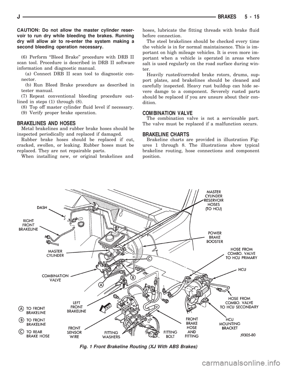
BRAKELINE CHARTS
Brakeline charts are provided in illustration Fig-
ures 1 through 8. The illustrations show typical
brakeline routing, hose connections and component
position.
Fig. 1 Front Brakeline Routing (XJ With ABS Brakes)
JBRAKES 5 - 15
Page 167 of 1784
STANDARD MASTER CYLINDER
INDEX
page page
General Service Information................ 20
Master Cylinder Installation................. 20Master Cylinder Overhaul.................. 20
Master Cylinder Removal.................. 20
GENERAL SERVICE INFORMATION
The service information in this section covers the
standard (non-ABS) master cylinder only. The center
feed master cylinder used with the ABS system is
covered in the antilock brake component service sec-
tion.
MASTER CYLINDER REMOVAL
(1) Disconnect brake lines at master cylinder.
(2) Remove cylinder mounting nuts and remove
master cylinder.
(3) Remove cylinder cover and drain fluid.
MASTER CYLINDER INSTALLATION
(1) Bleed master cylinder on bench before installa-
tion. Refer to overhaul assembly procedure in this
section for bleeding method.
(2) Install cylinder on brake booster studs and in-
stall cylinder attaching nuts. Tighten nuts to 21 NIm
(15 ft. lbs.).
(3) Connect brakelines to cylinder.
(4) Fill and bleed brake system.
MASTER CYLINDER OVERHAUL
CYLINDER DISASSEMBLY
(1) Remove cylinder cover and drain fluid.
(2) Examine cylinder cover seal. Discard seal if
torn or distorted.
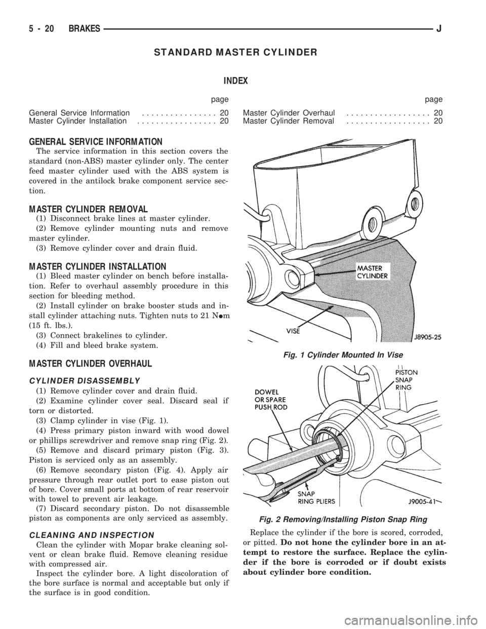
(3) Clamp cylinder in vise (Fig. 1).
(4) Press primary piston inward with wood dowel
or phillips screwdriver and remove snap ring (Fig. 2).
(5) Remove and discard primary piston (Fig. 3).
Piston is serviced only as an assembly.
(6) Remove secondary piston (Fig. 4). Apply air
pressure through rear outlet port to ease piston out
of bore. Cover small ports at bottom of rear reservoir
with towel to prevent air leakage.
(7) Discard secondary piston. Do not disassemble
piston as components are only serviced as assembly.
CLEANING AND INSPECTION
Clean the cylinder with Mopar brake cleaning sol-
vent or clean brake fluid. Remove cleaning residue
with compressed air.
Inspect the cylinder bore. A light discoloration of
the bore surface is normal and acceptable but only if
the surface is in good condition.Replace the cylinder if the bore is scored, corroded,
or pitted.Do not hone the cylinder bore in an at-
tempt to restore the surface. Replace the cylin-
der if the bore is corroded or if doubt exists
about cylinder bore condition.
Fig. 1 Cylinder Mounted In Vise
Fig. 2 Removing/Installing Piston Snap Ring
5 - 20 BRAKESJ