1994 JEEP CHEROKEE charging
[x] Cancel search: chargingPage 1667 of 1784
In the mid-position the gauge port is open. This po-
sition is used for pressure testing and for recovery of
the system.
DISCHARGE SERVICE VALVE ADAPTERS
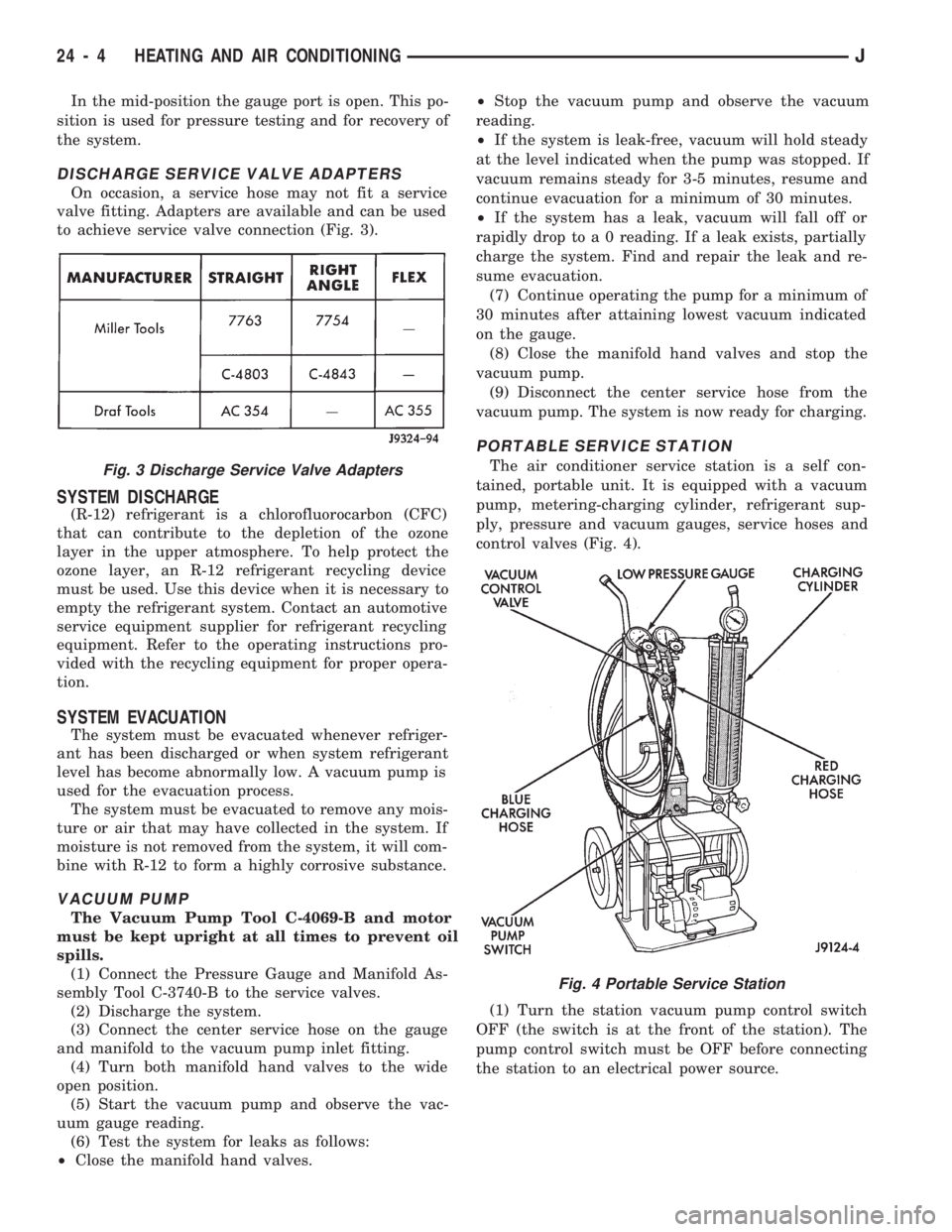
On occasion, a service hose may not fit a service
valve fitting. Adapters are available and can be used
to achieve service valve connection (Fig. 3).
SYSTEM DISCHARGE
(R-12) refrigerant is a chlorofluorocarbon (CFC)
that can contribute to the depletion of the ozone
layer in the upper atmosphere. To help protect the
ozone layer, an R-12 refrigerant recycling device
must be used. Use this device when it is necessary to
empty the refrigerant system. Contact an automotive
service equipment supplier for refrigerant recycling
equipment. Refer to the operating instructions pro-
vided with the recycling equipment for proper opera-
tion.
SYSTEM EVACUATION
The system must be evacuated whenever refriger-
ant has been discharged or when system refrigerant
level has become abnormally low. A vacuum pump is
used for the evacuation process.
The system must be evacuated to remove any mois-
ture or air that may have collected in the system. If
moisture is not removed from the system, it will com-
bine with R-12 to form a highly corrosive substance.
VACUUM PUMP
The Vacuum Pump Tool C-4069-B and motor
must be kept upright at all times to prevent oil
spills.
(1) Connect the Pressure Gauge and Manifold As-
sembly Tool C-3740-B to the service valves.
(2) Discharge the system.
(3) Connect the center service hose on the gauge
and manifold to the vacuum pump inlet fitting.
(4) Turn both manifold hand valves to the wide
open position.
(5) Start the vacuum pump and observe the vac-
uum gauge reading.
(6) Test the system for leaks as follows:
²Close the manifold hand valves.²Stop the vacuum pump and observe the vacuum
reading.
²If the system is leak-free, vacuum will hold steady
at the level indicated when the pump was stopped. If
vacuum remains steady for 3-5 minutes, resume and
continue evacuation for a minimum of 30 minutes.
²If the system has a leak, vacuum will fall off or
rapidly drop to a 0 reading. If a leak exists, partially
charge the system. Find and repair the leak and re-
sume evacuation.
(7) Continue operating the pump for a minimum of
30 minutes after attaining lowest vacuum indicated
on the gauge.
(8) Close the manifold hand valves and stop the
vacuum pump.
(9) Disconnect the center service hose from the
vacuum pump. The system is now ready for charging.
PORTABLE SERVICE STATION
The air conditioner service station is a self con-
tained, portable unit. It is equipped with a vacuum
pump, metering-charging cylinder, refrigerant sup-
ply, pressure and vacuum gauges, service hoses and
control valves (Fig. 4).
(1) Turn the station vacuum pump control switch
OFF (the switch is at the front of the station). The
pump control switch must be OFF before connecting
the station to an electrical power source.Fig. 3 Discharge Service Valve Adapters
Fig. 4 Portable Service Station
24 - 4 HEATING AND AIR CONDITIONINGJ
Page 1668 of 1784
(2) Close all the hand valves.
(3) Connect the red charging hose to the discharge
service valve.
(4) Connect the blue charging hose to the inlet
(suction) service valve.
(5) Discharge the system. Leave the suction and
discharge service valves in the mid-position.
CAUTION: The system must be completely dis-
charged into a recovery device before evacuating. If
the system is still charged, refrigerant can enter
and damage the vacuum pump.
(6) Connect the vacuum pump hose to the vacuum
pump inlet.
(7) Open the low and high pressure control valves
on the charging station.
(8) Start the vacuum pump. Open the vacuum con-
trol valve and note the vacuum reading.
(9) Test the system for leaks as follows:
²Close the manifold hand valves.
²Stop the vacuum pump and observe the vacuum
reading.
²If the system is leak-free, vacuum will hold steady
at the level indicated when the pump was stopped. If
vacuum remains steady for 3-5 minutes, resume and
continue evacuation for a minimum of 30 minutes.
²If the system has a leak, vacuum will fall off or
rapidly drop to a 0 reading. If a leak exists, partially
charge the system. Find and repair the leak and re-
sume evacuation.
(10) Continue evacuating the system for a mini-
mum of 30 minutes after attaining the lowest vac-
uum level.
(11) Fill the station charging cylinder while the
system is evacuating.
(12) Close the vacuum control valve and stop the
vacuum pump.
(13) Observe low pressure gauge to determine if a
system leak exists. If the system is leak-free, the sys-
tem is now ready for charging.
SYSTEM CHARGE
CHARGE CAPACITY
The recommended system charge is 1.1 kg (38 oz.)
of R-12 refrigerant for XJ vehicles and 0.9 kg (32 oz.)
for YJ vehicles.
Add an additional 28 grams (1 fluid oz.) of
compressor oil to the system when a hose, re-
ceiver-drier, condenser, expansion valve or
evaporator core is replaced.
PORTABLE SERVICE STATION
(1) Fill the station charging cylinder. Refrigerant
should be observed rising in the cylinder sight glass.
(2) Slightly open the valve at the top of the cylin-
der when pressure in the charging cylinder and re-frigerant supply tank are equal. This relieves head
pressure allowing refrigerant to continue filling the
cylinder.
(3) Observe the pressure gauge at the top of the
cylinder. Rotate the plastic cover on the cylinder un-
til the pressure heading column corresponds with the
gauge pressure in-line with the sight glass.
FOR EXAMPLE:ÐThe pressure gauge at the top
of the cylinder indicates 483 kPa (70 psi). Locate the
column with the pressure heading of 483 (70) and ro-
tate the cover so the 483 (70) column aligns with the
sight glass.
(4) When refrigerant reaches the correct level in
the sight glass, close the right hand valve at cylinder
base and on the refrigerant drum.
(5) Close the valve at the top of the charging cyl-
inder.
(6) Check for bubbles in the refrigerant using the
cylinder sight glass. If bubbles appear in the refrig-
erant, tilt the charging station rearward momen-
tarily.
(7) Connect the heating element cord to the power
pack receptacle and turn the heater switch ON.
(8) Allow the refrigerant to warm for about 10
minutes while the vacuum pump is operating.
WARNING: WEAR GOGGLES TO PROTECT THE
EYES.
(9) Discharge and evacuate the system.
(10) Close the low pressure valve on the charging
station.
(11) Fully open the left hand refrigerant control
valve at the base of the cylinder and the high pres-
sure valve on the charging station.
(12) Charge the system.
(13) Close the refrigerant control valve and the
high pressure valve on the charging station.
CAUTION: DO NOT permit the liquid level to drop
below 0 on the cylinder sight glass.
(14) Close the manifold gauges after completion of
the charging operation and check the high and low
side pressures.
(15) Check system operation.
CAUTION: DO NOT check system pressures until
the high and low pressure valves on the charging
station are closed. The low pressure gauge could
be damaged if the valves are open.
(16) Close all the valves on the charging station
and close the refrigerant drum valve when all the op-
erations are completed.
(17) Back-seat the service valves by turning them
fully counterclockwise. Install the quick seal caps on
the valves afterward.
JHEATING AND AIR CONDITIONING 24 - 5
Page 1669 of 1784
(18) Disconnect the charging hoses from the ser-
vice valves.
COMPRESSOR OIL LEVEL
The compressor oil level must be checked and ad-
justed if the system has been discharged rapidly, or
when a component has been replaced. If a replace-
ment compressor is being installed, it must be filled
with new compressor oil (Suniso 5GS, or equivalent).
The normal quantity of oil required for the com-
pressor and entire system is 136 ml (4.6 fluid oz.) for
SD 709 compressor. DO NOT overfill the compressor.
Excessive amounts of oil in the system will hinder
compressor operation and reduce A/C performance.
CAUTION: The compressor is a high speed unit.
Satisfactory operation is dependent on sufficient lu-
brication; however, excess oil will hinder A/C per-
formance.
Two oil level checking procedures are necessary.
Use Procedure (A) when the compressor is being re-
placed and the system was discharged properly (no
oil loss). Use Procedure (B) for routine maintenance
or when checking oil level after replacing a system
component.
In cases where rapid loss of refrigerant and oil
occurred, the system must be evacuated and
purged. Then the compressor must be filled with
the necessary amount of oil to fill the entire sys-
tem.
PROCEDURE A
(1) Remove the oil filler plug, discharge cap and
suction port caps from the original and replacement
compressor.
(2) Use a clean container to drain the oil from the
replacement compressor. Drain the oil through the
oil filler plug hole, the discharge and suction. Then
rotate clutch front plate several times to push the oil
on cylinder out to discharge chamber of cylinder
head and drain the oil from discharge port.
(3) Drain the oil from the original compressor into
a measuring cup or graduated beaker in the same
way as Step 2. Note the amount of oil drained.
(4) Fill the replacement compressor with the same
amount of oil drained from the original compressor
plus 30 ml (1 fluid oz.).
FOR EXAMPLE:ÐIf the old compressor contained
103.5 ml (3.5 fluid oz.) of oil, fill the replacement
compressor with a total of 133 ml (4.5 fluid oz.) of oil.
PROCEDURE B
(1) Start the engine and operate the engine at idle.
(2) Operate the air conditioning system for 10 min-
utes to return the maximum amount of oil in the sys-
tem to the compressor.(3) Stop the engine and disconnect the magnetic
clutch feed wire.
(4) Front-seat the discharge and suction service
valves.
(5) Determine the mounting angle.
(a) Position an Angle Gauge across the flat sur-
faces of the front mounting ears.
(b) Center the bubble.
(c) Read the mounting angle to the closest de-
gree.
(d) These vehicles should have 0É mounting an-
gle.
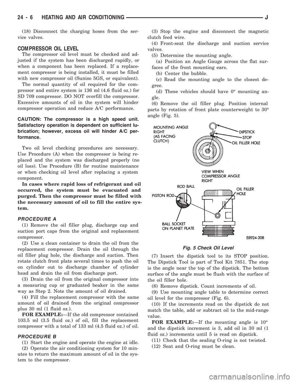
(6) Remove the oil filler plug. Position internal
parts by rotation of front plate counterweight to 30É
angle (Fig. 5).
(7) Insert the dipstick tool to its STOP position.
The Dipstick Tool is part of Tool Kit 7851. The stop
is the angle near the top of the dipstick. The bottom
surface of the angle must be flush with the surface of
the oil filler hole.
(8) Remove dipstick. Count increments of oil.
(9) Use mounting angle table to determine correct
oil level for the compressor (Fig. 6).
(10) If the increments read on the dipstick do not
match the table, add or subtract oil to the mid-range
value.
FOR EXAMPLE:ÐIf the mounting angle is 10É
and the dipstick increment is 3, add oil in 30 ml (1
fluid oz.) increments until 5 is read on dipstick.
(11) Check that the sealing O-ring is not twisted.
(12) Seat and O-ring must be clean.
Fig. 5 Check Oil Level
24 - 6 HEATING AND AIR CONDITIONINGJ
Page 1680 of 1784
COMPRESSOR OVERHAUL
INDEX
page page
Compressor............................. 17
Compressor Isolation...................... 17
Description............................. 17Magnetic Clutch......................... 18
Purging Compressor of Air................. 17
DESCRIPTION
The A/C system uses a Sanden compressor. This
compressor is a 7 piston design. Designated the SD-
709, the compressor is mounted on the front right
side of the engine and is driven by a serpentine belt.
System lubrication is provided by 135cc615cc (4.6
cu. in.60.5 cu. in.) of 500 viscosity refrigerant oil.
The clutch used on the compressor consists of 3 ba-
sic components: the pulley, front plate and the field
coil. The pulley and field coil are attached to the
front head of the compressor with tapered snap rings.
The hub is keyed to the compressor shaft and is re-
tained on the shaft with a self-locking nut. Special
service tools are required to remove and install the
clutch plate on the compressor shaft.
COMPRESSOR ISOLATION
It is not necessary to discharge the system for com-
pressor removal. The compressor can be isolated from
the remainder of the system and eliminate the need
for recharging when performing compressor service.
(1) Connect pressure gauge and manifold.
(2) Close both gauge hand valves.
(3) Mid-position both service valves.
WARNING: USE EXTREME CAUTION WHEN THE
ENGINE IS OPERATING. DO NOT STAND IN A DI-
RECT LINE WITH THE FAN. DO NOT PUT YOUR
HANDS NEAR THE PULLEYS, BELTS OR FAN. DO
NOT WEAR LOOSE CLOTHING.
(4) Start the engine and operate the air condition-
ing system.
(5) Turn the suction service valve slowly clockwise
toward the front seated position.
(6) When pressure drops to zero, stop the engine
and compressor and quickly finish front-seating the
suction service valve.
(7) Front-seat the discharge service valve.
(8) Loosen the oil level check plug slowly to re-
lease any internal pressure in the compressor.
The compressor is now isolated from the remainder
of the system.
The service valves can be removed from the com-
pressor.
PURGING COMPRESSOR OF AIR
The compressor must be purged of air whenever it
has been isolated for an oil level check or other ser-
vice procedures without discharging the entire sys-
tem.
(1) Cap the service gauge ports on both of the ser-
vice valves.
(2) Back-seat the suction service valve to allow the
system refrigerant to enter the compressor.
(3) Place the discharge service valve in the mid-po-
sition or cracked-position.
(4) Loosen the discharge service valve gauge port
cap to permit the refrigerant to force any air out of
the compressor.
(5) Back-seat the discharge service valve and
tighten the gauge port cap.
(6) The compressor is now ready for service.
COMPRESSOR
REMOVAL
(1) Isolate the compressor.
(2) Disconnect negative cable from battery.
(3) Disconnect the clutch lead wire.
(4) Remove the discharge and inlet (suction) ser-
vice valves from the compressor. Plug or tape all the
openings.
(5) Remove the serpentine drive belt (refer to
Group 7, Cooling System for the proper procedure).
(6) Remove the bolts and lift the compressor from
the mounting bracket (Figs. 1 and 2).
INSTALLATION
If a replacement compressor is being installed;
check the oil level. Add or subtract oil as neces-
sary and install the magnetic clutch on the com-
pressor.
(1) If the mounting bracket was removed, install
the bracket to the block. Tighten the mounting bolts
to 27 NIm (20 ft. lbs.) torque.
(2) Install the compressor on the mounting
bracket. Tighten the bolts to 27 NIm (20 ft. lbs.)
torque.
(3) Install the serpentine drive belt (refer to Group
7, Cooling System for the proper procedure).
(4) Tighten the serpentine drive belt to the speci-
fied tension.
²New belt tensionÐ800-900 N (180-200 lb-f).
JHEATING AND AIR CONDITIONING 24 - 17
Page 1710 of 1784
AIR CONDITIONING
CONTENTS
page page
AIR CONDITIONING EQUIPMENT........... 4
AIR CONDITIONING PERFORMANCE TESTS . . 5
GENERAL INFORMATION.................. 1
REFRIGERANT LEAK TESTING, DISCHARGING,
EVACUATING AND CHARGING............ 8REFRIGERANT OIL....................... 9
SERVICE PRECAUTIONS.................. 3
WARNINGS AND CAUTIONS FOR R134A
SYSTEM.............................. 3
GENERAL INFORMATION
A/C COMPONENTS
COMPRESSORÐThe SD-709 Compressor is used
on all models. The compressor compresses the low-
pressure refrigerant vapor from the evaporator into a
high pressure, high temperature vapor. The compres-
sor is serviced as an assembly only.
CLUTCH PULLEY AND COILÐThey are
mounted on the compressor and providing a way to
drive the compressor. The compressor clutch and coil
are the only serviced parts on the SD-709 compres-
sor. When the compressor is not in operation, the
pulley free wheels on the clutch hub bearing. When
the coil is energized the clutch plate is magnetically
engaged with the pulley and turns the compressor
shaft.
CONDENSERÐThe condenser is located in front
of the engine radiator. Its function is to cool the hot
high pressure refrigerant gas. This causes it to con-
dense into high pressure liquid refrigerant.
FILTER-DRIERÐThe drier is used to remove con-
taminates and traces of moisture from the refriger-
ant system.
SIGHT-GLASSÐThe sight glass is located on top
of the filter drier. It is used as a diagnostic tool to ob-
serve refrigerant flow.
LOW-PRESSURE HIGH-PRESSURE CUT-OFF
SWITCHÐThe switch is located on the filter drier
and is wired in series with compressor clutch. When
the pressure drops down to 193 kPa (28 psi) the
switch interrupts the power to the compressor clutch.
When the pressure increases above 3100 to 3375 kPa
(450 to 490 psi) the switch interrupts the power to
the compressor clutch.
HIGH PRESSURE RELIEF VALVEÐThe valve
is located on the filter drier. The valve is used to pre-
vent excessive pressure up build of 3445 to 4135
kPag (500 to 600 psi) and above. This will prevent
damage to the compressor and other system compo-
nents.EXPANSION VALVEÐThe expansion valve is lo-
cated in the engine compartment on XJ vehicles. On
YJ vehicles it is located behind the A/C housing. Its
function is to meter refrigerant into the evaporator in
accordance with cooling requirements.
EVAPORATOR COILÐThe coil is located in the
A/C housing. Its function is to remove heat and de-
humidify the air before it enters the vehicle.
FIN SENSING CYCLING CLUTCH SWITCHÐ
The switch is attached to the evaporator coil. This
switch prevents condensate water on the evaporator
coil from freezing. It does this by cycling the com-
pressor clutch on and off. This switch is used onXJ
only
THERMOSTATÐThe thermostat is located in the
evaporator housing. Its function is to cycle the com-
pressor clutch to control temperature. The thermo-
stat is used on theYJonly.
REFRIGERANT LINESÐThe lines are used to
carry the refrigerant between the various system
components.
SERVICE PORTSÐThe high pressure service
port is located on the discharge line near the com-
pressor. The low pressure service port is located on
the suction line near the compressor. The compressor
no longer uses service valves.
After servicing the refrigerant system, always in-
stall service port caps.
REFRIGERANT
The vehicles use a new type of refrigerant called
R-134a. It is a non-toxic, non-flammable, clear color-
less liquified gas.
R-134a refrigerant is not compatible with R-12 re-
frigerant in an air conditioning system. A small
amount of R-12 in a R-134a system will cause com-
pressor failure, refrigerant oil sludge or poor A/C per-
formance.
JAIR CONDITIONING1
Page 1712 of 1784
WARNINGS AND CAUTIONS FOR R134A SYSTEM
WARNING: AVOID BREATHING A/C REFRIGERANT
AND LUBRICANT VAPOR OR MIST. EXPOSURE MAY
IRRITATE EYES, NOSE AND/OR THROAT. WEAR
EYE PROTECTION WHEN SERVICING THE AIR
CONDITIONING REFRIGERANT SYSTEM. SERIOUS
EYE INJURY CAN RESULT FROM EYE CONTACT
WITH REFRIGERANT. IF EYE CONTACT IS MADE,
SEEK MEDICAL ATTENTION IMMEDIATELY.
WARNING: DO NOT EXPOSE REFRIGERANT TO
OPEN FLAME. POISONOUS GAS IS CREATED
WHEN REFRIGERANT IS BURNED. AN ELEC-
TRONIC LEAK DETECTOR IS RECOMMENDED.
WARNING: IF ACCIDENTAL SYSTEM DISCHARGE
OCCURS, VENTILATE THE WORK AREA BEFORE
RESUMING SERVICE. LARGE AMOUNTS OF RE-
FRIGERANT RELEASED IN A CLOSED WORK AREA
WILL DISPLACE THE OXYGEN AND CAUSE SUFFO-
CATION.
WARNING: THE EVAPORATION RATE OF R-134A
REFRIGERANT AT AVERAGE TEMPERATURE AND
ALTITUDE IS EXTREMELY HIGH. AS A RESULT,
ANYTHING THAT COMES IN CONTACT WITH THE
REFRIGERANT WILL FREEZE. ALWAYS PROTECT
SKIN OR DELICATE OBJECTS FROM DIRECT CON-
TACT WITH REFRIGERANT.WARNING: R-134A SERVICE EQUIPMENT OR VEHI-
CLE A/C SYSTEM SHOULD NOT BE PRESSURE
TESTED OR LEAK TESTED WITH COMPRESSED
AIR. SOME MIXTURES OF AIR AND R-134A HAVE
BEEN SHOWN TO BE COMBUSTIBLE AT ELEVATED
PRESSURES. THESE MIXTURES ARE POTENTIALLY
DANGEROUS AND MAY RESULT IN FIRE OR EX-
PLOSION CAUSING INJURY OR PROPERTY DAM-
AGE.
CAUTION: Liquid refrigerant is corrosive to metal
surfaces. Follow the operating instructions supplied
with equipment being used.
CAUTION: Never add R-12 to a system designed to
use R-134a. Damage to the system will result.
CAUTION: R-12 compressor oil can not be mixed
with the R-134a compressor oil. They ARE NOT
compatible.
CAUTION: DO NOT use R-12 equipment or parts on
the R-134a system. Damage to the system will re-
sult.
SERVICE PRECAUTIONS
Never open or loosen a connection before discharg-
ing the system refrigerant.
The A/C system must always be evacuated before
charging.
DO NOT open a refrigerant system or uncap a re-
placement component unless it is as close as possible
to room temperature. This will prevent condensation
from forming inside of a component which is cooler
than the surrounding air.
Before disconnecting a component from the system,
clean the outside of the fittings thoroughly.
Immediately after disconnecting a component from
the system, seal the open fittings with a cap or plug.
Before connecting an open fitting always insall a
new seal/gasket. Coat the fitting and seal with clean
refrigerant oil before connecting.
DO NOT remove the sealing caps from a replace-
ment component until ready to install.When installing a refrigerant line avoid sharp
bends. Position the line away from the exhaust or
any sharp edges which may chafe the line.
Tighten fittings only to the specified torque. The
aluminum fittings used in the A/C system will not
tolerate over tightening.
When disconnecting a fitting use a wrench on both
halves of the fitting. This will prevent twisting of the
refrigerant lines or tubes.
Refrigerant oil will absorb moisture from the atmo-
sphere if left uncapped. DO NOT open an oil con-
tainer until ready to use and install the cap
immediately after using. Store the oil only in a clean
moisture-free container.
Keep service tools and the work area clean. Con-
tamination of A/C system through careless work hab-
its must be avoided.
JAIR CONDITIONING3
Page 1713 of 1784
AIR CONDITIONING EQUIPMENT
WARNING: EYE PROTECTION MUST BE USED
WHEN SERVICING AN AIR CONDITIONING REFRIG-
ERANT SYSTEM. TURN OFF (ROTATE CLOCKWISE)
ALL VALVES ON THE EQUIPMENT BEING USED
BEFORE PROCEEDING WITH THIS OPERATION.
PERSONNEL INJURY CAN RESULT.
When servicing an air conditioning system, a
R-134a Charging Station and a Recovery/Recycling
Station is required. These devices must meet SAE
standard J2210. Refer to the operating instructions
provided with the equipment for proper operation.
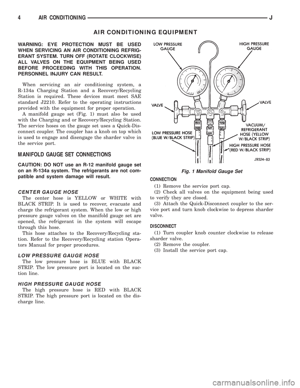
A manifold gauge set (Fig. 1) must also be used
with the Charging and or Recovery/Recycling Station.
The service hoses on the gauge set uses a Quick-Dis-
connect coupler. The coupler has a knob on top which
is used to engage and disengage the sharder valve in
the service port.
MANIFOLD GAUGE SET CONNECTIONS
CAUTION: DO NOT use an R-12 manifold gauge set
on an R-134a system. The refrigerants are not com-
patible and system damage will result.
CENTER GAUGE HOSE
The center hose is YELLOW or WHITE with
BLACK STRIP. It is used to recover, evacuate and
charge the refrigerant system. When the low or high
pressure gauge valves on the manifold gauge set are
opened, the refrigerant in the system will escape
through this hose.
This hose attaches to the Recovery/Recycling sta-
tion. Refer to the Recovery/Recycling station Opera-
tors Manual for proper procedures.
LOW PRESSURE GAUGE HOSE
The low pressure hose is BLUE with BLACK
STRIP. The low pressure port is located on the suc-
tion line.
HIGH PRESSURE GAUGE HOSE
The high pressure hose is RED with BLACK
STRIP. The high pressure port is located on the dis-
charge line.CONNECTION
(1) Remove the service port cap.
(2) Check all valves on the equipment being used
to verify they are closed.
(3) Attach the Quick-Disconnect coupler to the ser-
vice port and turn knob clockwise to depress sharder
valve.
DISCONNECT
(1) Turn coupler knob counter clockwise to release
sharder valve.
(2) Remove the coupler.
(3) Install the service port cap.
Fig. 1 Manifold Gauge Set
4 AIR CONDITIONINGJ
Page 1717 of 1784
REFRIGERANT LEAK TESTING, DISCHARGING, EVACUATING AND CHARGING
LEAK TESTING REFRIGERANT
WARNING: REVIEW WARNINGS AND CAUTIONS IN
GENERAL INFORMATION SECTION OF THIS
GROUP BEFORE LEAK TESTING.
If A/C system is not cooling properly, determine if
system is fully charged. Refer to Refrigerant System
Diagnosis Chart. If the system is empty evacuate the
A/C system and charge system with 0.283 kPa (0.6
lbs. or 10 oz.) R-134a refrigerant. Refer to Charging
Refrigerant System for instructions. To detect a leak
in the system, perform the following procedures.
(1) Position the vehicle in a wind free work area.
This will aid in detecting small leaks.
(2) Bring A/C system up to operating temperature
and pressure. This is done by allowing the engine to
run with the A/C on for 5 to 7 minutes.
(3) Open hood 5 minutes prior to leak test. This
will dissipate any accumulated refrigerant in the en-
gine compartment.
(4) With the engine not running, use an R-134a
Electronic Leak Detector and search for leaks. Move
probe slowly along the bottom side of lines and fit-
tings, because R-134a is heavier than air. Fittings,
lines, or components that appear to be oily usually
indicates a refrigerant leak.
(5) To inspect the evaporator core for leaks. Set the
blower at low speed and the selector in PANEL and
RECIRC mode check for leaks at CENTER panel ou-
lets.
DISCHARGING REFRIGERANT SYSTEM
WARNING: REVIEW WARNINGS AND CAUTIONS IN
GENERAL INFORMATION SECTION OF THIS
GROUP BEFORE DISCHARGING SYSTEM.
R-134a refrigrant is a hydrofluorocarbon (HFC)
that does not contain chlorine. R-134a refrigerant Re-
covery/Recycling Station that meets SAE standard
J2210 must be used to discharge the refrigerant sys-
tem. Refer to the operating instructions provided
with the equipment for proper operation.
EVACUATING REFRIGERANT SYSTEM
WARNING: REVIEW WARNINGS AND CAUTIONS IN
GENERAL INFORMATION SECTION OF THIS
GROUP BEFORE EVACUATING SYSTEM.If the A/C system has been open to the atmosphere,
it must be evacuated before the system can be
charged. Moisture and air mixed with refrigerant will
raise the compressor head pressure above acceptable
operating levels. This will reduce the performance of
the air conditioner and damage the compressor. Mois-
ture will boil at near room temperature when ex-
posed to vacuum. To evacuate the refrigerant system
use following procedure:
(1) Connect a suitable charging station and mani-
fold gauge set to the vehicle.
(2) Open the low and high side valves and start
vacuum pump. When suction gauge reads 88 kPag
(26 in. Hg) vacuum or greater, close all valves and
turn off vacuum pump. If system fails to reach spec-
ified vacuum, the system has a leak that must be
corrected. If system maintains the specified vacuum
for 30 minutes, start the vacuum pump. Then open
the suction and discharge valves and evacuate an ad-
ditional 10 minutes.
(3) Close all valves. Turn off and disconnect the
vacuum pump.
The system is now ready to be charged with refrig-
erant.
CHARGING REFRIGERANT SYSTEM
WARNING: REVIEW WARNINGS AND CAUTIONS IN
GENERAL INFORMATION SECTION OF THIS
GROUP BEFORE CHARGING SYSTEM.
After the system has been tested for leaks and
evacuated, a refrigerant charge can be injected into
the system. Refer to refrigerant capacities for proper
amount of refrigerant charge.
The most accurate method of charging is to com-
pletely evacuate the system. Then charge the system
using a Recovery/Recycling Station approved for
R-134a refrigerant. Refer to the operating instruc-
tions provided with the equipment for proper opera-
tion.
CAUTION: Do not over charge refrigerant system.
This will cause excessive compressor head pres-
sure and can cause noise and system failure.
REFRIGERANT CHARGE CAPACITY
The R-134a system charge capacity is 0.9 kPag (32
oz.) for XJ and YJ vehicles.
8 AIR CONDITIONINGJ