1994 JEEP CHEROKEE charging
[x] Cancel search: chargingPage 275 of 1784
BATTERY TEST PROCEDURES
INDEX
page page
Battery Charging.......................... 5
Battery Diagnostics Chart................... 7
Battery Load Test......................... 4
Battery Open Circuit Voltage Test............. 3Battery Testing General Information........... 3
General Information........................ 2
Hydrometer Test.......................... 3
Specifications............................ 8
GENERAL INFORMATION
The battery stores, stabilizes, and produces electri-
cal current. A battery must be able to accept a
charge and produce high-amperage current output
over an extended period. A chemical reaction occurs
between the sulfuric acid solution (electrolyte) and
the lead +/þ plates in each cell of the battery. As
the battery discharges, the plates collect the acid
from the electrolyte. When the charging system
charges the battery, water is converted to sulfuric
acid in the battery. The amount of acid (specific
gravity) in the electrolyte can be measured with a
hydrometer. The battery is vented to release gases
that are created when the battery is being charged.
The battery top,posts, and terminals should be cleaned when other
underhood maintenance is performed.
WARNING: DO NOT ATTEMPT TO ASSIST BOOST,
CHARGE, OR TEST BATTERY WHEN ELECTRO-
LYTE LEVEL IS BELOW THE TOP OF THE PLATES.
PERSONAL INJURY MAY OCCUR.
When the electrolyte level is below the top of the
plates distilled water should be added. The battery
must be completely charged. The top, posts, and ter-
minals should be properly cleaned before diagnostic
procedures are performed. See Group 8B - Battery/
Starter/Generator Service, for additional information.
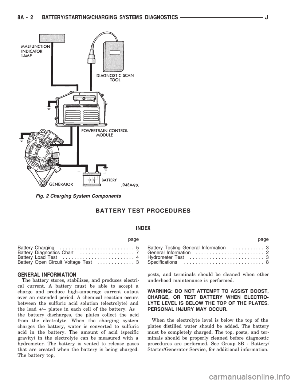
Fig. 2 Charging System Components
8A - 2 BATTERY/STARTING/CHARGING SYSTEMS DIAGNOSTICSJ
Page 276 of 1784
BATTERY TESTING GENERAL INFORMATION
Before testing a battery, clean the top of the
battery case, posts and cable terminals.
Specific gravity is a ratio of the density of the elec-
trolyte and the density of pure water. The electrolyte
is composed of sulfuric acid and water. Acid makes
up approximately 35% of the electrolyte by weight,
or 24% by volume.
The condition of a battery may be determined from
the results of 2 tests:
²hydrometer test
²ability to supply current (battery load test)
Perform the hydrometer test first. If the specific
gravity is less than 1.235, (with battery at room tem-
perature) the battery must be charged before pro-
ceeding with further testing. A battery that will not
accept a charge is defective and further testing is not
necessary.
Completely discharged batteries may take sev-
eral hours to accept a charge. See Charging
Completely Discharged Battery.
A battery that has been fully charged but does not
pass the battery load test is defective.
A battery is fully charged when:
²all cells are gassing freely during charging
²3 corrected specific gravity tests, taken at 1-hour
intervals, indicate no increase in specific gravity.
ABNORMAL BATTERY DISCHARGING
(1) Corroded battery posts and terminals.
(2) Loose or worn generator drive belt.
(3) Electrical loads that exceed the output of the
charging system due to equipment or accessories in-
stalled after delivery.
(4) Slow driving speeds (heavy traffic conditions)
or prolonged idling with high-amperage draw sys-
tems in use.
(5) Defective circuit or component causing excess
IOD. Refer to Ignition Off Draw Diagnosis in this
group.
(6) Defective charging system.
(7) Defective battery.
HYDROMETER TEST
Before performing a hydrometer test, remove
battery caps and check electrolyte level. Add
distilled water as required.
Before testing, visually inspect battery for any
damage (cracked case or cover, loose post, etc.) that
would cause the battery to be defective. To use the
hydrometer correctly, hold it with the top surface of
the electrolyte at eye level. Refer to manufacturers
instructions for correct use of hydrometer.
Remove only enough electrolyte from the battery to
keep the float off the bottom of the hydrometer bar-
rel with pressure on the bulb released. Exercise care
when inserting the tip of the hydrometer into a cellto avoid damage to the separators. Damaged separa-
tors can cause premature battery failure.
Hydrometer floats are generally calibrated to indi-
cate the specific gravity correctly only at one fixed
temperature, 80ÉF (26.6ÉC). When testing the specific
gravity at any other temperature, a correction factor
is required.
The correction factor is approximately a specific
gravity value of 0.004, referred to as 4 points of spe-
cific gravity. For each 10ÉF above 80ÉF (5.5ÉC above
26.6ÉC), add 4 points. For each 10ÉF below 80ÉF
(5.5ÉC below 26.6ÉC), subtract 4 points. Always cor-
rect the specific gravity for temperature variation.
Test the specific gravity of the electrolyte in each
battery cell.
Example: A battery is tested at 10ÉF (-12.2ÉC) and
has a specific gravity of 1.240. Determine the actual
specific gravity as follows:
²Determine the number of degrees above or below
80ÉF:
80ÉF - 10ÉF = 70ÉF
²Divide the result above by 10:
70ÉF/10 = 7
²Multiply the result from the previous step by the
temperature correction factor (0.004):
7 x 0.004 = 0.028
²The temperature at testing was below 80ÉF, there-
fore the temperature correction is subtracted:
1.240 - 0.028 = 1.212
²The corrected specific gravity is 1.212.
The fully charged battery should have a tempera-
ture corrected specific gravity of 1.260 to 1.290.
If the specific gravity of all cells is above 1.235,
and cell variation is more than 50 points (0.050), it is
an indication that the battery is unserviceable.
If the specific gravity of one or more cells is less
than 1.235, charge the battery at a rate of approxi-
mately 5 amperes. Continue charging until 3 consec-
utive specific gravity tests, taken at 1 hour intervals,
are constant.
If the cell specific gravity variation is more than 50
points (0.050) after the charge period, replace the
battery.
When the specific gravity of all cells is above 1.235
and variation between cells is less than 50 points
(0.050), the battery may be tested under heavy load.
BATTERY OPEN CIRCUIT VOLTAGE TEST
A battery voltage (no load) test will show state of
charge of a battery that will pass the Battery Load
Test described in this section.Before proceeding
with this test or Battery Load Test, completely
charge battery as described in Battery Charging
in this section.
If a battery has a no load voltage reading of 12.4
volts or greater and will not endure a load test, it is
defective and should be replaced. Refer to Group 8B -
JBATTERY/STARTING/CHARGING SYSTEMS DIAGNOSTICS 8A - 3
Page 277 of 1784
Battery/Starter/Generator Service for instructions. To
test battery no load voltage, perform the following
operation:
(1) Before measuring open circuit voltage, the sur-
face charge must be removed from plates. Turn head-
lamps on for 15 seconds then allow up to 5 minutes
for voltage to stabilize.
(2) Remove both battery cables, negative first.
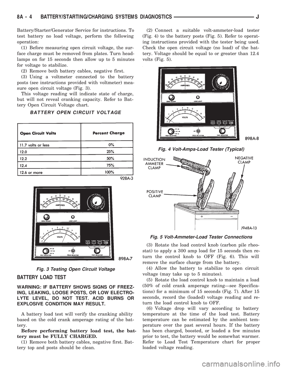
(3) Using a voltmeter connected to the battery
posts (see instructions provided with voltmeter) mea-
sure open circuit voltage (Fig. 3).
This voltage reading will indicate state of charge,
but will not reveal cranking capacity. Refer to Bat-
tery Open Circuit Voltage chart.
BATTERY LOAD TEST
WARNING: IF BATTERY SHOWS SIGNS OF FREEZ-
ING, LEAKING, LOOSE POSTS, OR LOW ELECTRO-
LYTE LEVEL, DO NOT TEST. ACID BURNS OR
EXPLOSIVE CONDITION MAY RESULT.
A battery load test will verify the cranking ability
based on the cold crank amperage rating of the bat-
tery.
Before performing battery load test, the bat-
tery must be FULLY CHARGED.
(1) Remove both battery cables, negative first. Bat-
tery top and posts should be clean.(2) Connect a suitable volt-ammeter-load tester
(Fig. 4) to the battery posts (Fig. 5). Refer to operat-
ing instructions provided with the tester being used.
Check the open circuit voltage (no load) of the bat-
tery. Voltage should be equal to or greater than 12.4
volts (Fig. 5).
(3) Rotate the load control knob (carbon pile rheo-
stat) to apply a 300 amp load for 15 seconds then re-
turn the control knob to OFF (Fig. 6). This will
remove the surface charge from the battery.
(4) Allow the battery to stabilize to open circuit
voltage (may take up to 5 minutes).
(5) Rotate the load control knob to maintain a load
(50% of cold crank amperage ratingÐsee Specifica-
tions) for a minimum of 15 seconds (Fig. 7). After 15
seconds, record the (loaded) voltage reading and re-
turn the load control knob to OFF.
(6) Voltage drop will vary according to battery
temperature at the time of the load test. Battery
temperature can be estimated by the ambient tem-
perature over the past several hours. If the battery
has been charged, boosted, or loaded a few minutes
prior to test, the battery would be somewhat warmer.
Refer to Load Test Temperature chart for proper
loaded voltage reading.
Fig. 4 Volt-Amps-Load Tester (Typical)
Fig. 5 Volt-Ammeter-Load Tester Connections
BATTERY OPEN CIRCUIT VOLTAGE
Fig. 3 Testing Open Circuit Voltage
8A - 4 BATTERY/STARTING/CHARGING SYSTEMS DIAGNOSTICSJ
Page 278 of 1784
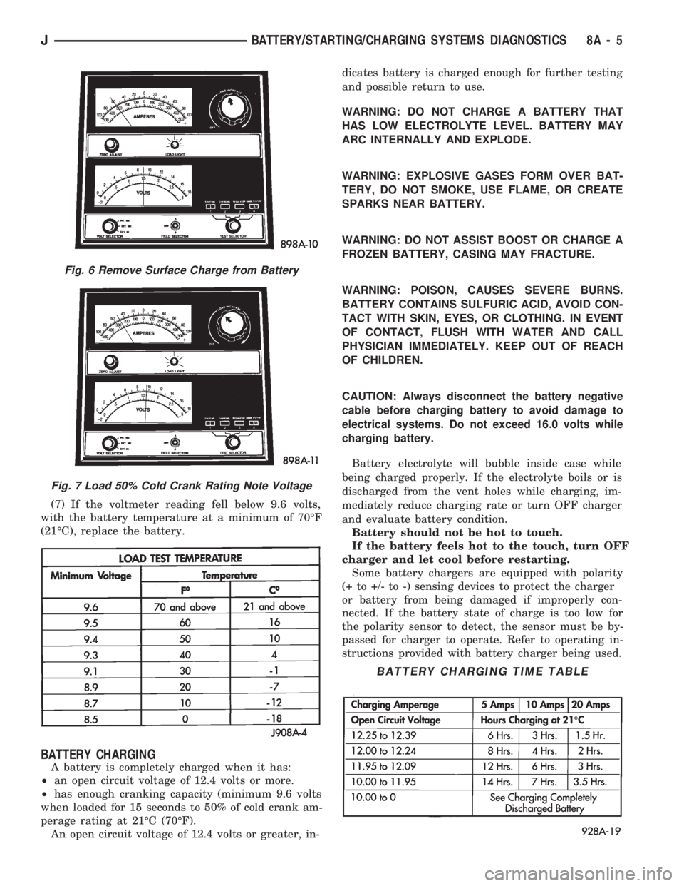
(7) If the voltmeter reading fell below 9.6 volts,
with the battery temperature at a minimum of 70ÉF
(21ÉC), replace the battery.
BATTERY CHARGING
A battery is completely charged when it has:
²an open circuit voltage of 12.4 volts or more.
²has enough cranking capacity (minimum 9.6 volts
when loaded for 15 seconds to 50% of cold crank am-
perage rating at 21ÉC (70ÉF).
An open circuit voltage of 12.4 volts or greater, in-dicates battery is charged enough for further testing
and possible return to use.
WARNING: DO NOT CHARGE A BATTERY THAT
HAS LOW ELECTROLYTE LEVEL. BATTERY MAY
ARC INTERNALLY AND EXPLODE.
WARNING: EXPLOSIVE GASES FORM OVER BAT-
TERY, DO NOT SMOKE, USE FLAME, OR CREATE
SPARKS NEAR BATTERY.
WARNING: DO NOT ASSIST BOOST OR CHARGE A
FROZEN BATTERY, CASING MAY FRACTURE.
WARNING: POISON, CAUSES SEVERE BURNS.
BATTERY CONTAINS SULFURIC ACID, AVOID CON-
TACT WITH SKIN, EYES, OR CLOTHING. IN EVENT
OF CONTACT, FLUSH WITH WATER AND CALL
PHYSICIAN IMMEDIATELY. KEEP OUT OF REACH
OF CHILDREN.
CAUTION: Always disconnect the battery negative
cable before charging battery to avoid damage to
electrical systems. Do not exceed 16.0 volts while
charging battery.
Battery electrolyte will bubble inside case while
being charged properly. If the electrolyte boils or is
discharged from the vent holes while charging, im-
mediately reduce charging rate or turn OFF charger
and evaluate battery condition.
Battery should not be hot to touch.
If the battery feels hot to the touch, turn OFF
charger and let cool before restarting.
Some battery chargers are equipped with polarity
(+ to +/- to -) sensing devices to protect the charger
or battery from being damaged if improperly con-
nected. If the battery state of charge is too low for
the polarity sensor to detect, the sensor must be by-
passed for charger to operate. Refer to operating in-
structions provided with battery charger being used.
Fig. 6 Remove Surface Charge from Battery
Fig. 7 Load 50% Cold Crank Rating Note Voltage
BATTERY CHARGING TIME TABLE
JBATTERY/STARTING/CHARGING SYSTEMS DIAGNOSTICS 8A - 5
Page 279 of 1784
After the battery has been charged to 12.4 volts or
greater, perform a load test to determine cranking
capacity. If the battery will endure a load test, re-
turn the battery to use. If battery will not endure a
load test, it must be replaced. Clean and inspect bat-
tery holddowns, tray, terminals, posts, and top before
completing service, see Group 8B - Battery/Starter/
Generator Service.
CHARGING TIME REQUIRED
The time required to charge a battery will vary de-
pending upon the following factors:
(1)Size of BatteryÐA completely discharged
large, heavy-duty battery requires more than twice
the recharging time as a completely discharged small
capacity battery.
WARNING: NEVER EXCEED 20 AMPS WHEN
CHARGING A COLD (-1ÉC/30ÉF) BATTERY, PER-
SONAL INJURY MAY RESULT.
(2)TemperatureÐA longer time will be needed
to charge a battery at -18ÉC (0ÉF) than at 27ÉC
(80ÉF). When a fast charger is connected to a cold
battery, current accepted by battery will be very low
at first. Then, in time, the battery will accept a
higher rate as battery warms.
(3)Charger CapacityÐA charger, that supplies
only 5 amperes, will require a longer charging time
than a charger that supplies 20 amperes or more.
(4)State Of ChargeÐA completely discharged
battery requires more charging time than a partially
charged battery. Electrolyte is nearly pure water in a
completely discharged battery. At first the charging
current amperage will be low. As the battery charges
the specific gravity of the electrolyte will rise slowly.
CHARGING COMPLETELY DISCHARGED
BATTERY
The following procedure should be used to recharge
a completely discharged battery. Unless procedure is
properly followed, a good battery may be needlessly
replaced.
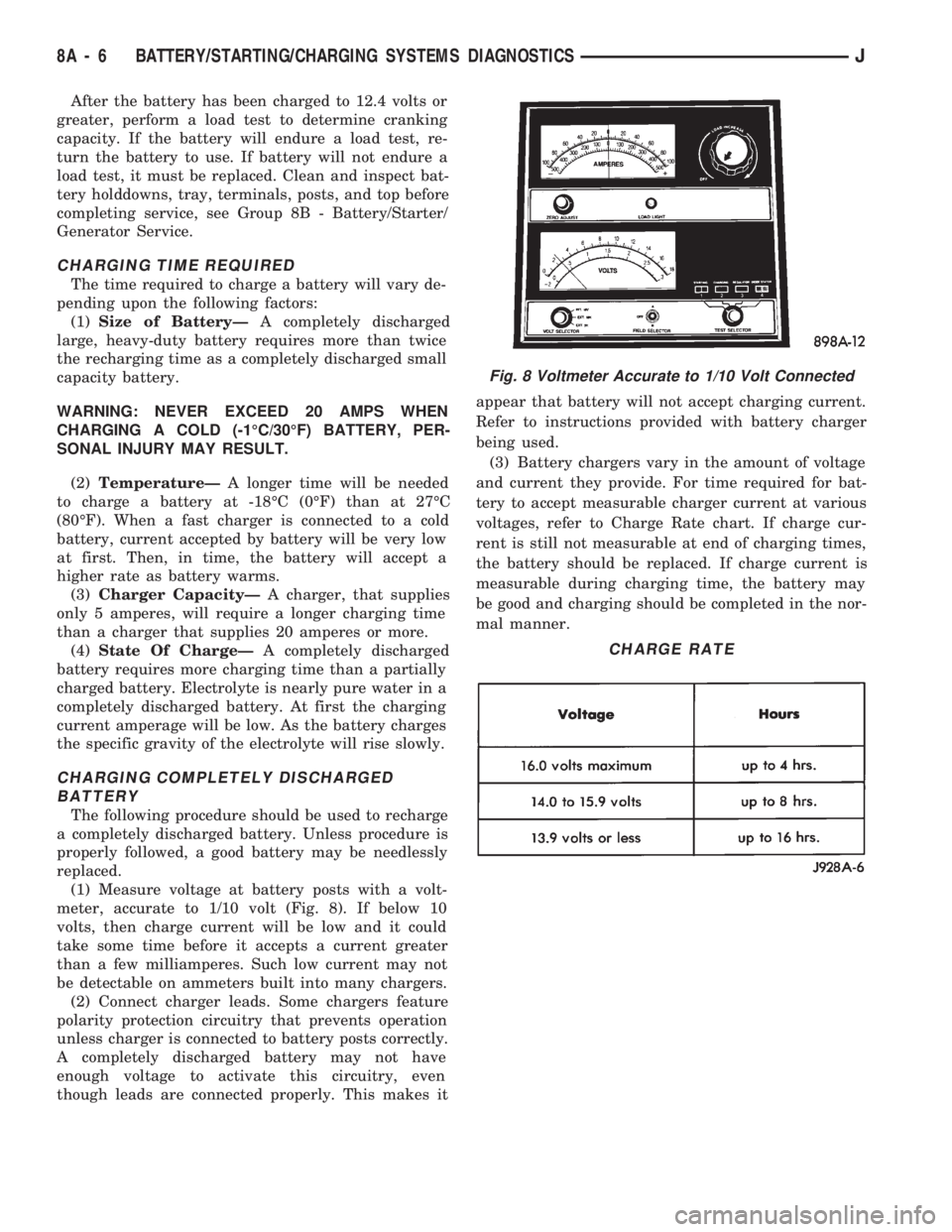
(1) Measure voltage at battery posts with a volt-
meter, accurate to 1/10 volt (Fig. 8). If below 10
volts, then charge current will be low and it could
take some time before it accepts a current greater
than a few milliamperes. Such low current may not
be detectable on ammeters built into many chargers.
(2) Connect charger leads. Some chargers feature
polarity protection circuitry that prevents operation
unless charger is connected to battery posts correctly.
A completely discharged battery may not have
enough voltage to activate this circuitry, even
though leads are connected properly. This makes itappear that battery will not accept charging current.
Refer to instructions provided with battery charger
being used.
(3) Battery chargers vary in the amount of voltage
and current they provide. For time required for bat-
tery to accept measurable charger current at various
voltages, refer to Charge Rate chart. If charge cur-
rent is still not measurable at end of charging times,
the battery should be replaced. If charge current is
measurable during charging time, the battery may
be good and charging should be completed in the nor-
mal manner.
Fig. 8 Voltmeter Accurate to 1/10 Volt Connected
CHARGE RATE
8A - 6 BATTERY/STARTING/CHARGING SYSTEMS DIAGNOSTICSJ
Page 280 of 1784
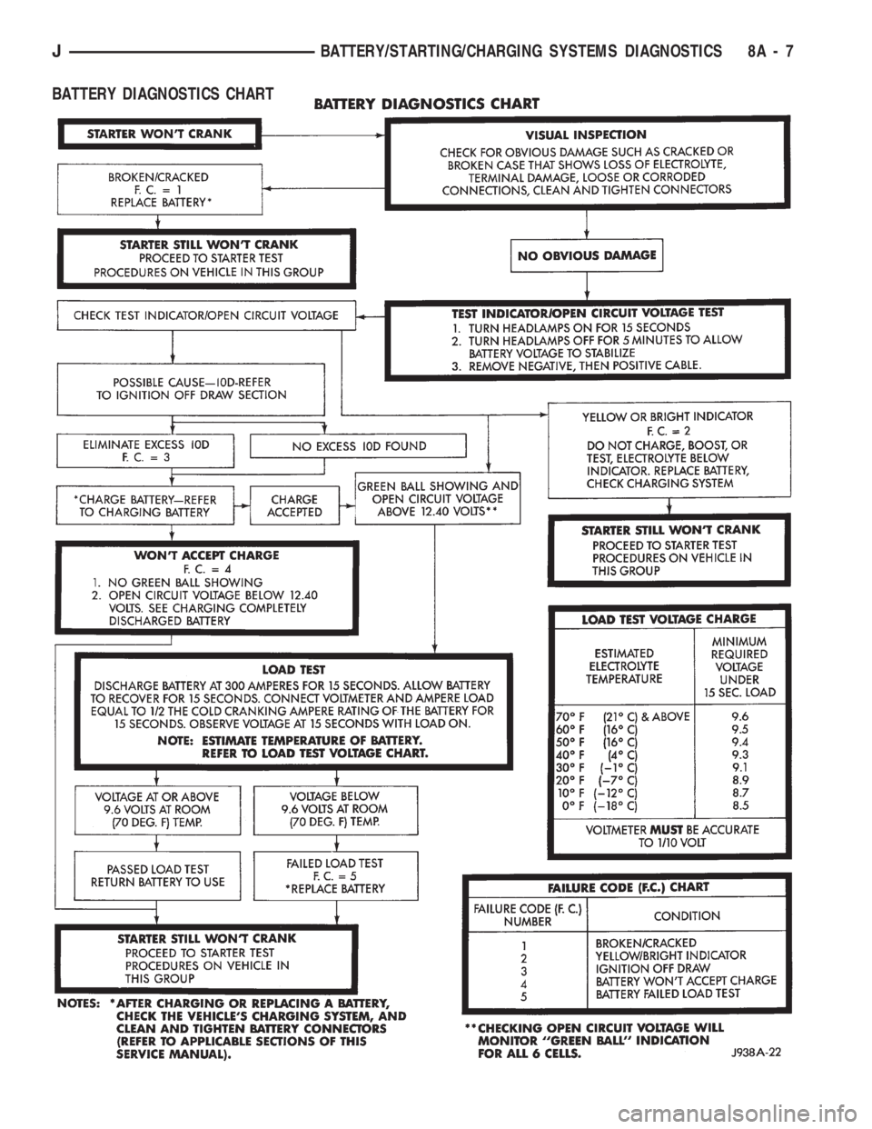
BATTERY DIAGNOSTICS CHART
JBATTERY/STARTING/CHARGING SYSTEMS DIAGNOSTICS 8A - 7
Page 281 of 1784
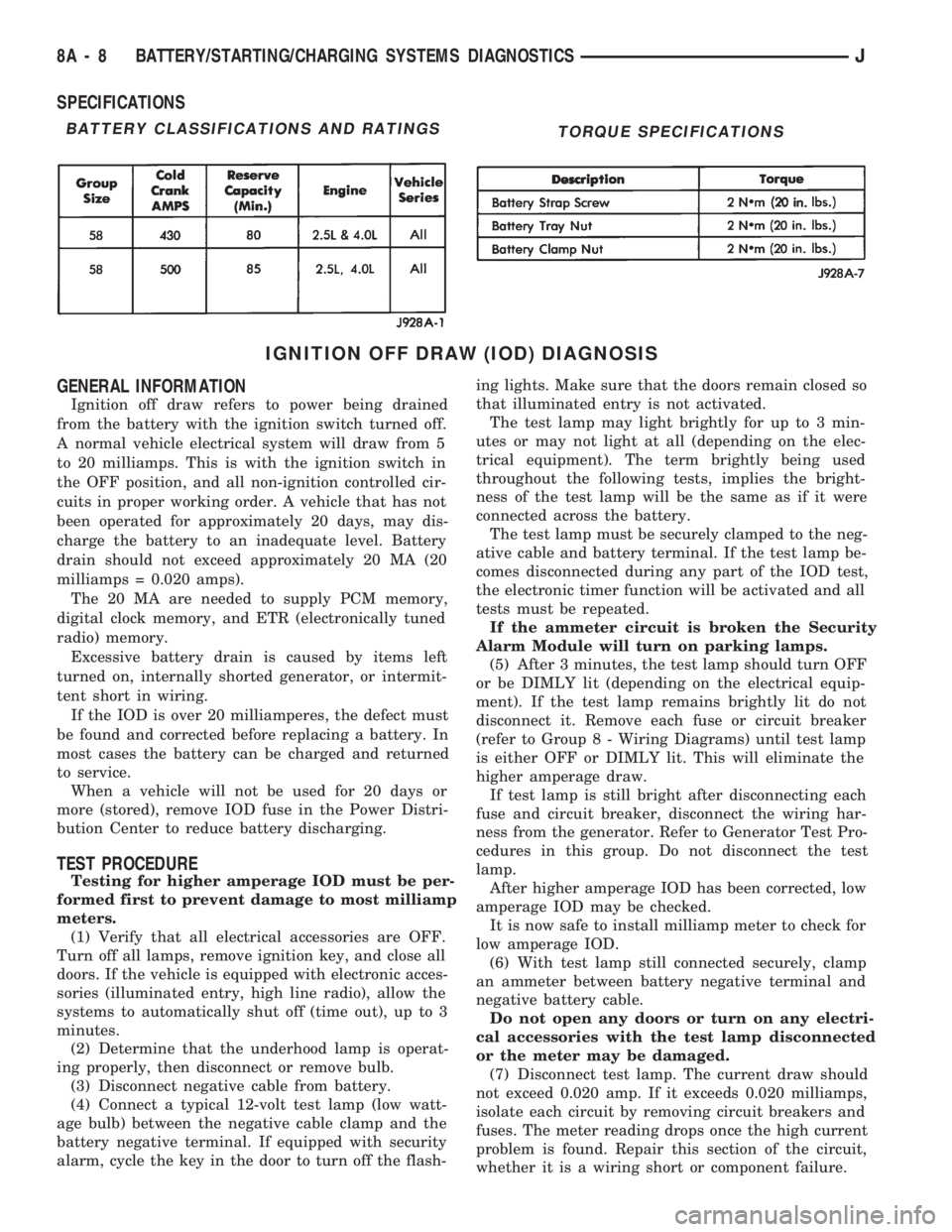
SPECIFICATIONS
IGNITION OFF DRAW (IOD) DIAGNOSIS
GENERAL INFORMATION
Ignition off draw refers to power being drained
from the battery with the ignition switch turned off.
A normal vehicle electrical system will draw from 5
to 20 milliamps. This is with the ignition switch in
the OFF position, and all non-ignition controlled cir-
cuits in proper working order. A vehicle that has not
been operated for approximately 20 days, may dis-
charge the battery to an inadequate level. Battery
drain should not exceed approximately 20 MA (20
milliamps = 0.020 amps).
The 20 MA are needed to supply PCM memory,
digital clock memory, and ETR (electronically tuned
radio) memory.
Excessive battery drain is caused by items left
turned on, internally shorted generator, or intermit-
tent short in wiring.
If the IOD is over 20 milliamperes, the defect must
be found and corrected before replacing a battery. In
most cases the battery can be charged and returned
to service.
When a vehicle will not be used for 20 days or
more (stored), remove IOD fuse in the Power Distri-
bution Center to reduce battery discharging.
TEST PROCEDURE
Testing for higher amperage IOD must be per-
formed first to prevent damage to most milliamp
meters.
(1) Verify that all electrical accessories are OFF.
Turn off all lamps, remove ignition key, and close all
doors. If the vehicle is equipped with electronic acces-
sories (illuminated entry, high line radio), allow the
systems to automatically shut off (time out), up to 3
minutes.
(2) Determine that the underhood lamp is operat-
ing properly, then disconnect or remove bulb.
(3) Disconnect negative cable from battery.
(4) Connect a typical 12-volt test lamp (low watt-
age bulb) between the negative cable clamp and the
battery negative terminal. If equipped with security
alarm, cycle the key in the door to turn off the flash-ing lights. Make sure that the doors remain closed so
that illuminated entry is not activated.
The test lamp may light brightly for up to 3 min-
utes or may not light at all (depending on the elec-
trical equipment). The term brightly being used
throughout the following tests, implies the bright-
ness of the test lamp will be the same as if it were
connected across the battery.
The test lamp must be securely clamped to the neg-
ative cable and battery terminal. If the test lamp be-
comes disconnected during any part of the IOD test,
the electronic timer function will be activated and all
tests must be repeated.
If the ammeter circuit is broken the Security
Alarm Module will turn on parking lamps.
(5) After 3 minutes, the test lamp should turn OFF
or be DIMLY lit (depending on the electrical equip-
ment). If the test lamp remains brightly lit do not
disconnect it. Remove each fuse or circuit breaker
(refer to Group 8 - Wiring Diagrams) until test lamp
is either OFF or DIMLY lit. This will eliminate the
higher amperage draw.
If test lamp is still bright after disconnecting each
fuse and circuit breaker, disconnect the wiring har-
ness from the generator. Refer to Generator Test Pro-
cedures in this group. Do not disconnect the test
lamp.
After higher amperage IOD has been corrected, low
amperage IOD may be checked.
It is now safe to install milliamp meter to check for
low amperage IOD.
(6) With test lamp still connected securely, clamp
an ammeter between battery negative terminal and
negative battery cable.
Do not open any doors or turn on any electri-
cal accessories with the test lamp disconnected
or the meter may be damaged.
(7) Disconnect test lamp. The current draw should
not exceed 0.020 amp. If it exceeds 0.020 milliamps,
isolate each circuit by removing circuit breakers and
fuses. The meter reading drops once the high current
problem is found. Repair this section of the circuit,
whether it is a wiring short or component failure.
BATTERY CLASSIFICATIONS AND RATINGSTORQUE SPECIFICATIONS
8A - 8 BATTERY/STARTING/CHARGING SYSTEMS DIAGNOSTICSJ
Page 282 of 1784
ENGINE STARTER MOTOR TEST PROCEDURES ON VEHICLE
INDEX
page page
2.5L Starter Motor Noise Diagnosis........... 13
General Information........................ 9
Starter Control Circuit Tests................ 11
Starter Feed Circuit Tests - (Voltage Drop Method).9
Starter System Diagnostic Inspections.......... 9
Starting System Cold Cranking Test........... 9
GENERAL INFORMATION
The starting system consists of an:
²ignition switch
²starter relay
²park/neutral position switch (automatic transmis-
sion)
²wiring harness
²battery
²starter motor with an integral solenoid.
These components form 2 separate circuits. A high
amperage circuit that feeds the starter motor up to
300+ amps, and a control circuit that operates on
less than 20 amps.
STARTER SYSTEM DIAGNOSTIC INSPECTIONS
Before removing any unit from the starter motor
system for repair, perform the following inspections:
BATTERY INSPECTION
To determine condition of the battery, perform the
testing procedure outlined in Battery Test Proce-
dures.
WIRING INSPECTION
Inspect wiring for damage. Inspect all connections
at the starter motor solenoid, park/neutral position
switch (if equipped), back-up lamp switch connector,
ignition switch, starter relay, and battery (including
all ground connections). Clean and tighten all con-
nections as required.
SOLENOID, RELAY AND IGNITION SWITCH
INSPECTION
Inspect the solenoid, relay and switch to determine
their condition. Also, if equipped with automatic
transmission, inspect condition of the park/neutral
position switch. Testing information can be found in
the following pages.
STARTING SYSTEM COLD CRANKING TEST
(1) Battery must first pass load and voltage drop
tests and be fully charged before proceeding. Refer to
Battery Test Procedures.(2) Connect a suitable volt-ampere tester to the
battery terminals (Fig. 1). Refer to the operating in-
structions provided with the tester being used.
(3) Fully engage parking brake, place manual
transmission in NEUTRAL, automatic transmission
in PARK.
(4) Verify that all lamps and accessories are OFF.
(5) Remove coil secondary cable from distributor
and connect to ground.
(6) Rotate and hold the ignition switch in the
START position. Note cranking voltage and amper-
age.
(a) If voltage reads above 9.6 volts and amperage
draw reads above specifications, go to Starter Feed
Circuit Tests.
(b) If voltage reads 12.5 volts or greater and am-
perage reads below specifications, go to Starter
Control Circuit Tests.
A cold engine will increase starter motor cur-
rent and reduce battery voltage.
STARTER FEED CIRCUIT TESTS - (VOLTAGE DROP
METHOD)
The voltage drop tests will determine if there is ex-
cessive resistance in the high current circuit. When
performing these tests, it is important that the volt-
meter be connected to the terminals that the cables
are connected to, instead of to the cables themselves.
For example, when testing between the battery and
solenoid, touch the voltmeter test probes to the bat-
tery post and the solenoid threaded stud. The follow-
ing operation will require a voltmeter, accurate to
1/10 of a volt.
Before performing the tests, assure the following
procedures are accomplished:
²remove coil secondary cable from distributor and
connect to ground
²transmission in NEUTRAL (manual transmission)
or PARK (automatic transmission)
²parking brake applied
²battery is fully charged (refer to Battery Test Pro-
cedures).
JBATTERY/STARTING/CHARGING SYSTEMS DIAGNOSTICS 8A - 9