1994 JEEP CHEROKEE charging
[x] Cancel search: chargingPage 291 of 1784
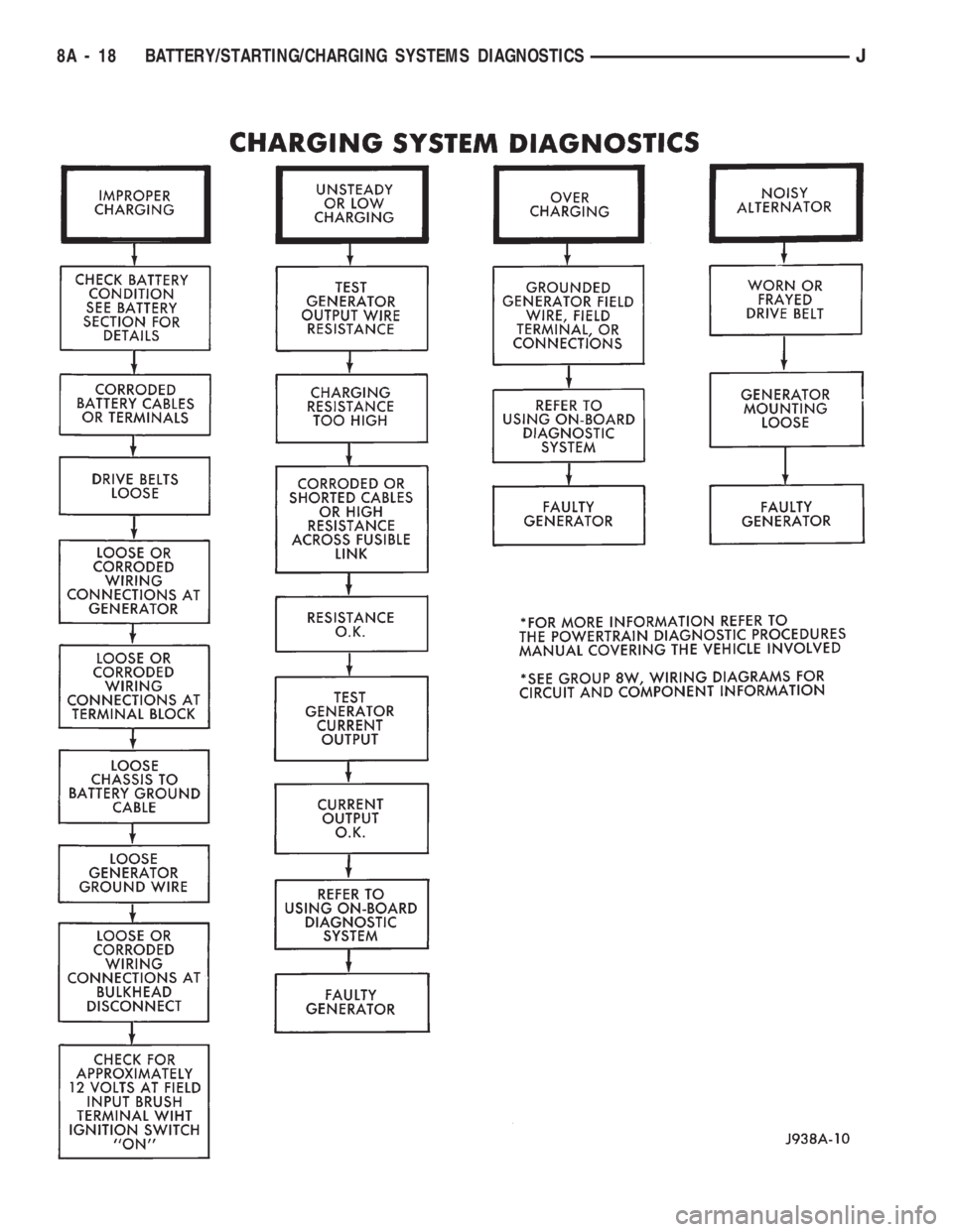
8A - 18 BATTERY/STARTING/CHARGING SYSTEMS DIAGNOSTICSJ
Page 292 of 1784
USING ON-BOARD DIAGNOSTIC SYSTEM
OPERATION OF ON-BOARD DIAGNOSTIC
(OBD) SYSTEM
The Powertrain Control Module (PCM) monitors
critical input and output circuits of the charging sys-
tem making sure they are OK. Some are checked
continuously and some are checked only under cer-
tain conditions.
If OBD system senses that one critical circuit is
bad during the monitoring cycle, it will put a diag-
nostic trouble code into memory. Each input and out-
put circuit monitored by the OBD system has its own
diagnostic trouble code. The diagnostic trouble code
(DTC) will stay in memory as long as the circuit con-
tinues to be bad. If the problem does not happen
again after the fault code is put into memory, the
PCM is programmed to clear the memory after 50 en-
gine starts.
DIAGNOSTIC TROUBLE CODES (DTC)
Diagnostic trouble codes are two-digit numbers
flashed on Malfunction Indicator (Check Engine)
Lamp that identify which circuit is bad. In most
cases they do not identify which component in a cir-
cuit is bad. A trouble code description can be read us-
ing the DRB scan tool. Refer to Group 14 - Fuel
Systems for more information. Therefore, a DTC is
only a symptom, not necessarily the cause for the
problem. In some cases, because of the design of the
driveability test procedure, a DTC can be the reason
for the problem. It is important that the test proce-
dure be followed to understand what caused the DTC
of the on-board diagnostic system to be set.
HOW TO USE MALFUNCTION INDICATOR (CHECK
ENGINE) LAMP FOR DIAGNOSTIC TROUBLE
CODES
To start this function, cycle the ignition switch ON-
OFF-ON-OFF-ON within 5 seconds and any trouble
code stored in the PCM will be displayed. The Mal-
function Indicator (Check Engine) Lamp will display
a DTC by flashing on and off. There is a short pause
between flashes and a longer pause between digits.
All codes displayed are two digit numbers with a 4
second pause between codes.
An example of a code is as follows:
(1) Lamp on for 2 seconds, then turns off.
(2) Lamp flashes 4 times pauses and then flashes 1
time.
(3) Lamp pauses for 4 seconds, flashes 4 times,
pauses and then flashes 7 times.
The 2 codes are 41 and 47. Any number of codes
can be displayed as long as they are in memory. The
lamp will flash until all are displayed (55 = End of
test).
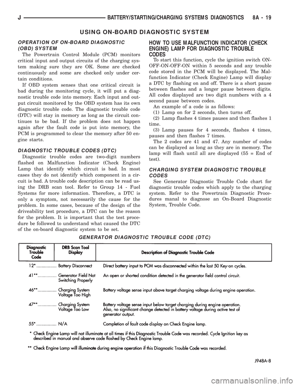
CHARGING SYSTEM DIAGNOSTIC TROUBLE
CODES
See Generator Diagnostic Trouble Code chart for
diagnostic trouble codes which apply to the charging
system. Refer to the Powertrain Diagnostic Proce-
dures manal to diagnose an On-Board Diagnostic
System, Trouble Code.
GENERATOR DIAGNOSTIC TROUBLE CODE (DTC)
JBATTERY/STARTING/CHARGING SYSTEMS DIAGNOSTICS 8A - 19
Page 294 of 1784
BATTERY/STARTER/GENERATOR SERVICE
CONTENTS
page page
BATTERY SERVICE PROCEDURES.......... 1
ENGINE STARTER MOTOR SERVICE
PROCEDURES......................... 4GENERATOR SERVICE PROCEDURES........ 7
SPECIFICATIONS....................... 10
BATTERY SERVICE PROCEDURES
GENERAL INFORMATION
This section covers battery removal and installa-
tion procedures only. For diagnostic procedures, refer
to Group 8A - Battery/Starting/Charging Systems Di-
agnostics.
BATTERY MAINTENANCE
(1) Inspect cable terminals for corrosion and dam-
age. Remove the corrosion using a wire brush, or
post and terminal cleaner, and a sodium bicarbonate/
water solution. Replace cables that have damaged or
deformed terminals.
Be sure filler caps or vents are installed when
washing battery to prevent solution from enter-
ing battery.
(2) Clean outside of battery case if the original
battery is to be installed. Clean top cover with di-
luted ammonia or a sodium bicarbonate/water solu-
tion to remove acid film. Flush with clean water.
Ensure that cleaning solution does not enter cells.
(3) Remove corrosion from the terminals with a
wire brush or post and terminal cleaner. Inspect the
case for cracks or other damage that would result in
leakage of electrolyte.
(4) Check electrolyte level in the battery. Use a
putty knife or other suitable wide tool to pry filler
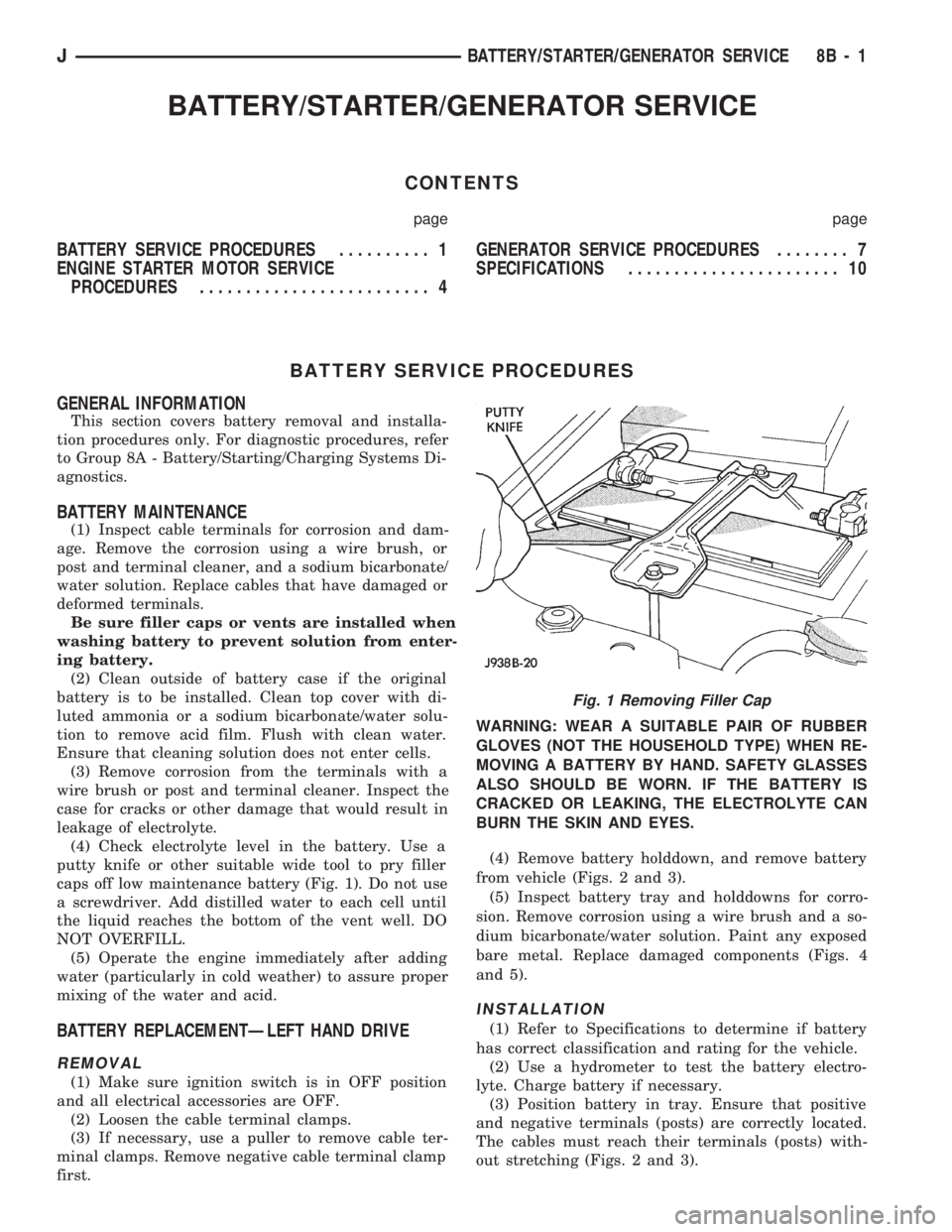
caps off low maintenance battery (Fig. 1). Do not use
a screwdriver. Add distilled water to each cell until
the liquid reaches the bottom of the vent well. DO
NOT OVERFILL.
(5) Operate the engine immediately after adding
water (particularly in cold weather) to assure proper
mixing of the water and acid.
BATTERY REPLACEMENTÐLEFT HAND DRIVE
REMOVAL
(1) Make sure ignition switch is in OFF position
and all electrical accessories are OFF.
(2) Loosen the cable terminal clamps.
(3) If necessary, use a puller to remove cable ter-
minal clamps. Remove negative cable terminal clamp
first.WARNING: WEAR A SUITABLE PAIR OF RUBBER
GLOVES (NOT THE HOUSEHOLD TYPE) WHEN RE-
MOVING A BATTERY BY HAND. SAFETY GLASSES
ALSO SHOULD BE WORN. IF THE BATTERY IS
CRACKED OR LEAKING, THE ELECTROLYTE CAN
BURN THE SKIN AND EYES.
(4) Remove battery holddown, and remove battery
from vehicle (Figs. 2 and 3).
(5) Inspect battery tray and holddowns for corro-
sion. Remove corrosion using a wire brush and a so-
dium bicarbonate/water solution. Paint any exposed
bare metal. Replace damaged components (Figs. 4
and 5).
INSTALLATION
(1) Refer to Specifications to determine if battery
has correct classification and rating for the vehicle.
(2) Use a hydrometer to test the battery electro-
lyte. Charge battery if necessary.
(3) Position battery in tray. Ensure that positive
and negative terminals (posts) are correctly located.
The cables must reach their terminals (posts) with-
out stretching (Figs. 2 and 3).
Fig. 1 Removing Filler Cap
JBATTERY/STARTER/GENERATOR SERVICE 8B - 1
Page 297 of 1784

ENGINE STARTER MOTOR SERVICE PROCEDURES
INDEX
page page
2.5L Starter General Information.............. 4
2.5L Starter Motor Removal/Installation......... 5
4.0L Starter General Information.............. 6
4.0L Starter Motor Removal/Installation......... 6General Information........................ 4
Park/Neutral Position Switch................. 6
Starter Relay Replacement.................. 4
GENERAL INFORMATION
This section will cover the starting system compo-
nent service procedures only. For diagnostic proce-
dures, refer to Group 8A - Battery/Starting/Charging
Systems Diagnostics.
Starting system components: battery, starter mo-
tor, starter relay, starter solenoid, ignition switch,
connecting wires and battery cables. A park/neutral
position switch is used with automatic transmissions.
STARTER RELAY REPLACEMENT
The starter relay is located in the Power Distribu-
tion Center (Figs. 1 and 2). Refer to underside of
Power Distribution Center cover for relay location.
(1) Disconnect negative cable from battery.
(2) Replace relay.
(3) Connect negative cable to battery.
(4) Test relay operation.
2.5L STARTER GENERAL INFORMATION
The 2.5L engine starter motor incorporates several
features to create an efficient, lightweight unit.
A planetary gear system (intermediate transmis-
sion) between the electric motor and pinion shaftmakes it possible to reduce the dimensions of the
starter. This also makes it possible to obtain a higher
rotational speed to produce the same torque at the
pinion.
The permanent magnet field consists of six two-
component high strength magnets. The magnets are
aligned according to their polarity and are perma-
nently fixed in the starter frame.
The brush holder plate consists of a plastic base-
plate with four tubular brush holders.
This unit is highly sensitive to hammering, shocks
and external pressure.
CAUTION: The starter motor MUST NOT BE
CLAMPED in a vise by the starter frame. Doing so
may damage the magnets. It may be clamped by the
mounting flange ONLY.
CAUTION: Do not connect starter motor incorrectly
when tests are being performed. The magnets may
be damaged and rendered unserviceable.
²Ensure cleanliness when performing repairs.
Fig. 1 Power Distribution CenterÐXJ
Fig. 2 Power Distribution CenterÐYJ
8B - 4 BATTERY/STARTER/GENERATOR SERVICEJ
Page 300 of 1784
GENERATOR SERVICE PROCEDURES
GENERAL
The generator is belt-driven by the engine. All en-
gines use serpentine drive. This section will cover
generator removal and installation. The generator is
not serviceable. Information covering on-vehicle test-
ing can be found in Group 8A - Battery/Starting/
Charging Systems Diagnostics.
GENERATOR REPLACEMENTÐLEFT HAND DRIVE
WARNING: FAILURE TO DISCONNECT NEGATIVE
CABLE FROM BATTERY BEFORE DISCONNECTING
RED (OUTPUT) WIRE CONNECTOR FROM GENER-
ATOR CAN RESULT IN INJURY.
ALL YJ AND XJ WITH 2.5L ENGINE
Belt tension is adjusted at the power steering pump
(or idler pulley if not equipped with power steering).
To replace generator:
(1) Disconnect negative cable from battery.
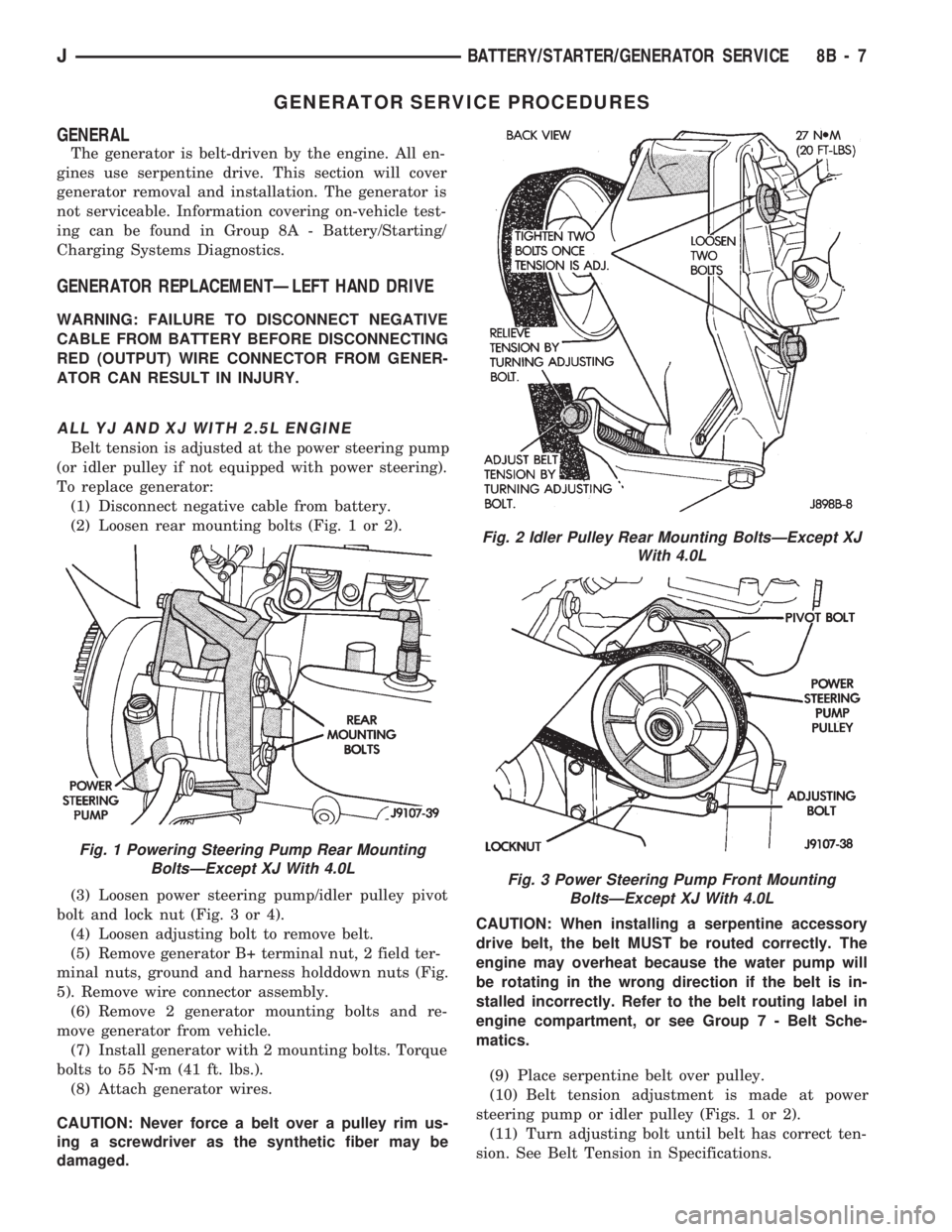
(2) Loosen rear mounting bolts (Fig. 1 or 2).
(3) Loosen power steering pump/idler pulley pivot
bolt and lock nut (Fig. 3 or 4).
(4) Loosen adjusting bolt to remove belt.
(5) Remove generator B+ terminal nut, 2 field ter-
minal nuts, ground and harness holddown nuts (Fig.
5). Remove wire connector assembly.
(6) Remove 2 generator mounting bolts and re-
move generator from vehicle.
(7) Install generator with 2 mounting bolts. Torque
bolts to 55 Nzm (41 ft. lbs.).
(8) Attach generator wires.
CAUTION: Never force a belt over a pulley rim us-
ing a screwdriver as the synthetic fiber may be
damaged.CAUTION: When installing a serpentine accessory
drive belt, the belt MUST be routed correctly. The
engine may overheat because the water pump will
be rotating in the wrong direction if the belt is in-
stalled incorrectly. Refer to the belt routing label in
engine compartment, or see Group 7 - Belt Sche-
matics.
(9) Place serpentine belt over pulley.
(10) Belt tension adjustment is made at power
steering pump or idler pulley (Figs. 1 or 2).
(11) Turn adjusting bolt until belt has correct ten-
sion. See Belt Tension in Specifications.
Fig. 1 Powering Steering Pump Rear Mounting
BoltsÐExcept XJ With 4.0L
Fig. 2 Idler Pulley Rear Mounting BoltsÐExcept XJ
With 4.0L
Fig. 3 Power Steering Pump Front Mounting
BoltsÐExcept XJ With 4.0L
JBATTERY/STARTER/GENERATOR SERVICE 8B - 7
Page 369 of 1784

GAUGE PACKAGE GENERAL INFORMATION
The gauge package contains 4 gauges and the 4
wheel drive indicator. The gauges have a common
battery feed from fuse #9 and ignition switch. Al-
though they have separate power sources, the 4
gauges share a common ground connection.
The voltmeter indicates electrical system voltage.
When the engine is not running, the voltage regis-
tered is from the battery. After the engine is started,
charging system voltage is indicated. In the gauge
package, the voltmeter forms a parallel connectionacross the battery feed and ground.
The remaining gauges - oil pressure, fuel and cool-
ant temperature - are connected to individual sender
units. Variable resistors in the senders will change
the amount of current allowed to flow through the
gauge coils. As current flow through the coils varies,
the position of the indicator needle also will vary.
The 4 gauges are connected to battery feed, ground
and the sender units through a printed circuit
mounted on the back of the gauge housing.
GAUGE PACKAGE DIAGNOSIS
ALL GAUGES INOPERATIVE (Fig. 15)
(1) Check the fuse #9. Replace as required.
(2) Turn ignition switch to ON and measure volt-
age at battery side of fuse #9. Meter should read bat-
tery voltage. If not, repair open from ignition switch.
(3) Unplug gauge package connector from gauge
package.
(4) Turn ignition switch to OFF and measure resis-
tance from instrument cluster connector terminals 1
and 13 to a clean chassis ground. Meter should read
zero ohms. If not, repair open to ground.
(5) Turn ignition switch to ON and measure volt-
age at instrument cluster connector terminals 2 and
12. Meter should read battery voltage. If not, repair
open from fuse panel.
ONE GAUGE INOPERATIVE
Does not apply to voltmeter.
OIL PRESSURE SENDER
(1) Turn ignition switch to ON.
(2) Unplug oil pressure sender connector from oil
pressure sender.
(3) Touch connector to engine block (ground).
Gauge should read at low end of scale.
(4) When connector is NOT touching ground (open
circuit) gauge should read at high end of scale. If OK
replace sender. If not, proceed with step 5.
(5) Check circuit between sender and gauge for an
open. Repair as required. If wiring is OK, replace
gauge.
COOLANT TEMPERATURE SENDER
(1) Turn ignition switch to ON.
(2) Unplug coolant temperature sender connector
from coolant temperature sender.
(3) Touch connector to engine block (ground).
Gauge should read at high end of scale.
(4) When connector is NOT touching ground (open
circuit) gauge should read at low end of scale. If OK
replace sender. If not, proceed with step 5.
(5) Check circuit between sender and gauge for an
open. Repair as required. If wiring is OK, replace
gauge.
FUEL GAUGE SENDER
(1) Turn ignition switch to ON.
(2) Separate fuel gauge sender connector from fuel
gauge sender near tank.
(3) Ground the center wire of the body harness
side of the connector. The gauge should read at low
end of scale. If OK, check sending unit (step 4). If
not, check circuit between connector and gauge. Re-
pair as required. If circuit is OK, replace gauge.
(4) Turn ignition switch to OFF.
(5) Measure resistance from fuel gauge sender con-
nector center terminal to a clean chassis ground.
Meter readings should correspond to those shown in
Specifications. If not OK, replace sender. If OK, re-
pair open from fuel gauge sender connector to
ground.
PRINTED CIRCUIT
(1) Turn ignition switch to ON.
(2) Unplug gauge package connector from gauge
package.
(3) Measure resistance from gauge package termi-
nal 12 (fuel and coolant temperature gauge) or from
terminal 2 (voltmeter and oil pressure gauge) to
gauge battery terminal. Meter should read zero
ohms. If not, replace/repair printed circuit.
(4) Measure resistance from gauge package termi-
nal 13 (fuel and coolant temperature gauge) or from
terminal 1 (voltmeter and oil pressure gauge) to
gauge ground terminal. Meter should read zero
ohms. If not, replace/repair printed circuit. If zero
ohms, replace gauge.
GAUGE CALIBRATION VALUES
Use the charts in Specifications. The calibration of
the gauge can be checked. If the indicator needle is
not in the correct position, replace the gauge.
4WD INDICATOR
The four-wheel drive indicator lamp circuit is com-
pleted by the Command-Trac switch located below
the battery.
8E - 22 YJ INSTRUMENT PANEL AND GAUGESJ
Page 495 of 1784

WIRE CODE IDENTIFICATION
Each wire shown in the diagrams contains a code
(Fig. 3) which identifies the main circuit, part of the
main circuit, gauge of wire, and color. The color is
shown as a two letter code which can be identified by
referring to the Wire Color Code Chart (Fig. 4). If the
wire has a tracer and it is a standard color an aster-
isk will follow the main wire color. If the tracer is
non-standard the main wire color will have a slash (/)
after it followed by the tracer color.
CIRCUIT IDENTIFICATION
All circuits in the diagrams use an alpha/numeric
code to identify the wire and its function. To identify
which circuit code applies to a system, refer to the
Circuit Identification Code Chart. This chart shows
the main circuits only and does not show the second-
ary codes that may apply to some models.
LOCATING A SYSTEM
To locate a system or component in the diagrams,
refer to the alphabetical index at the front of the di-
agrams. Determine the diagram sheet number. Sheet
numbers are located at the lower right or left handcorner of each sheet.Page numbers at the top of
the page do not apply to diagram sheets.
The index identifies the main system and all com-
ponents that relate to that system. There are also
sections of the index that identify specific compo-
nents only (for example modules, lamps, etc.). Refer
to a components name in the index if you are unclear
as to what a system may be called.
Diagram sheets are arranged starting with the bat-
tery and fuses. Then working into charging, starting,
and ignition systems. After this they start at the
front of the vehicle and work to rear. The diagrams
end with connector identification pages.
COMPONENT IDENTIFICATION
When looking for a components location in the vehicle
refer to the Component Identification section index.
This section shows the wire harness routing and the
components location in the vehicle. When using this sec-
tion refer to the wiring diagrams for the general loca-
tion of the component. Then use the component
identification index to locate the proper figure number.
SPLICE LOCATIONS
Splice locations are indicated in the diagrams by a
diamond with a splice circuit code within it (Fig. 5
example 1). If there is more than one splice per cir-
cuit a small box will be connected to it with the
splice number in it (Fig. 5 example 2).
To locate a splice in the wiring harness determine
the splice number from the wiring diagrams then re-
fer to the splice location index. This section shows
the general location of the splice in the harness.
Fig. 2 Secondary Ignition Wiring 4.0L
Fig. 3 Wire Color Code Identification
Fig. 4 Wire Color Code Chart
8W - 2 WIRING DIAGRAMSJ
Page 566 of 1784
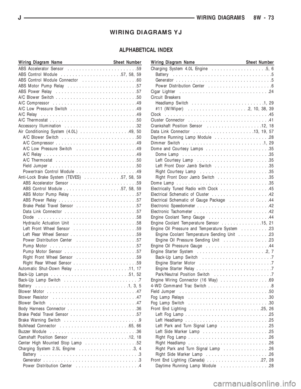
WIRING DIAGRAMS YJ
ALPHABETICAL INDEX
Wiring Diagram Name Sheet Number
ABS Accelerator Sensor........................59
ABS Control Module.....................57, 58, 59
ABS Control Module Connector...................60
ABS Motor Pump Relay........................57
ABS Power Relay............................57
A/C Blower Switch............................50
A/C Compressor.............................49
A/C Low Pressure Switch.......................49
A/C Relay.................................49
A/C Thermostat..............................50
Accessory Illumination.........................32
Air Conditioning System (4.0L).................49, 50
A/C Blower Switch..........................50
A/C Compressor............................49
A/C Low Pressure Switch.....................49
A/C Relay................................49
A/C Thermostat............................50
Field Jumper..............................50
Powertrain Control Module.....................49
Anti-Lock Brake System (TEVES).............57, 58, 59
ABS Accelerator Sensor.......................59
ABS Control Module....................57, 58, 59
ABS Motor Pump Relay.......................57
ABS Power Relay...........................57
Brake Pedal Travel Sensor.....................57
Data Link Connector.........................57
Diode..................................58
Hydraulic Actuation Unit......................58
Left Front Wheel Sensor......................59
Left Rear Wheel Sensor.......................59
Power Distribution Center.....................57
Pump Motor..............................57
Pump Motor Sensor.........................57
Right Front Wheel Sensor.....................59
Right Rear Wheel Sensor......................59
Automatic Shut-Down Relay...................11, 17
Back-Up Lamps...........................51, 52
Back-Up Lamp Switch..........................7
Battery................................1,3,5
Blower Motor...............................47
Blower Resistor.............................47
Blower Switch..............................47
Body Harness Connector........................36
Brake Pedal Travel Sensor.......................57
Brake Warning Switch..........................9
Bulkhead Connector........................65, 66
Buzzer Module..............................36
Camshaft Position Sensor....................12, 18
Center High Mounted Stop Lamp..................52
Charging System 2.5L Engine...................3,4
Battery..................................3
Generator.................................3
Power Distribution Center......................4Wiring Diagram Name Sheet Number
Charging System 4.0L Engine...................5,6
Battery..................................5
Generator.................................5
Power Distribution Center......................6
Cigar Lighter...............................24
Circuit Breakers
Headlamp Switch.........................1,29
#11 (W/Wiper).....................2,10,38,39
Clock....................................45
Cluster Connector............................41
Crankshaft Position Sensor...................12, 18
Data Link Connector.....................13, 19, 57
Daytime Running Lamp Module...................28
Dimmer Switch............................1,29
Dome and Courtesy Lamps......................35
Dome Lamp..............................35
Left Courtesy Lamp.........................35
Left Front Door Jamb Switch...................35
Right Courtesy Lamp........................35
Right Front Door Jamb Switch..................35
Dome Lamp................................35
Electrically Tuned Radio with Clock.................45
Electrical Schematic of Cluster....................42
Electrical Schematic of Gauge Package..............44
Electronic Speedometer.........................42
Electronic Tachometer..........................42
Engine Coolant Temp Gauge.....................44
Engine Coolant Temperature Sensor..............15, 21
Engine Oil Pressure and Temperature System..........23
Engine Coolant Temperature Sending Unit...........23
Engine Oil Pressure Sending Unit................23
Engine Oil Pressure Gauge......................44
Engine Starter System........................2,7
Back-Up Lamp Switch........................7
Engine Starter Motor.........................7
Engine Starter Relay..........................7
Park/Neutral Position Switch....................7
Engine Wiring Connector (16 Way).................69
4-WD Command Trac Switch......................8
Field Jumper...............................50
Fog Lamp Relays............................30
Fog Lamp Switch............................30
Front End Lighting.........................25, 26
Left Fog Lamp.............................25
Left Headlamp.............................25
Left Park and Turn Signal Lamp.................25
Left Side Marker Lamp.......................25
Right Fog Lamp............................26
Right Headlamp............................26
Right Park and Turn Signal Lamp................26
Right Side Marker Lamp......................26
Front End Lighting (Canada)...................27, 28
Daytime Running Lamp Module.................28
JWIRING DIAGRAMS 8W - 73