Page 1286 of 1784
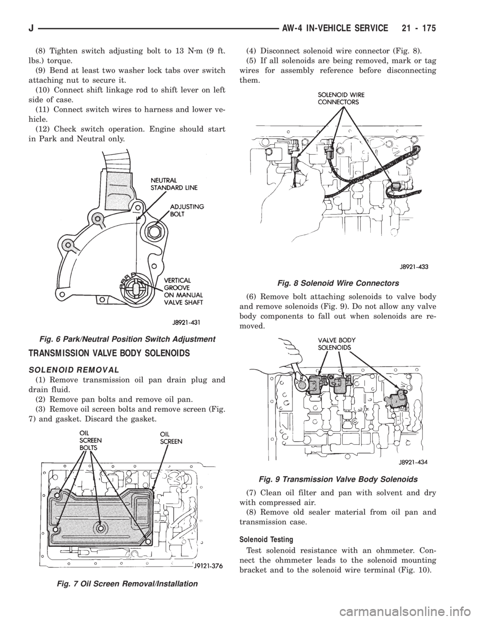
(8) Tighten switch adjusting bolt to 13 Nzm(9ft.
lbs.) torque.
(9) Bend at least two washer lock tabs over switch
attaching nut to secure it.
(10) Connect shift linkage rod to shift lever on left
side of case.
(11) Connect switch wires to harness and lower ve-
hicle.
(12) Check switch operation. Engine should start
in Park and Neutral only.
TRANSMISSION VALVE BODY SOLENOIDS
SOLENOID REMOVAL
(1) Remove transmission oil pan drain plug and
drain fluid.
(2) Remove pan bolts and remove oil pan.
(3) Remove oil screen bolts and remove screen (Fig.
7) and gasket. Discard the gasket.(4) Disconnect solenoid wire connector (Fig. 8).
(5) If all solenoids are being removed, mark or tag
wires for assembly reference before disconnecting
them.
(6) Remove bolt attaching solenoids to valve body
and remove solenoids (Fig. 9). Do not allow any valve
body components to fall out when solenoids are re-
moved.
(7) Clean oil filter and pan with solvent and dry
with compressed air.
(8) Remove old sealer material from oil pan and
transmission case.
Solenoid Testing
Test solenoid resistance with an ohmmeter. Con-
nect the ohmmeter leads to the solenoid mounting
bracket and to the solenoid wire terminal (Fig. 10).
Fig. 8 Solenoid Wire Connectors
Fig. 9 Transmission Valve Body Solenoids
Fig. 6 Park/Neutral Position Switch Adjustment
Fig. 7 Oil Screen Removal/Installation
JAW-4 IN-VEHICLE SERVICE 21 - 175
Page 1316 of 1784
During overhaul assembly operations, lubricate the
transmission components with Jeep or Mopar Mer-
conŸ automatic transmission fluid or petroleum jelly
as indicated. Petroleum jelly should be used to prelu-
bricate thrust bearings, washers and races. It can
also be used to hold parts in position during assem-
bly.
Soak replacement clutch and brake pack com-
ponents in transmission fluid for at least 30
minutes before installation.
MANUAL VALVE SHAFT OVERHAUL
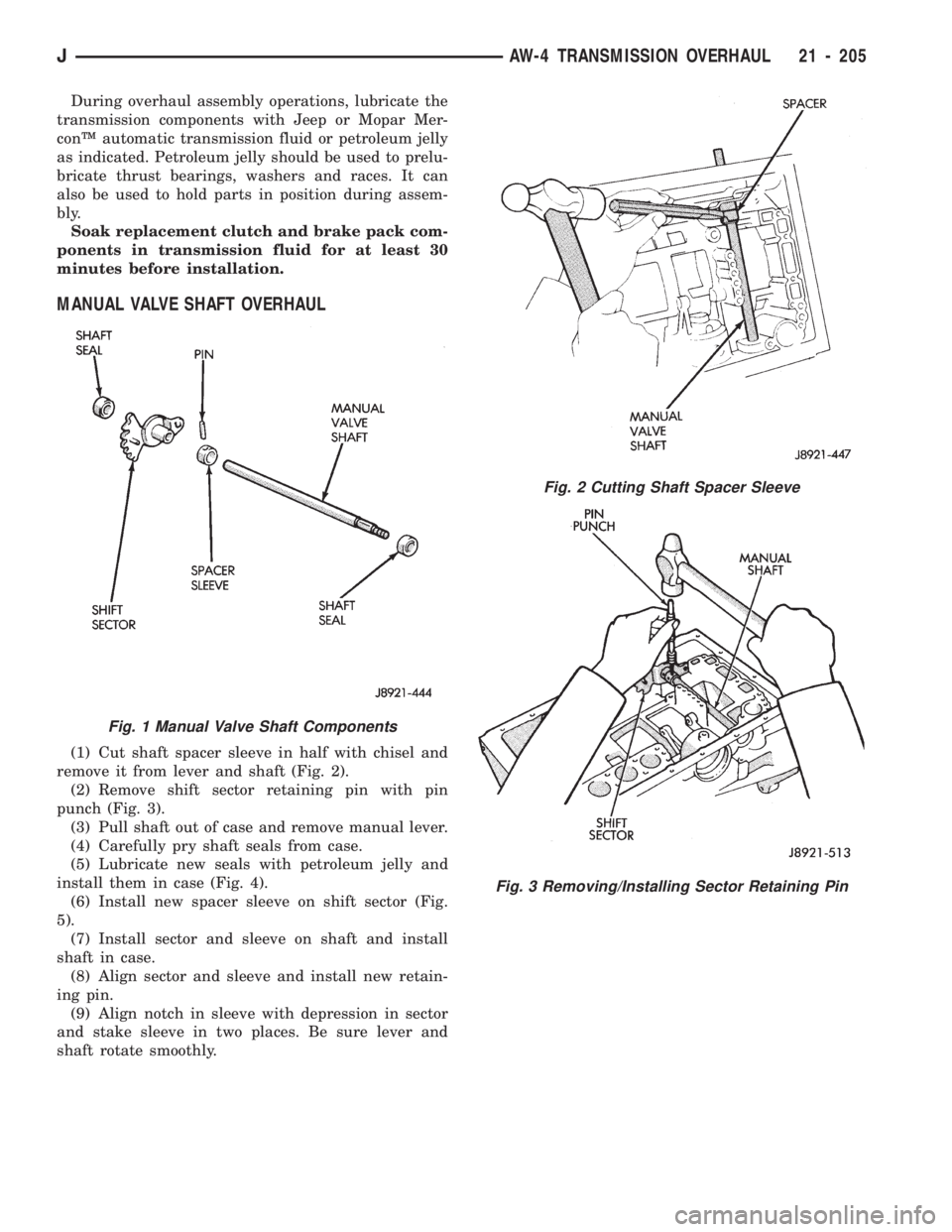
(1) Cut shaft spacer sleeve in half with chisel and
remove it from lever and shaft (Fig. 2).
(2) Remove shift sector retaining pin with pin
punch (Fig. 3).
(3) Pull shaft out of case and remove manual lever.
(4) Carefully pry shaft seals from case.
(5) Lubricate new seals with petroleum jelly and
install them in case (Fig. 4).
(6) Install new spacer sleeve on shift sector (Fig.
5).
(7) Install sector and sleeve on shaft and install
shaft in case.
(8) Align sector and sleeve and install new retain-
ing pin.
(9) Align notch in sleeve with depression in sector
and stake sleeve in two places. Be sure lever and
shaft rotate smoothly.
Fig. 1 Manual Valve Shaft Components
Fig. 2 Cutting Shaft Spacer Sleeve
Fig. 3 Removing/Installing Sector Retaining Pin
JAW-4 TRANSMISSION OVERHAUL 21 - 205
Page 1356 of 1784
roded. Replace valves, plugs or sleeves that are
scored or worn. Replace oil strainers if cut, torn or
damaged in any way.
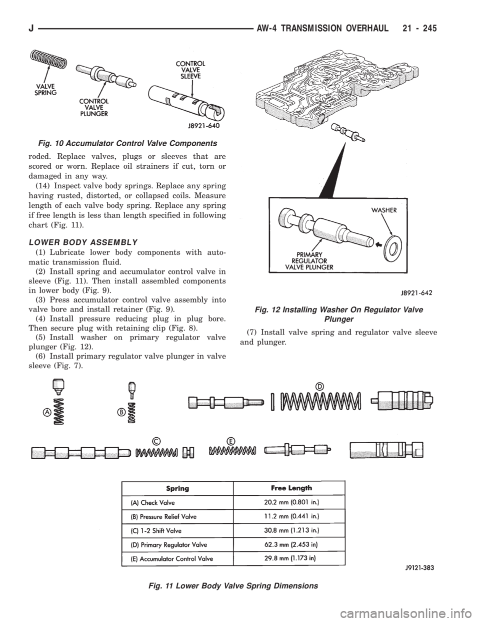
(14) Inspect valve body springs. Replace any spring
having rusted, distorted, or collapsed coils. Measure
length of each valve body spring. Replace any spring
if free length is less than length specified in following
chart (Fig. 11).
LOWER BODY ASSEMBLY
(1) Lubricate lower body components with auto-
matic transmission fluid.
(2) Install spring and accumulator control valve in
sleeve (Fig. 11). Then install assembled components
in lower body (Fig. 9).
(3) Press accumulator control valve assembly into
valve bore and install retainer (Fig. 9).
(4) Install pressure reducing plug in plug bore.
Then secure plug with retaining clip (Fig. 8).
(5) Install washer on primary regulator valve
plunger (Fig. 12).
(6) Install primary regulator valve plunger in valve
sleeve (Fig. 7).(7) Install valve spring and regulator valve sleeve
and plunger.
Fig. 11 Lower Body Valve Spring Dimensions
Fig. 10 Accumulator Control Valve Components
Fig. 12 Installing Washer On Regulator Valve
Plunger
JAW-4 TRANSMISSION OVERHAUL 21 - 245
Page 1395 of 1784
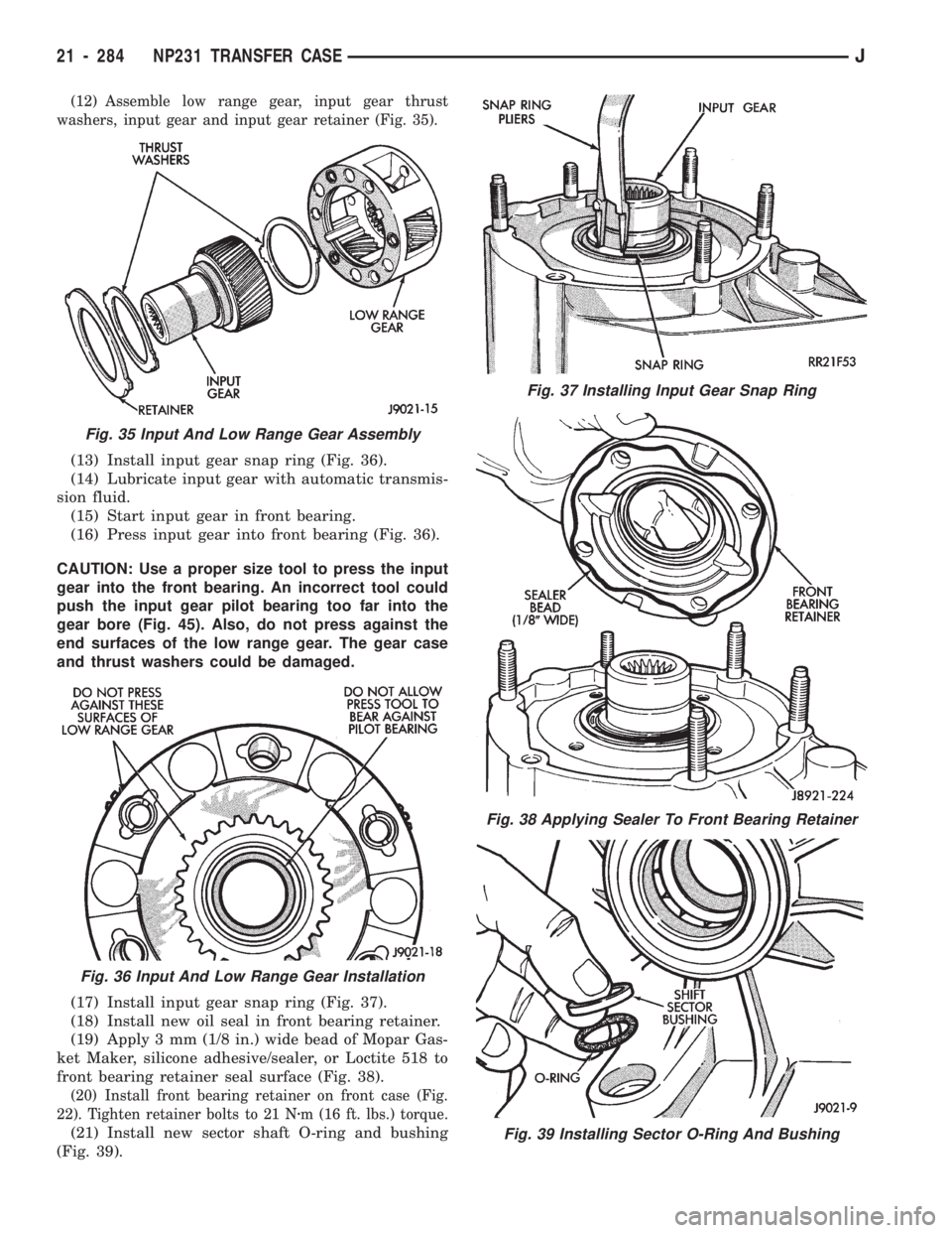
(12) Assemble low range gear, input gear thrust
washers, input gear and input gear retainer (Fig. 35).
(13) Install input gear snap ring (Fig. 36).
(14) Lubricate input gear with automatic transmis-
sion fluid.
(15) Start input gear in front bearing.
(16) Press input gear into front bearing (Fig. 36).
CAUTION: Use a proper size tool to press the input
gear into the front bearing. An incorrect tool could
push the input gear pilot bearing too far into the
gear bore (Fig. 45). Also, do not press against the
end surfaces of the low range gear. The gear case
and thrust washers could be damaged.
(17) Install input gear snap ring (Fig. 37).
(18) Install new oil seal in front bearing retainer.
(19) Apply 3 mm (1/8 in.) wide bead of Mopar Gas-
ket Maker, silicone adhesive/sealer, or Loctite 518 to
front bearing retainer seal surface (Fig. 38).
(20) Install front bearing retainer on front case (Fig.
22). Tighten retainer bolts to 21 Nzm (16 ft. lbs.) torque.
(21) Install new sector shaft O-ring and bushing
(Fig. 39).
Fig. 37 Installing Input Gear Snap Ring
Fig. 38 Applying Sealer To Front Bearing Retainer
Fig. 39 Installing Sector O-Ring And Bushing
Fig. 35 Input And Low Range Gear Assembly
Fig. 36 Input And Low Range Gear Installation
21 - 284 NP231 TRANSFER CASEJ
Page 1401 of 1784
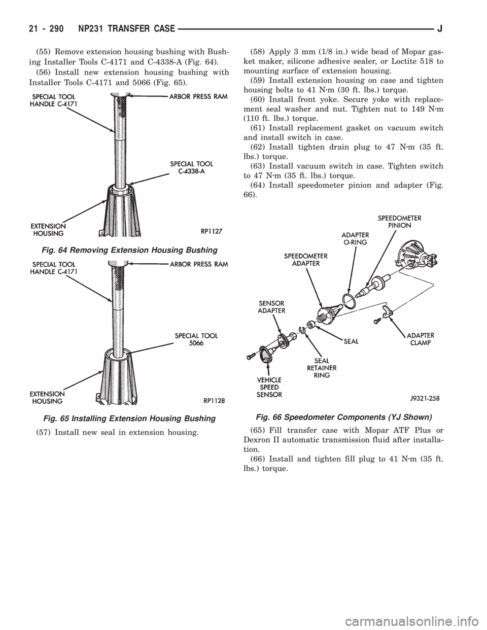
(55) Remove extension housing bushing with Bush-
ing Installer Tools C-4171 and C-4338-A (Fig. 64).
(56) Install new extension housing bushing with
Installer Tools C-4171 and 5066 (Fig. 65).
(57) Install new seal in extension housing.(58) Apply 3 mm (1/8 in.) wide bead of Mopar gas-
ket maker, silicone adhesive sealer, or Loctite 518 to
mounting surface of extension housing.
(59) Install extension housing on case and tighten
housing bolts to 41 Nzm (30 ft. lbs.) torque.
(60) Install front yoke. Secure yoke with replace-
ment seal washer and nut. Tighten nut to 149 Nzm
(110 ft. lbs.) torque.
(61) Install replacement gasket on vacuum switch
and install switch in case.
(62) Install tighten drain plug to 47 Nzm (35 ft.
lbs.) torque.
(63) Install vacuum switch in case. Tighten switch
to 47 Nzm (35 ft. lbs.) torque.
(64) Install speedometer pinion and adapter (Fig.
66).
(65) Fill transfer case with Mopar ATF Plus or
Dexron II automatic transmission fluid after installa-
tion.
(66) Install and tighten fill plug to 41 Nzm (35 ft.
lbs.) torque.
Fig. 64 Removing Extension Housing Bushing
Fig. 65 Installing Extension Housing BushingFig. 66 Speedometer Components (YJ Shown)
21 - 290 NP231 TRANSFER CASEJ
Page 1417 of 1784
Inspect the differential gears, thrust washers and
case halves. Replace the mainshaft gear if the gear
teeth or the brass ring on the underside of the gear
are damaged. Replace the differential as an assembly
if the gears, case halves, or the pins in the lower case
half are damaged.
Inspect the case halves, extension housing and re-
tainers for cracks, porosity, or damaged sealing sur-
faces. Inspect the shafts, gears, chain and shift
components for wear or damage.
Inspect all of the transfer case bearings for wear,
roughness, pitting, or galling. Replace worn or dam-
aged bearings as outlined in the assembly section.
TRANSFER CASE ASSEMBLY
(1) Lubricate the transfer case components with
automatic transmission fluid or petroleum jelly
(where indicated) during assembly.
CAUTION: The bearing bores in various transfer
case components contain oil feed holes. Be sure re-
placement bearings do not block these feed holes.
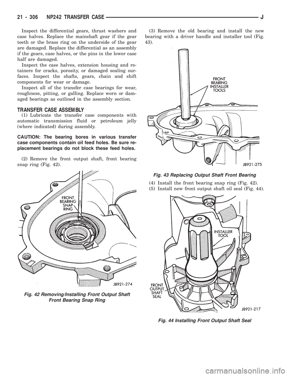
(2) Remove the front output shaft, front bearing
snap ring (Fig. 42).(3) Remove the old bearing and install the new
bearing with a driver handle and installer tool (Fig.
43).
(4) Install the front bearing snap ring (Fig. 42).
(5) Install new front output shaft oil seal (Fig. 44).
Fig. 42 Removing/Installing Front Output Shaft
Front Bearing Snap Ring
Fig. 43 Replacing Output Shaft Front Bearing
Fig. 44 Installing Front Output Shaft Seal
21 - 306 NP242 TRANSFER CASEJ
Page 1419 of 1784
(11) Assemble low range gear, input gear thrust
washers, input gear and input gear retainer (Fig. 49).
(12) Install low range gear snap ring (Fig. 50).
(13) Lubricate input gear and low range gears with
automatic transmission fluid.
(14) Start the input gear shaft into the front case
bearing.
(15) Press the input gear shaft into the front bear-
ing.CAUTION: Be sure the input gear installer tool is
the proper size. The wrong size tool could push the
input gear pilot bearing too far into the gear bore
(Fig. 51). Also, do not press against the end sur-
faces of the low range gear. The gear case and
thrust washers could be damaged.
(16) Install new input gear snap ring (Fig. 52).
Fig. 49 Low Range And Input Gear Assembly
Fig. 50 Install Low Range Gear Snap Ring
Fig. 51 Input Gear Installation
Fig. 52 Install Input Gear Snap Ring
21 - 308 NP242 TRANSFER CASEJ
Page 1421 of 1784
(24) Position low range fork and hub in case. Be
sure low range fork pin is engaged in the shift sector
slot (Fig. 57).
(25) Lubricate differential components with auto-
matic transmission fluid.
(26) Install sprocket gear in differential bottom
case (Fig. 58).(27) Install differential planet gears and new
thrust washers (Fig. 59).Be sure thrust washers
are installed at top and bottom of each planet
gear.
(28) Install differential mainshaft gear (Fig. 59).
(29) Align and position differential top case on bot-
tom case (Fig. 60). Align using scribe marks made at
disassembly.
(30) Install and tighten the differential case bolts
to specified torque.
Fig. 57 Positioning Low Range Fork
Fig. 58 Installing Differential Sprocket Gear
Fig. 59 Installing Mainshaft And Planet Gears
Fig. 60 Differential Case Assembly
21 - 310 NP242 TRANSFER CASEJ