1994 JEEP CHEROKEE washer fluid
[x] Cancel search: washer fluidPage 328 of 1784
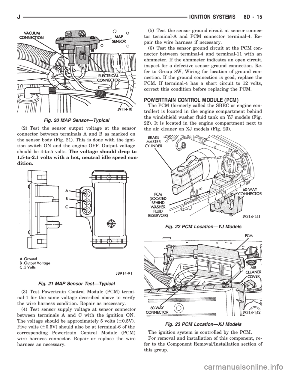
(2) Test the sensor output voltage at the sensor
connector between terminals A and B as marked on
the sensor body (Fig. 21). This is done with the igni-
tion switch ON and the engine OFF. Output voltage
should be 4-to-5 volts.The voltage should drop to
1.5-to-2.1 volts with a hot, neutral idle speed con-
dition.
(3) Test Powertrain Control Module (PCM) termi-
nal-1 for the same voltage described above to verify
the wire harness condition. Repair as necessary.
(4) Test sensor supply voltage at sensor connector
between terminals A and C with the ignition ON.
The voltage should be approximately 5 volts (60.5V).
Five volts (60.5V) should also be at terminal-6 of the
corresponding Powertrain Control Module (PCM)
wire harness connector. Repair or replace the wire
harness as necessary.(5) Test the sensor ground circuit at sensor connec-
tor terminal-A and PCM connector terminal-4. Re-
pair the wire harness if necessary.
(6) Test the sensor ground circuit at the PCM con-
nector between terminal-4 and terminal-11 with an
ohmmeter. If the ohmmeter indicates an open circuit,
inspect for a defective sensor ground connection. Re-
fer to Group 8W, Wiring for location of ground con-
nection. If the ground connection is good, replace the
PCM. If terminal-4 has a short circuit to 12 volts,
correct this condition before replacing the PCM.
POWERTRAIN CONTROL MODULE (PCM)
The PCM (formerly called the SBEC or engine con-
troller) is located in the engine compartment behind
the windshield washer fluid tank on YJ models (Fig.
22). It is located in the engine compartment next to
the air cleaner on XJ models (Fig. 23).
The ignition system is controlled by the PCM.
For removal and installation of this component, re-
fer to the Component Removal/Installation section of
this group.
Fig. 20 MAP SensorÐTypical
Fig. 21 MAP Sensor TestÐTypical
Fig. 22 PCM LocationÐYJ Models
Fig. 23 PCM LocationÐXJ Models
JIGNITION SYSTEMS 8D - 15
Page 341 of 1784
INSTALLATION
(1) Install MAP sensor to dash panel and secure
with mounting nuts.
(2) Install the MAP sensor vacuum supply hose.
(3) Connect the MAP sensor electrical connector.
OXYGEN (O2S) SENSOR
For diagnostics and removal/installation proce-
dures, refer to Group 14, Fuel Systems, in this man-
ual.
POWERTRAIN CONTROL MODULE (PCM)
The PCM was formerly referred to as the SBEC or
engine controller.
XJ MODELS
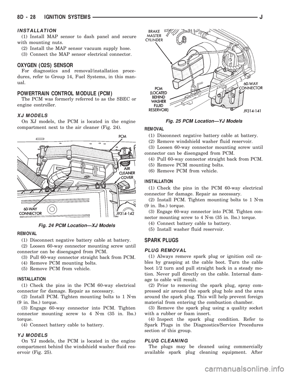
On XJ models, the PCM is located in the engine
compartment next to the air cleaner (Fig. 24).
REMOVAL
(1) Disconnect negative battery cable at battery.
(2) Loosen 60-way connector mounting screw until
connector can be disengaged from PCM.
(3) Pull 60-way connector straight back from PCM.
(4) Remove PCM mounting bolts.
(5) Remove PCM from vehicle.
INSTALLATION
(1) Check the pins in the PCM 60-way electrical
connector for damage. Repair as necessary.
(2) Install PCM. Tighten mounting bolts to 1 Nzm
(9 in. lbs.) torque.
(3) Engage 60-way connector into PCM. Tighten
connector mounting screw to 4 Nzm (35 in. lbs.)
torque.
(4) Connect battery cable to battery.
YJ MODELS
On YJ models, the PCM is located in the engine
compartment behind the windshield washer fluid res-
ervoir (Fig. 25).REMOVAL
(1) Disconnect negative battery cable at battery.
(2) Remove windshield washer fluid reservoir.
(3) Loosen 60-way connector mounting screw until
connector can be disengaged from PCM.
(4) Pull 60-way connector straight back from PCM.
(5) Remove PCM mounting bolts.
(6) Remove PCM from vehicle.
INSTALLATION
(1) Check the pins in the PCM 60-way electrical
connector for damage. Repair as necessary.
(2) Install PCM. Tighten mounting bolts to 1 Nzm
(9 in. lbs.) torque.
(3) Engage 60-way connector into PCM. Tighten con-
nector mounting screw to 4 Nzm (35 in. lbs.) torque.
(4) Connect battery cable to battery.
(5) Install washer fluid reservoir.
SPARK PLUGS
PLUG REMOVAL
(1) Always remove spark plug or ignition coil ca-
bles by grasping at the cable boot. Turn the cable
boot 1/2 turn and pull straight back in a steady mo-
tion. Never pull directly on the cable. Internal dam-
age to cable will result.
(2) Prior to removing the spark plug, spray com-
pressed air around the spark plug hole and the area
around the spark plug. This will help prevent foreign
material from entering the combustion chamber.
(3) Remove the spark plug using a quality socket
with a rubber or foam insert.
(4) Inspect the spark plug condition. Refer to
Spark Plugs in the Diagnostics/Service Procedures
section of this group.
PLUG CLEANING
The plugs may be cleaned using commercially
available spark plug cleaning equipment. After
Fig. 24 PCM LocationÐXJ Models
Fig. 25 PCM LocationÐYJ Models
8D - 28 IGNITION SYSTEMSJ
Page 351 of 1784

(3) Connect a jumper between terminal A and B on
the body half of the fuel gauge sender connector. The
gauge should move to F. If gauge is OK, replace
sender. If not, go to step 4.
(4) Measure resistance of sender. Meter should
read 105 to 5 ohms. If OK, go to step 5. If not, re-
place sender.
(5) Check for an open between sender connector
and gauge. If OK, replace gauge. If not, repair open
to gauge.
LOW FUEL WARNING INOPERATIVE
(1) Turn ignition switch to ON.
(2) Disconnect terminal B1 of the instrument clus-
ter connector. Wait at least 10 seconds. Lamp (LED)
should light. If OK, replace sender. If not, replace
low fuel warning module.
UPSHIFT INDICATOR INOPERATIVE
(1) Turn ignition switch to ON.
(2) Ground pin 7 of connector B. Lamp should
light. If not, replace bulb. If OK, continue with
step 3.
(3) Turn ignition switch to OFF. Check for conti-
nuity between connector B pin 2 and pin 54 of the
Powertrain Control Module. If OK, replace PCM. If
not, repair open.
BRAKE INDICATOR INOPERATIVE
(1) Turn ignition switch to ON. Apply parking
brake, brake warning switch connector unplugged.
(2) Jumper brake warning switch connector termi-
nal B to ground. Lamp should light. If bulb is OK,
repair open to indicator.
(3) Turn ignition switch to OFF. Measure resis-
tance between brake warning switch connector ter-
minal A and ground. Meter should read zero ohms. If
OK, check switch and/or brake system. If not, repair
open to park brake switch ground.
4WD INDICATOR INOPERATIVE
(1) Apply parking brake, start engine, vehicle in
4WD Lock or 4WD.
(2) Unplug switch and touch harness side of wire
to ground. Lamp should light. If OK, check switch
operation, replace if bad. If bulb is OK, repair open
to indicator.
LOW WASHER INDICATOR INOPERATIVE
(1) Turn ignition switch to ON.
(2) Jumper 12 volts to fluid level switch connector
terminal B. Lamp should light. If not, go to step 3.
(3) Measure resistance between terminal B and
ground. Meter should read zero ohms. If not, repair
open to bulb. If OK, go to step 4.
(4) Measure voltage at fluid level switch connector
terminal A. Meter should read battery voltage. If
OK, replace switch. If not, repair open to fuse.
MALFUNCTION INDICATOR LAMP (CHECK ENGINE)
(1) Turn ignition switch to ON.
(2) Jumper Powertrain Control Module terminal 2
to ground. Lamp should light. If bulb is OK, check
for open to instrument cluster connector terminal 2.
ANTI-LOCK INDICATOR
(1) Turn ignition switch to ON.
(2) Jumper instrument cluster connector terminal
6 to ground. Lamp should light. If bulb is OK, check
wiring for an open to module. Refer to Group 5 -
Brakes.
SEAT BELT INDICATOR
Jumper instrument cluster connector terminal 15
to 12 volts. Lamp should light. If not, replace bulb. If
OK, check wiring for an open to buzzer module. Re-
fer to Group 8U - Chime/Buzzer Warning Systems.
RADIO/CLOCK ILLUMINATION
With the ignition switch in ACCESSORY or ON,
power comes from the radio fuse. It then goes
through the normally closed contacts of the radio il-
lumination relay to the radio at connector terminal
11.
Pulling the headlamp switch to ON energizes the
radio illumination relay. This closes the normally
open contacts of the relay, and the brightness for the
radio display is controlled by the headlamp switch
rheostat. The back-lighting for the radio is also con-
trolled by the headlamp rheostat through radio con-
nector terminal 10.
Refer to Group 8F - Audio Systems, for radio illu-
mination relay diagnosis.
INSTRUMENT PANEL LAMPS
Voltage is supplied at all times from the 40 amp
Maxi fuse (located in the Power Distribution Center)
through the park lamps fuse to the headlamp switch.
The circuit continues through the instrument lamps
fuse to the individual instrument panel lamps to
ground. Lamp brightness is controlled by turning the
headlamp switch knob.
DIAGNOSIS
(1) Turn parking lamps ON.
(2) Check park lamps fuse. Replace as required.
(3) Check instrument lamps fuse. Replace as re-
quired.
(4) Measure voltage at battery side of instrument
lamps fuse with rheostat turned counterclockwise to
clockwise (LO to HI). Meter should read zero volts to
battery voltage. If not, replace headlamp switch.
(5) Measure resistance at ground side of instru-
ment lamps fuse with parking lamps OFF. Meter
should read almost zero ohms (except bulb filament).
If not, repair open to ground. If zero ohms, 12 volt
supply wire from fuse is shorted to ground, repair short.
8E - 4 XJ INSTRUMENT PANEL AND GAUGESJ
Page 644 of 1784
Wiring Diagram Name Sheet Number
Fuse #15...............................1,41
Fuse #17...........................2,10,55,74
Fuse #18...............................1,66
Fuse #19.............................1,41,47
Gauges
Engine Coolant Temperature Gauge...........59,60,61
Engine Oil Pressure Gauge.................59,60,61
Fuel Gauge...........................59,60,61
G Sensor..................................30
Generator.................................5,6
Glove Box Lamp.............................49
Hazard Flasher............................35,46
Headlamp Delay Module........................43
Headlamp Dimmer Switch.......................41
Headlamp Switch...........................41,42
Fog Lamp Illumination........................42
Fog Lamp Switch...........................42
Headlamp Dimmer Switch.....................41
Headlamp Switch...........................41
Headlamps...............................39,40
Heat Mode Select Switch.......................68
Heated Oxygen Sensor.......................13,21
Heated Rear Window..........................66
Relay...................................66
Grid...................................66
Switch..................................66
Heated Rear Window Switch Lamp.................47
Heater A/C Panel Lamp........................47
Heater and A/C System......................69,70
A/C Mode Selector Switch.....................70
A/C Compressor Clutch.......................69
A/C Compressor Clutch Relay...................69
A/C Heater Blower Motor......................70
A/C Thermostat............................69
A/C Low Pressure Switch.....................69
Blower Resistor............................70
Blower Switch.............................70
Powertrain Control Module.....................69
Heat Mode Select Switch.......................68
Heater Blower Motor..........................68
Heater,Engine Block...........................37
Heater System..............................68
Blower Resistor............................68
Blower Switch.............................68
Heater Blower Motor.........................68
Heater Mode Select Switch....................68
Heavy Duty Cooling 4.OL.......................23
Fan Control Relay...........................23
Powertrain Control Module.....................23
Radiator Fan Motor.........................23
High Beam Indicator Lamp..................59,60,61
High Beam Relay............................40
Hi-Line Instrument Cluster.......................61
Horn Brush/Slip Ring..........................34
Horn Relay................................34
Horn Switch................................34
Horns....................................34
Hydraulic Actuation Unit, ABS....................33Wiring Diagram Name Sheet Number
Idle Air Control Motor.......................15,22
Ignition Key Warning Switch.....................74
Ignition Switch..............................2,9
Ignition System............................9,10
Injectors................................15,22
In Line Circuit Breaker..........................2
Instrument Cluster............................55
Powertrain Control Module.....................55
Washer Fluid Level Switch.....................55
Instrument Cluster (Hi-Line)......................61
Instrument Cluster (Lo-Line).....................60
Instrument Cluster (Standard)....................59
Instrument Cluster Connector..................55,108
Instrument Cluster Printed Circuit Board (W/ABS).......57
Instrument Cluster Printed Circuit Board (W/O ABS)......58
Instrument Cluster Indicators.....................56
Instrument Panel Ground.......................62
Instrument Panel Illumination...................47,48
Ashtray Lamp.............................48
Cigar Lighter Lamp..........................48
Fog Lamp Illumination........................47
Heater A/C Panel Lamp.......................47
Heater Rear Window Switch Lamp................47
Rear Wiper Wash Switch Lamp..................47
Transfer Case Lamp.........................48
Transmission Range Switch Lamp................48
Intake Air Temperature Sensor..................14,19
Intermittent Front Wipers/Washers.................64
Intermittent Wiper Module.......................64
Lamps
ABS Green Indicator Lamp.....................57
ABS Red Indicator Lamp......................57
Ashtray Lamp.............................48
Cargo Lamp..............................50
Center High Mounted Stop Lamps................98
Cigar Lighter Lamp..........................48
Dome Lamp..............................51
Dome/Reading Lamp.........................51
Fog Lamp Illumination........................47
4WD Indicator Lamp.....................26,57,58
Full Time Indicator Lamp....................57,58
Glove Box Lamp...........................49
Heated Rear Window Switch Lamp...............47
Heater A/C Panel Lamp.......................47
High Beam Indicator Lamp.................59,60,61
Indicator Lamp 4WD.......................57,58
Instrument Cluster Illumination Lamps.........59,60,61
Left Back-Up Lamp........................91,93
Left Courtesy Lamp.........................49
Left Fog Lamp.............................39
Left Headlamp.............................39
Left Park/Turn Signal Lamp....................39
Left Side Marker Lamp (Front)..................39
Left Side Marker Lamp (Rear)................91,93
Left Tail/Stop Lamp.......................91,93
Left Turn Indicator Lamp..................59,60,61
Left Turn Lamp (Amber)....................91,93
Left Vanity Lamp...........................51
JWIRING DIAGRAMS 8W - 151
Page 648 of 1784
Wiring Diagram Name Sheet Number
Power Steering Pressure Switch.................15
Power Window Switch.......................79
Rear Wiper/Washer Switch.....................65
Reed Switch..............................26
Right Door Lock Switch......................85
Right Front Door Jamb Switch..................76
Right Front Door Window Switch................81
Right Rear Door Jamb Switch..................76
Right Rear Door Window Switch.................82
Seat Belt Switch...........................74
Stop Lamp Switch..........................46
Transmission Range Switch....................25
Turn/Hazard Flasher Switch....................46
Vehicle Speed Control Switch...................35
Washer Fluid Level Switch.....................55
Wiper/Washer Switch......................63,64
Tachometer............................59,60,61
Telltale Connector.........................56,107
Thermostat,A/C..............................69
Throttle Position Sensor......................14,19
Trailer Tow Connector..........................93
Trailer Tow In-Line Circuit Breaker.................97
Transmission Range Switch......................25
Transmission Range Switch Lamp..................48
Transfer Case Lamp...........................48
Transmission Control Magnetic Trigger Wheel..........26
Transmission Control System...................25,26
Back-Up Lamp Switch........................25
Front Axle Switch...........................26
Data Link Connector.........................25
Indicator Lamp 4WD.........................26Wiring Diagram Name Sheet Number
Transmission Control Magnetic Trigger Wheel.........26
Transmission Control Module.................25,26
Transmission Range Switch....................25
Turn Signal Flasher...........................45
Turn/Hazard Flasher Switch Assembly...............46
Transmission Control Module (TCM) Connector........105
Underhood Lamp............................34
Underhood Lamp/Horn System....................34
Horn Relay...............................34
Horn Brush/Slip Ring........................34
Horn Switch..............................34
Horn Left Side.............................34
Horn Right Side............................34
Underhood Lamp...........................34
Upshift Indicator Lamp.......................57,58
Vanity Lamps.............................51,53
Vehicle Speed Control Sensor..................11,20
Vehicle Speed Control Servo.....................36
Vehicle Speed Control System..................35,36
Hazard Flasher.............................35
Powertrain Control Module...................35,36
Vehicle Speed Control Switch...................35
Voltmeter..............................59,60,61
Wall Plug,Engine Block Heater....................37
Washer Fluid Level Switch......................55
Wheel Sensors..............................29
Windshield Wiper Circuit Breaker................63,64
Windshield Wiper System (Standard)................63
Windshield Wiper System (Intermittent)..............64
Wiper/Washer Switch........................63,64
JWIRING DIAGRAMS 8W - 155
Page 765 of 1784
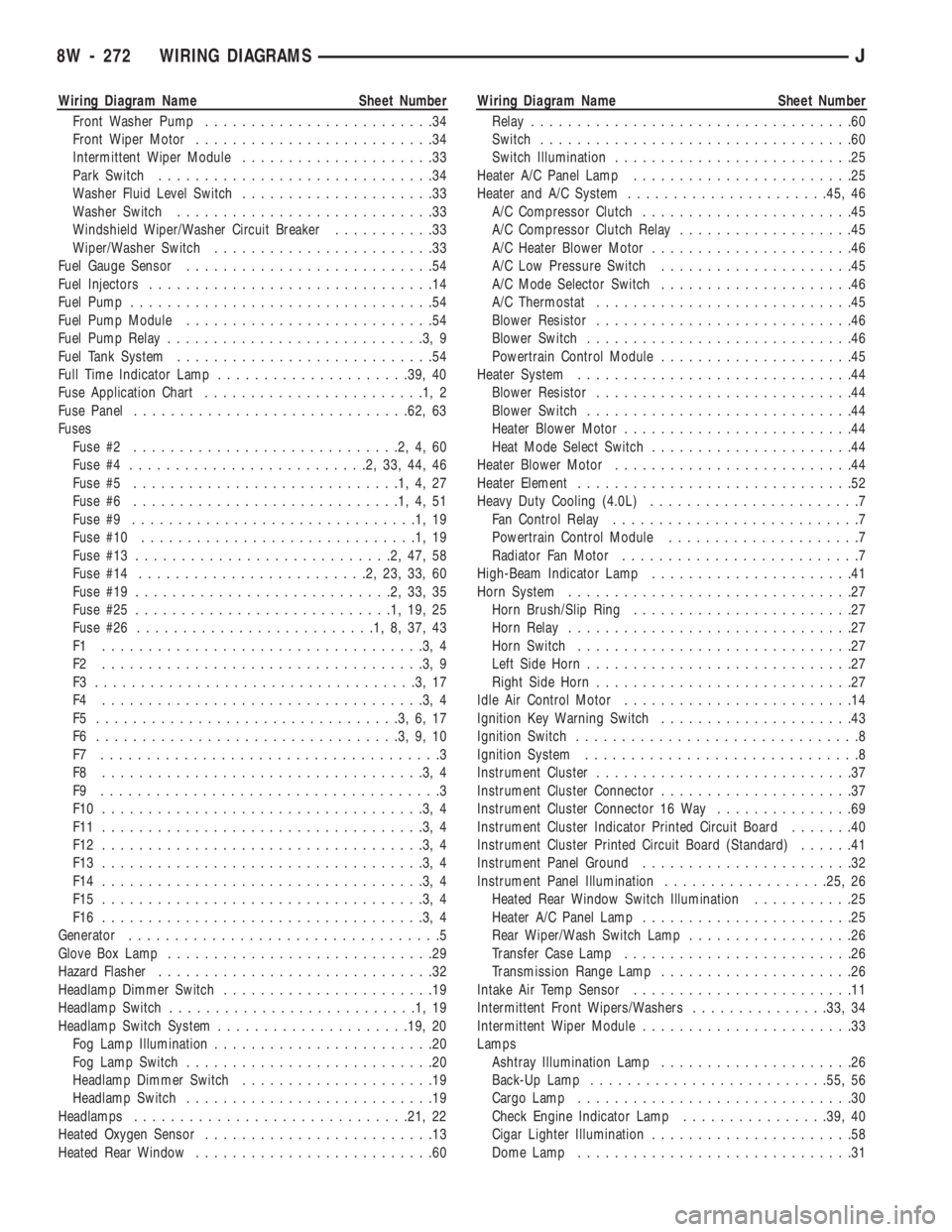
Wiring Diagram Name Sheet Number
Front Washer Pump.........................34
Front Wiper Motor..........................34
Intermittent Wiper Module.....................33
Park Switch..............................34
Washer Fluid Level Switch.....................33
Washer Switch............................33
Windshield Wiper/Washer Circuit Breaker...........33
Wiper/Washer Switch........................33
Fuel Gauge Sensor...........................54
Fuel Injectors...............................14
Fuel Pump.................................54
Fuel Pump Module...........................54
Fuel Pump Relay............................3,9
Fuel Tank System............................54
Full Time Indicator Lamp.....................39, 40
Fuse Application Chart........................1,2
Fuse Panel..............................62, 63
Fuses
Fuse #2.............................2,4,60
Fuse #4..........................2,33,44,46
Fuse #5.............................1,4,27
Fuse #6.............................1,4,51
Fuse #9...............................1,19
Fuse #10..............................1,19
Fuse #13............................2,47,58
Fuse #14.........................2,23,33,60
Fuse #19............................2,33,35
Fuse #25............................1,19,25
Fuse #26..........................1,8,37,43
F1 ...................................3,4
F2 ...................................3,9
F3 ...................................3,17
F4 ...................................3,4
F5 .................................3,6,17
F6 .................................3,9,10
F7 .....................................3
F8 ...................................3,4
F9 .....................................3
F10 ...................................3,4
F11 ...................................3,4
F12 ...................................3,4
F13 ...................................3,4
F14 ...................................3,4
F15 ...................................3,4
F16 ...................................3,4
Generator..................................5
Glove Box Lamp.............................29
Hazard Flasher..............................32
Headlamp Dimmer Switch.......................19
Headlamp Switch...........................1,19
Headlamp Switch System.....................19, 20
Fog Lamp Illumination........................20
Fog Lamp Switch...........................20
Headlamp Dimmer Switch.....................19
Headlamp Switch...........................19
Headlamps..............................21, 22
Heated Oxygen Sensor.........................13
Heated Rear Window..........................60Wiring Diagram Name Sheet Number
Relay...................................60
Switch..................................60
Switch Illumination..........................25
Heater A/C Panel Lamp........................25
Heater and A/C System......................45, 46
A/C Compressor Clutch.......................45
A/C Compressor Clutch Relay...................45
A/C Heater Blower Motor......................46
A/C Low Pressure Switch.....................45
A/C Mode Selector Switch.....................46
A/C Thermostat............................45
Blower Resistor............................46
Blower Switch.............................46
Powertrain Control Module.....................45
Heater System..............................44
Blower Resistor............................44
Blower Switch.............................44
Heater Blower Motor.........................44
Heat Mode Select Switch......................44
Heater Blower Motor..........................44
Heater Element..............................52
Heavy Duty Cooling (4.0L).......................7
Fan Control Relay...........................7
Powertrain Control Module.....................7
Radiator Fan Motor..........................7
High-Beam Indicator Lamp......................41
Horn System...............................27
Horn Brush/Slip Ring........................27
Horn Relay...............................27
Horn Switch..............................27
Left Side Horn.............................27
Right Side Horn............................27
Idle Air Control Motor.........................14
Ignition Key Warning Switch.....................43
Ignition Switch...............................8
Ignition System..............................8
Instrument Cluster............................37
Instrument Cluster Connector.....................37
Instrument Cluster Connector 16 Way...............69
Instrument Cluster Indicator Printed Circuit Board.......40
Instrument Cluster Printed Circuit Board (Standard)......41
Instrument Panel Ground.......................32
Instrument Panel Illumination..................25, 26
Heated Rear Window Switch Illumination...........25
Heater A/C Panel Lamp.......................25
Rear Wiper/Wash Switch Lamp..................26
Transfer Case Lamp.........................26
Transmission Range Lamp.....................26
Intake Air Temp Sensor........................11
Intermittent Front Wipers/Washers...............33, 34
Intermittent Wiper Module.......................33
Lamps
Ashtray Illumination Lamp.....................26
Back-Up Lamp..........................55, 56
Cargo Lamp..............................30
Check Engine Indicator Lamp................39, 40
Cigar Lighter Illumination......................58
Dome Lamp..............................31
8W - 272 WIRING DIAGRAMSJ
Page 768 of 1784
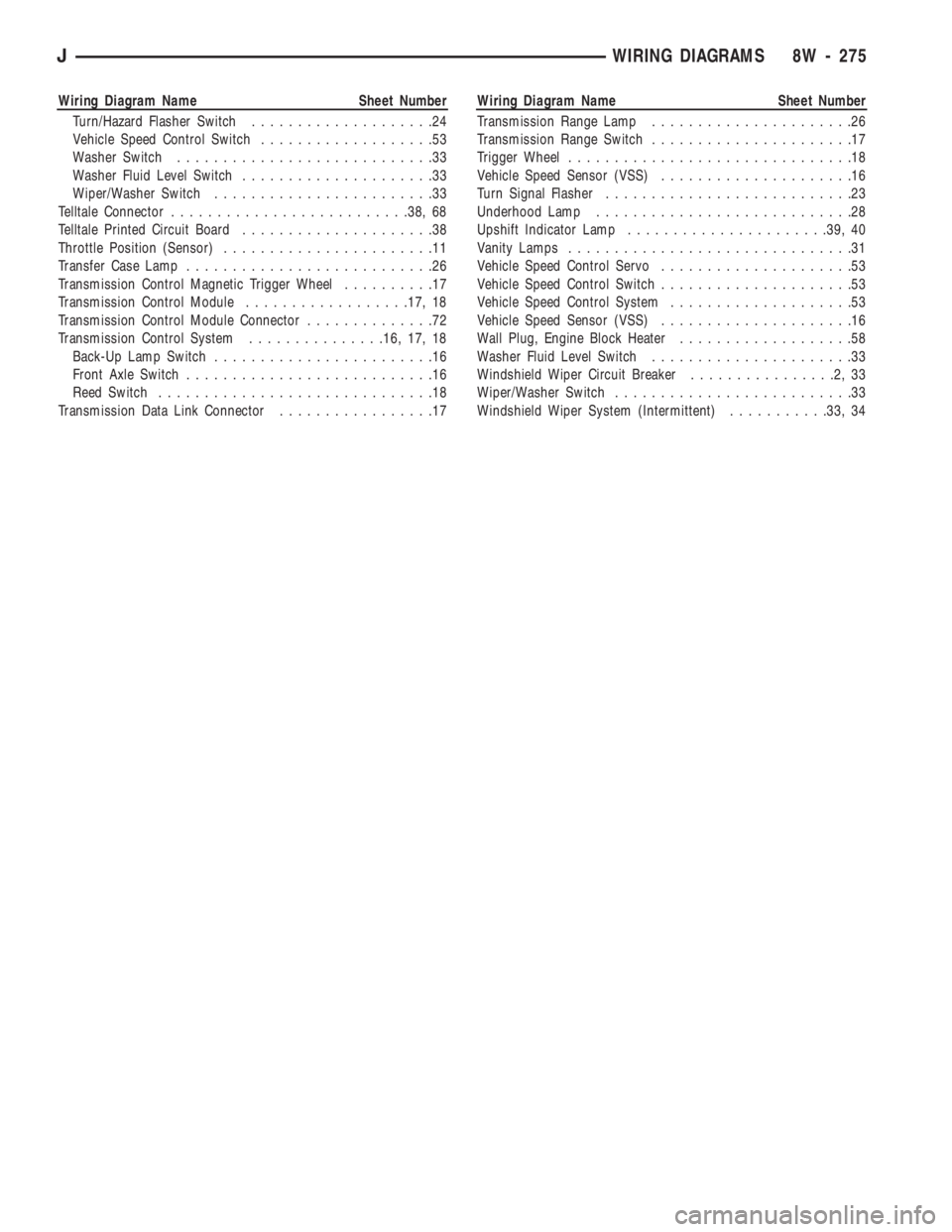
Wiring Diagram Name Sheet Number
Turn/Hazard Flasher Switch....................24
Vehicle Speed Control Switch...................53
Washer Switch............................33
Washer Fluid Level Switch.....................33
Wiper/Washer Switch........................33
Telltale Connector..........................38, 68
Telltale Printed Circuit Board.....................38
Throttle Position (Sensor).......................11
Transfer Case Lamp...........................26
Transmission Control Magnetic Trigger Wheel..........17
Transmission Control Module..................17, 18
Transmission Control Module Connector..............72
Transmission Control System...............16, 17, 18
Back-Up Lamp Switch........................16
Front Axle Switch...........................16
Reed Switch..............................18
Transmission Data Link Connector.................17Wiring Diagram Name Sheet Number
Transmission Range Lamp......................26
Transmission Range Switch......................17
Trigger Wheel...............................18
Vehicle Speed Sensor (VSS).....................16
Turn Signal Flasher...........................23
Underhood Lamp............................28
Upshift Indicator Lamp......................39, 40
Vanity Lamps...............................31
Vehicle Speed Control Servo.....................53
Vehicle Speed Control Switch.....................53
Vehicle Speed Control System....................53
Vehicle Speed Sensor (VSS).....................16
Wall Plug, Engine Block Heater...................58
Washer Fluid Level Switch......................33
Windshield Wiper Circuit Breaker................2,33
Wiper/Washer Switch..........................33
Windshield Wiper System (Intermittent)...........33, 34
JWIRING DIAGRAMS 8W - 275
Page 912 of 1784
(18) Check the ignition timing and adjust as nec-
essary.
(19) Install the grille and bumper, if removed.
(20) Connect negative cable to battery.
CAMSHAFT PIN REPLACEMENT
REMOVAL
WARNING: DO NOT LOOSEN THE RADIATOR
DRAIN COCK WITH THE SYSTEM HOT AND PRES-
SURIZED BECAUSE SERIOUS BURNS FROM COOL-
ANT CAN OCCUR.
(1) Disconnect negative cable from battery.
(2) Drain the radiator. DO NOT waste reusable
coolant. Drain the coolant into a clean container.
(3) Remove the fan and shroud.
(4) Disconnect the radiator overflow tube, radiator
hoses, automatic transmission fluid cooler pipes (if
equipped).
(5) Remove the radiator.
(6) If equipped with air conditioning:
CAUTION: DO NOT loosen or disconnect any air
conditioner system fittings. Move the condenser
and receiver/drier aside as a complete assembly.
(a) Remove the A/C compressor serpentine drive
belt idler pulley.
(b) Disconnect and remove the generator.
(c) Remove the A/C condenser attaching bolts
and move the condenser and receiver/drier assem-
bly up and out of the way.
(7) Remove the serpentine drive belt.
(8) Remove the crankshaft vibration damper.
(9) Remove the timing case cover. Clean the gas-
ket material from the cover.
(10) Remove the thrust pin and tension spring
from the preload bolt head.
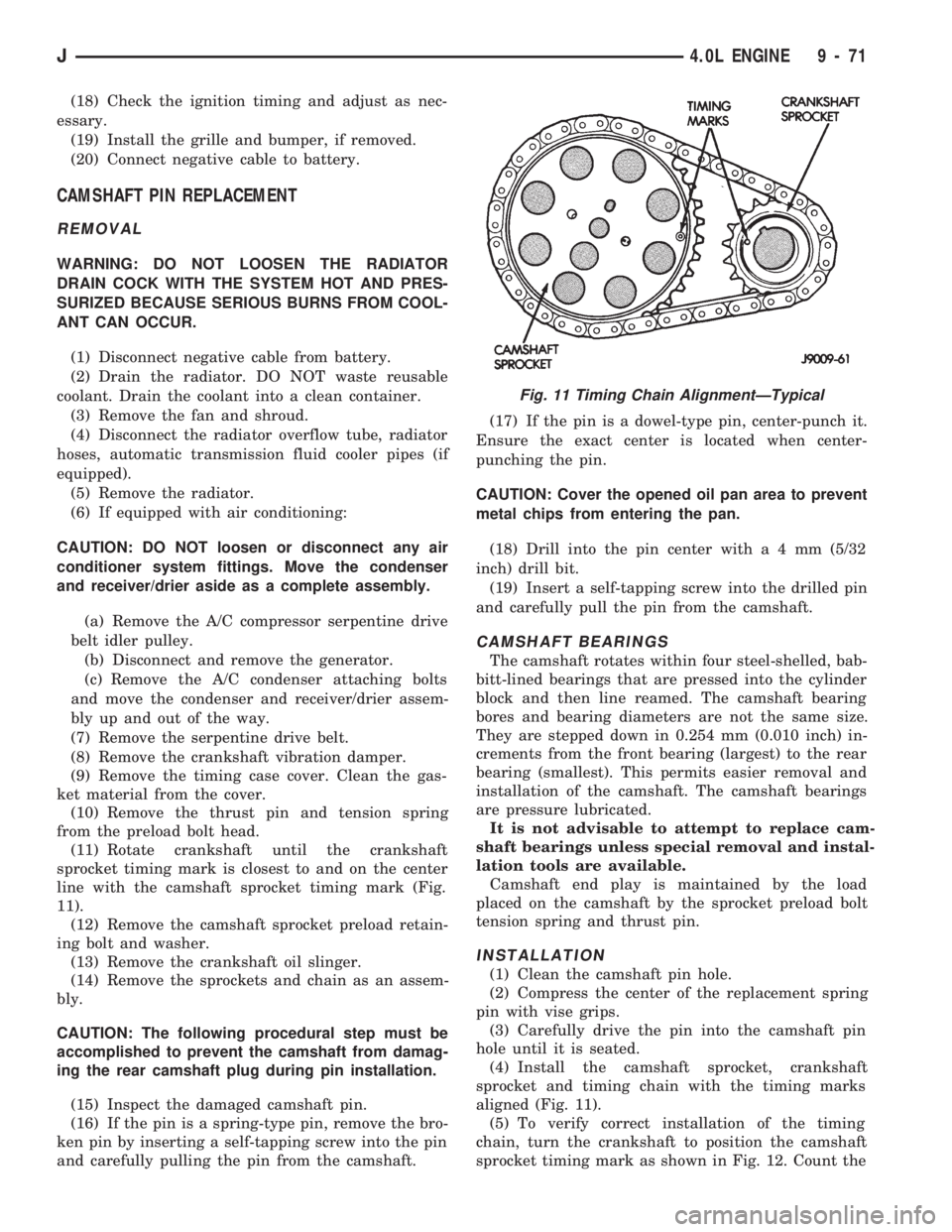
(11) Rotate crankshaft until the crankshaft
sprocket timing mark is closest to and on the center
line with the camshaft sprocket timing mark (Fig.
11).
(12) Remove the camshaft sprocket preload retain-
ing bolt and washer.
(13) Remove the crankshaft oil slinger.
(14) Remove the sprockets and chain as an assem-
bly.
CAUTION: The following procedural step must be
accomplished to prevent the camshaft from damag-
ing the rear camshaft plug during pin installation.
(15) Inspect the damaged camshaft pin.
(16) If the pin is a spring-type pin, remove the bro-
ken pin by inserting a self-tapping screw into the pin
and carefully pulling the pin from the camshaft.(17) If the pin is a dowel-type pin, center-punch it.
Ensure the exact center is located when center-
punching the pin.
CAUTION: Cover the opened oil pan area to prevent
metal chips from entering the pan.
(18) Drill into the pin center witha4mm(5/32
inch) drill bit.
(19) Insert a self-tapping screw into the drilled pin
and carefully pull the pin from the camshaft.
CAMSHAFT BEARINGS
The camshaft rotates within four steel-shelled, bab-
bitt-lined bearings that are pressed into the cylinder
block and then line reamed. The camshaft bearing
bores and bearing diameters are not the same size.
They are stepped down in 0.254 mm (0.010 inch) in-
crements from the front bearing (largest) to the rear
bearing (smallest). This permits easier removal and
installation of the camshaft. The camshaft bearings
are pressure lubricated.
It is not advisable to attempt to replace cam-
shaft bearings unless special removal and instal-
lation tools are available.
Camshaft end play is maintained by the load
placed on the camshaft by the sprocket preload bolt
tension spring and thrust pin.
INSTALLATION
(1) Clean the camshaft pin hole.
(2) Compress the center of the replacement spring
pin with vise grips.
(3) Carefully drive the pin into the camshaft pin
hole until it is seated.
(4) Install the camshaft sprocket, crankshaft
sprocket and timing chain with the timing marks
aligned (Fig. 11).
(5) To verify correct installation of the timing
chain, turn the crankshaft to position the camshaft
sprocket timing mark as shown in Fig. 12. Count the
Fig. 11 Timing Chain AlignmentÐTypical
J4.0L ENGINE 9 - 71