Page 1428 of 1784
(72) Apply 3 mm (1/8 in.) wide bead of Mopar gas-
ket maker, silicone adhesive sealer, or Loctite 518 to
seal surface of extension housing.
(73) Install extension housing on case. Tighten
housing bolts to 41 Nzm (30 ft. lbs.) torque.
(74) Install front yoke. Secure yoke with new seal
washer and nut. Tighten nut to 149 Nzm (110 ft. lbs.)
torque.
(75) Install new gasket on vacuum switch and in-
stall switch in the case. Tighten switch to 27 Nzm (20
ft. lbs.) torque.
(76) Install speedometer components (Fig. 85).
(77) Install and tighten drain plug to 47 Nzm (35
ft. lbs.) torque.
(78) After installing transfer case, refill with rec-
ommended transmission fluid.
(79) Tighten fill plug to 47 Nzm (35 ft. lbs.) torque.
(80) Adjust transfer case shift linkage.
Fig. 85 Speedometer Components
JNP242 TRANSFER CASE 21 - 317
Page 1467 of 1784
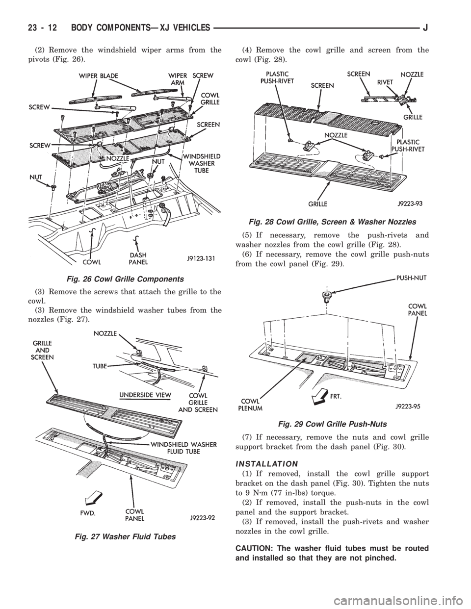
(2) Remove the windshield wiper arms from the
pivots (Fig. 26).
(3) Remove the screws that attach the grille to the
cowl.
(3) Remove the windshield washer tubes from the
nozzles (Fig. 27).(4) Remove the cowl grille and screen from the
cowl (Fig. 28).
(5) If necessary, remove the push-rivets and
washer nozzles from the cowl grille (Fig. 28).
(6) If necessary, remove the cowl grille push-nuts
from the cowl panel (Fig. 29).
(7) If necessary, remove the nuts and cowl grille
support bracket from the dash panel (Fig. 30).
INSTALLATION
(1) If removed, install the cowl grille support
bracket on the dash panel (Fig. 30). Tighten the nuts
to9Nzm (77 in-lbs) torque.
(2) If removed, install the push-nuts in the cowl
panel and the support bracket.
(3) If removed, install the push-rivets and washer
nozzles in the cowl grille.
CAUTION: The washer fluid tubes must be routed
and installed so that they are not pinched.
Fig. 26 Cowl Grille Components
Fig. 27 Washer Fluid Tubes
Fig. 28 Cowl Grille, Screen & Washer Nozzles
Fig. 29 Cowl Grille Push-Nuts
23 - 12 BODY COMPONENTSÐXJ VEHICLESJ
Page 1470 of 1784
²remove the vapor canister from the fender inner
panel (Figs. 42 and 45);
²remove the A/C Receiver/Drier from the fender in-
ner panel (Fig. 40); and
²if equipped, remove the Daytime Running Light
(DRL) module from the fender inner panel (Fig. 46).
²support the hood and remove the hood support rod
from the fender inner panel.
(3) Remove the hood bumper from the fender inner
panel (Fig. 47).
(4) Raise and support the vehicle.
(5) Remove the front wheel.
(6) Remove the fender liner, fender flare and re-
tainers (Fig. 48):
²remove the screws that attach the lower part of
Fig. 41 Hood Ajar Switch Removal/Installation
Fig. 42 Power Distribution Center and Vapor Canister
Fig. 43 Coolant Recovery Bottle
Fig. 39 Coolant Recovery Bottle, Windshield Washer
Fluid Reservoir & Hood Support Rod
Fig. 40 Hood Ajar Switch, Speed Servo & A/C
Receiver/Drier
JBODY COMPONENTSÐXJ VEHICLES 23 - 15
Page 1473 of 1784
(15) Right fender only: install the A/C Receiver/
Drier on the fender inner panel.
(16) Right fender only: install the vapor canister
on the fender inner panel. Tighten the vapor canister
screws to 5 Nzm (45 in-lbs) torque.
(17) Right fender only: install the PDC, coolant recov-
ery bottle and speed servo on the fender inner panel.
(18) Right fender only: install the hood ajar switch,
if equipped. Tighten the screws to 2 Nzm (15 in-lbs)
torque.
(19) Right fender only: install the windshield
washer fluid reservoir on the inner panel (Fig. 39).
(20) Right fender only: install the battery tray and
battery on the inner panel.
(21) Right fender only: if equipped, install the ra-
dio antenna. Tighten the nut/escutcheon to 4.5 Nzm
(40 in-lbs) torque. Tighten the power antenna bracket
screws to 2 Nzm (20 in-lbs) torque.
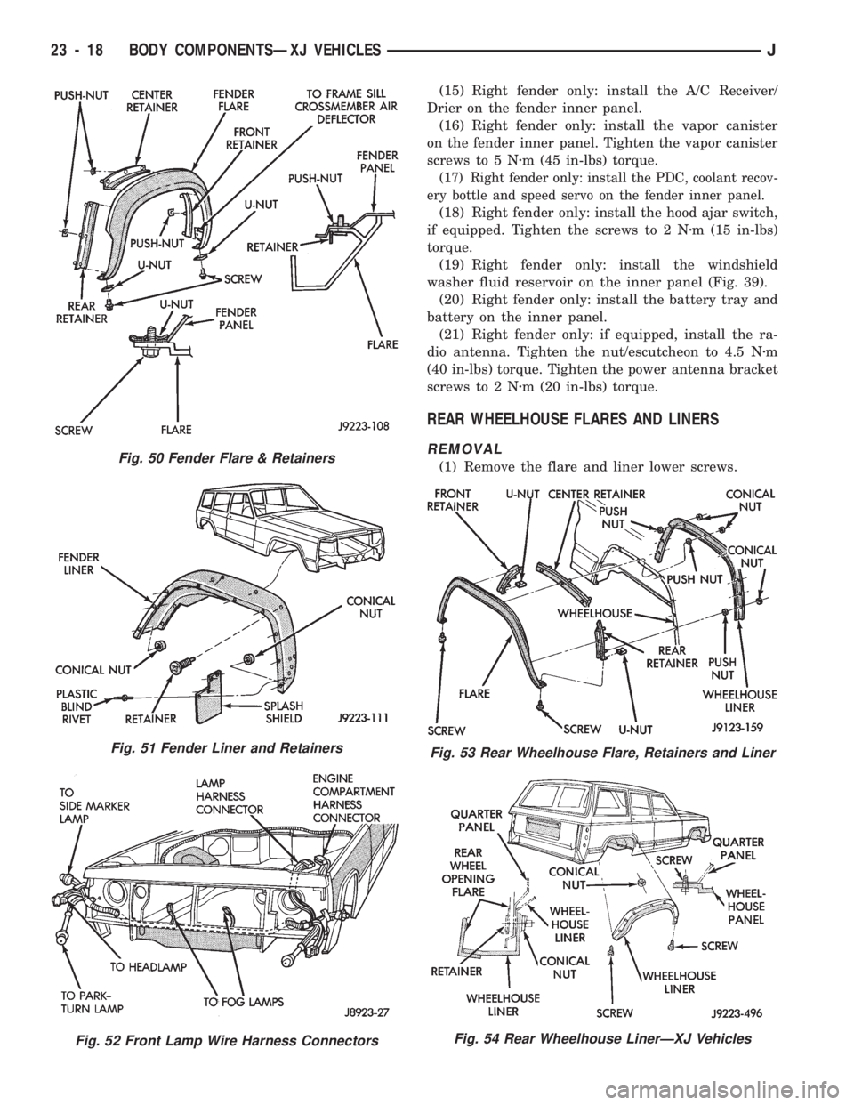
REAR WHEELHOUSE FLARES AND LINERS
REMOVAL
(1) Remove the flare and liner lower screws.Fig. 50 Fender Flare & Retainers
Fig. 51 Fender Liner and Retainers
Fig. 52 Front Lamp Wire Harness Connectors
Fig. 53 Rear Wheelhouse Flare, Retainers and Liner
Fig. 54 Rear Wheelhouse LinerÐXJ Vehicles
23 - 18 BODY COMPONENTSÐXJ VEHICLESJ
Page 1591 of 1784
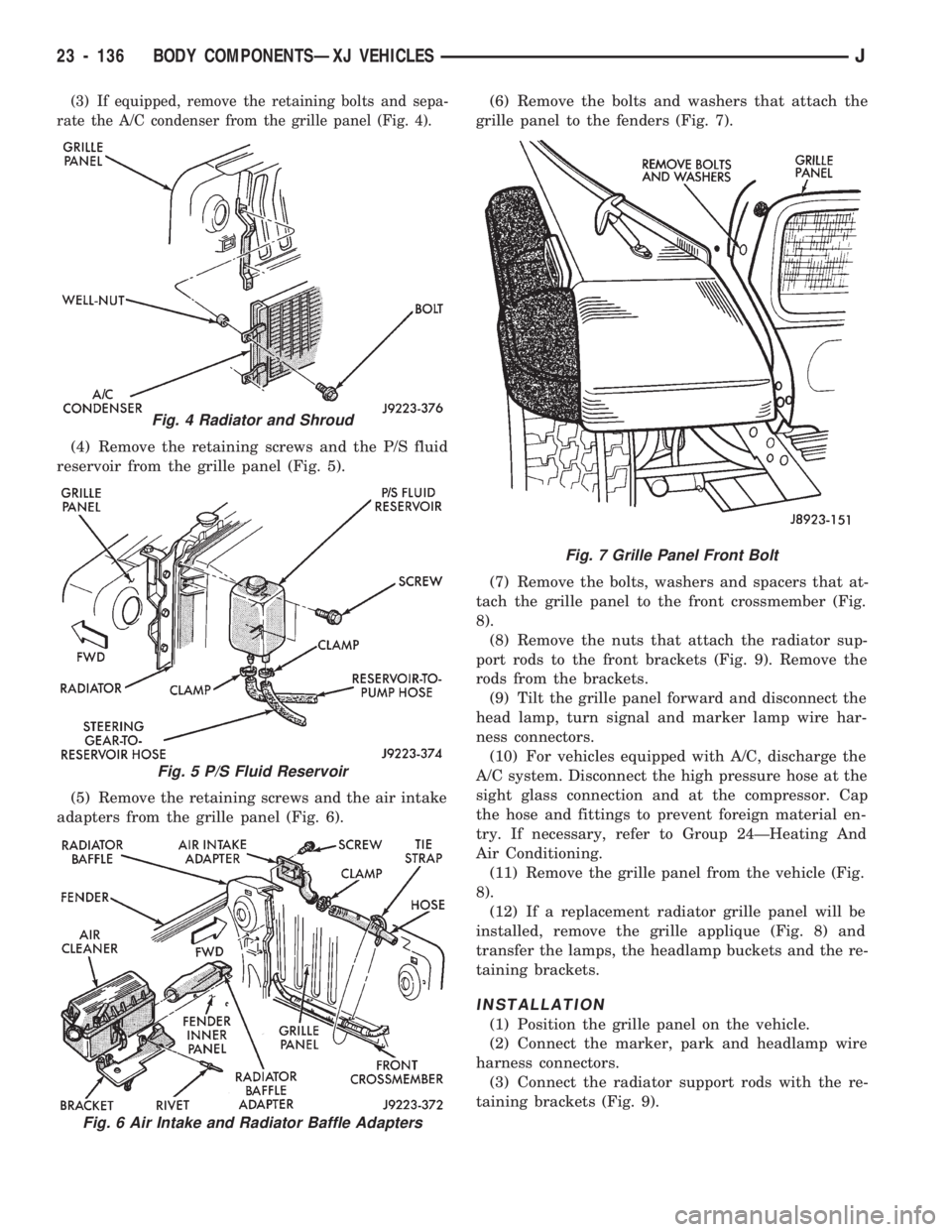
(3) If equipped, remove the retaining bolts and sepa-
rate the A/C condenser from the grille panel (Fig. 4).
(4) Remove the retaining screws and the P/S fluid
reservoir from the grille panel (Fig. 5).
(5) Remove the retaining screws and the air intake
adapters from the grille panel (Fig. 6).(6) Remove the bolts and washers that attach the
grille panel to the fenders (Fig. 7).
(7) Remove the bolts, washers and spacers that at-
tach the grille panel to the front crossmember (Fig.
8).
(8) Remove the nuts that attach the radiator sup-
port rods to the front brackets (Fig. 9). Remove the
rods from the brackets.
(9) Tilt the grille panel forward and disconnect the
head lamp, turn signal and marker lamp wire har-
ness connectors.
(10) For vehicles equipped with A/C, discharge the
A/C system. Disconnect the high pressure hose at the
sight glass connection and at the compressor. Cap
the hose and fittings to prevent foreign material en-
try. If necessary, refer to Group 24ÐHeating And
Air Conditioning.
(11) Remove the grille panel from the vehicle (Fig.
8).
(12) If a replacement radiator grille panel will be
installed, remove the grille applique (Fig. 8) and
transfer the lamps, the headlamp buckets and the re-
taining brackets.
INSTALLATION
(1) Position the grille panel on the vehicle.
(2) Connect the marker, park and headlamp wire
harness connectors.
(3) Connect the radiator support rods with the re-
taining brackets (Fig. 9).
Fig. 4 Radiator and Shroud
Fig. 5 P/S Fluid Reservoir
Fig. 6 Air Intake and Radiator Baffle Adapters
Fig. 7 Grille Panel Front Bolt
23 - 136 BODY COMPONENTSÐXJ VEHICLESJ
Page 1597 of 1784
²remove the horn from the fender inner panel (Fig.
24); and
²remove the windshield washer fluid reservoir and
coolant reserve bottle from the fender inner panel
(Figs. 25 and 26).(4) Right fender:
²remove the jack and related tools from the jack
storage tray (Fig. 27);
Fig. 23 Air Cleaner Housing and Support Bracket
Fig. 24 Horn Removal/Installation
Fig. 25 Windshield Washer Fluid Reservoir
Fig. 26 Coolant Reserve Bottle
Fig. 27 Jack and Related Tools
23 - 142 BODY COMPONENTSÐXJ VEHICLESJ
Page 1599 of 1784
INSTALLATION
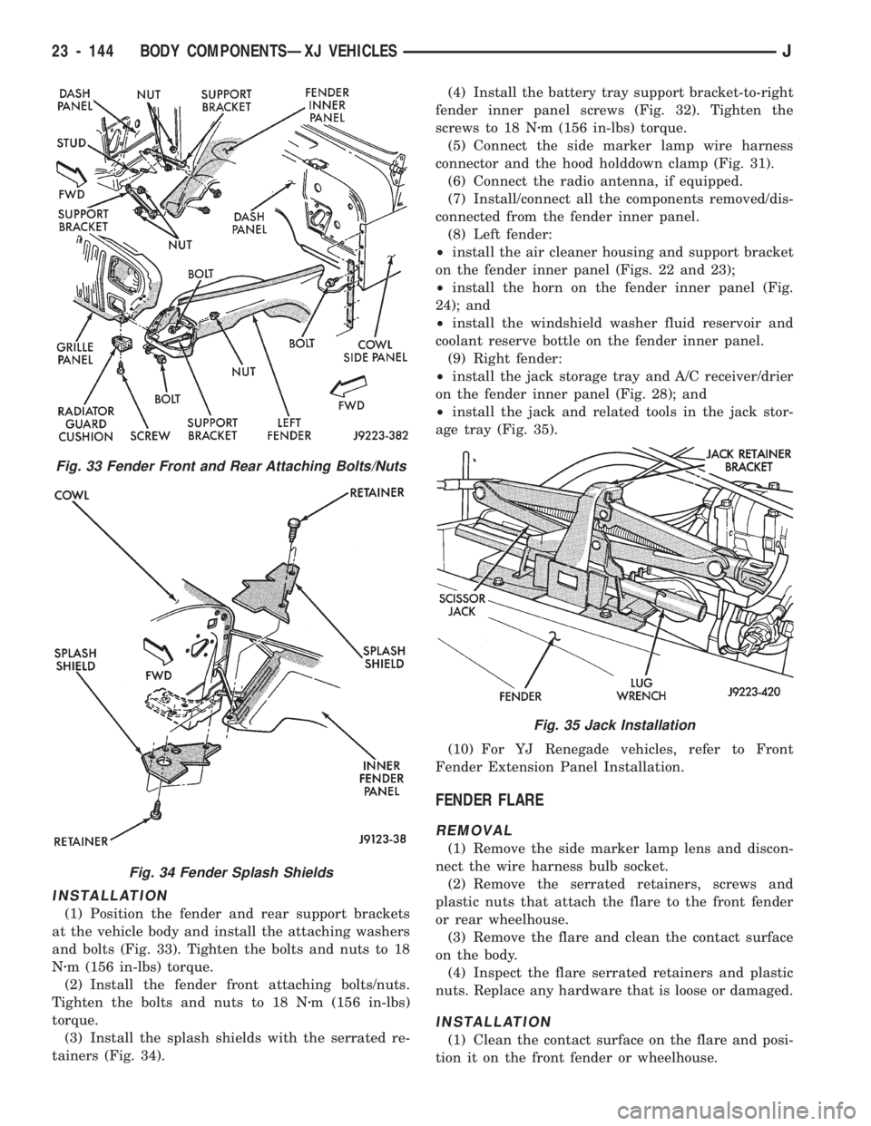
(1) Position the fender and rear support brackets
at the vehicle body and install the attaching washers
and bolts (Fig. 33). Tighten the bolts and nuts to 18
Nzm (156 in-lbs) torque.
(2) Install the fender front attaching bolts/nuts.
Tighten the bolts and nuts to 18 Nzm (156 in-lbs)
torque.
(3) Install the splash shields with the serrated re-
tainers (Fig. 34).(4) Install the battery tray support bracket-to-right
fender inner panel screws (Fig. 32). Tighten the
screws to 18 Nzm (156 in-lbs) torque.
(5) Connect the side marker lamp wire harness
connector and the hood holddown clamp (Fig. 31).
(6) Connect the radio antenna, if equipped.
(7) Install/connect all the components removed/dis-
connected from the fender inner panel.
(8) Left fender:
²install the air cleaner housing and support bracket
on the fender inner panel (Figs. 22 and 23);
²install the horn on the fender inner panel (Fig.
24); and
²install the windshield washer fluid reservoir and
coolant reserve bottle on the fender inner panel.
(9) Right fender:
²install the jack storage tray and A/C receiver/drier
on the fender inner panel (Fig. 28); and
²install the jack and related tools in the jack stor-
age tray (Fig. 35).
(10) For YJ Renegade vehicles, refer to Front
Fender Extension Panel Installation.
FENDER FLARE
REMOVAL
(1) Remove the side marker lamp lens and discon-
nect the wire harness bulb socket.
(2) Remove the serrated retainers, screws and
plastic nuts that attach the flare to the front fender
or rear wheelhouse.
(3) Remove the flare and clean the contact surface
on the body.
(4) Inspect the flare serrated retainers and plastic
nuts. Replace any hardware that is loose or damaged.
INSTALLATION
(1) Clean the contact surface on the flare and posi-
tion it on the front fender or wheelhouse.
Fig. 33 Fender Front and Rear Attaching Bolts/Nuts
Fig. 34 Fender Splash Shields
Fig. 35 Jack Installation
23 - 144 BODY COMPONENTSÐXJ VEHICLESJ
Page 1617 of 1784
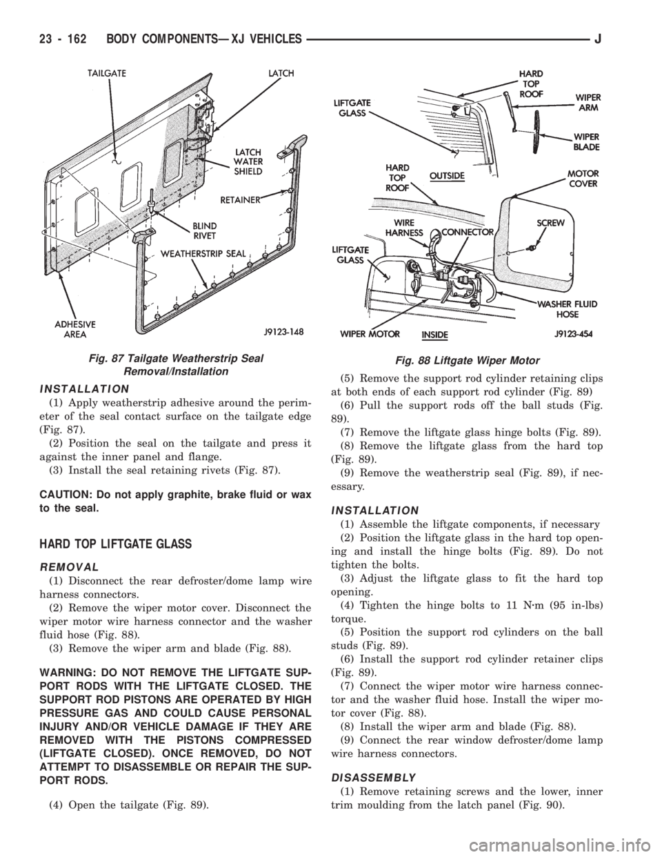
INSTALLATION
(1) Apply weatherstrip adhesive around the perim-
eter of the seal contact surface on the tailgate edge
(Fig. 87).
(2) Position the seal on the tailgate and press it
against the inner panel and flange.
(3) Install the seal retaining rivets (Fig. 87).
CAUTION: Do not apply graphite, brake fluid or wax
to the seal.
HARD TOP LIFTGATE GLASS
REMOVAL
(1) Disconnect the rear defroster/dome lamp wire
harness connectors.
(2) Remove the wiper motor cover. Disconnect the
wiper motor wire harness connector and the washer
fluid hose (Fig. 88).
(3) Remove the wiper arm and blade (Fig. 88).
WARNING: DO NOT REMOVE THE LIFTGATE SUP-
PORT RODS WITH THE LIFTGATE CLOSED. THE
SUPPORT ROD PISTONS ARE OPERATED BY HIGH
PRESSURE GAS AND COULD CAUSE PERSONAL
INJURY AND/OR VEHICLE DAMAGE IF THEY ARE
REMOVED WITH THE PISTONS COMPRESSED
(LIFTGATE CLOSED). ONCE REMOVED, DO NOT
ATTEMPT TO DISASSEMBLE OR REPAIR THE SUP-
PORT RODS.
(4) Open the tailgate (Fig. 89).(5) Remove the support rod cylinder retaining clips
at both ends of each support rod cylinder (Fig. 89)
(6) Pull the support rods off the ball studs (Fig.
89).
(7) Remove the liftgate glass hinge bolts (Fig. 89).
(8) Remove the liftgate glass from the hard top
(Fig. 89).
(9) Remove the weatherstrip seal (Fig. 89), if nec-
essary.
INSTALLATION
(1) Assemble the liftgate components, if necessary
(2) Position the liftgate glass in the hard top open-
ing and install the hinge bolts (Fig. 89). Do not
tighten the bolts.
(3) Adjust the liftgate glass to fit the hard top
opening.
(4) Tighten the hinge bolts to 11 Nzm (95 in-lbs)
torque.
(5) Position the support rod cylinders on the ball
studs (Fig. 89).
(6) Install the support rod cylinder retainer clips
(Fig. 89).
(7) Connect the wiper motor wire harness connec-
tor and the washer fluid hose. Install the wiper mo-
tor cover (Fig. 88).
(8) Install the wiper arm and blade (Fig. 88).
(9) Connect the rear window defroster/dome lamp
wire harness connectors.
DISASSEMBLY
(1) Remove retaining screws and the lower, inner
trim moulding from the latch panel (Fig. 90).
Fig. 87 Tailgate Weatherstrip Seal
Removal/InstallationFig. 88 Liftgate Wiper Motor
23 - 162 BODY COMPONENTSÐXJ VEHICLESJ