1994 JEEP CHEROKEE tow
[x] Cancel search: towPage 201 of 1784
(5) Mark or tag HCU hydraulic lines for assembly
reference.
(6) Disconnect hydraulic lines at HCU.
(7) Move HCU harness and air cleaner hose pipe
aside for access to HCU bracket nuts.
(8) Remove single bolt and two nuts attaching
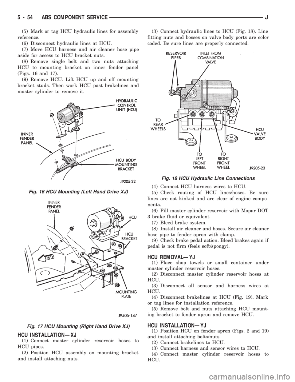
HCU to mounting bracket on inner fender panel
(Figs. 16 and 17).
(9) Remove HCU. Lift HCU up and off mounting
bracket studs. Then work HCU past brakelines and
master cylinder to remove it.
HCU INSTALLATIONÐXJ
(1) Connect master cylinder reservoir hoses to
HCU pipes.
(2) Position HCU assembly on mounting bracket
and install attaching nuts.(3) Connect hydraulic lines to HCU (Fig. 18). Line
fitting nuts and bosses on valve body ports are color
coded. Be sure lines are properly connected.
(4) Connect HCU harness wires to HCU.
(5) Check routing of HCU lines/hoses. Be sure
lines are not kinked and are clear of engine compo-
nents.
(6) Fill master cylinder reservoir with Mopar DOT
3 brake fluid or equivalent.
(7) Bleed brake system.
(8) Install air cleaner and hoses. Secure air cleaner
hose pipe to fender apron with clamp.
(9) Check brake pedal action. Bleed brakes again if
pedal is not firm (feels soft/spongy).
HCU REMOVALÐYJ
(1) Place shop towels or small container under
master cylinder reservoir hoses.
(2) Disconnect master cylinder reservoir hoses at
HCU.
(3) Disconnect all sensor and harness wires at
HCU.
(4) Disconnect brakelines at HCU (Fig. 19). Mark
or tag lines for installation reference.
(5) Remove bolt and nuts attaching HCU mount-
ing bracket to fender apron and remove HCU.
HCU INSTALLATIONÐYJ
(1) Position HCU on fender apron (Figs. 2 and 19)
and install attaching bolts/nuts.
(2) Connect brakelines to HCU.
(3) Connect harness and sensor wires to HCU.
(4) Connect master cylinder reservoir hoses to
HCU.
Fig. 16 HCU Mounting (Left Hand Drive XJ)
Fig. 17 HCU Mounting (Right Hand Drive XJ)
Fig. 18 HCU Hydraulic Line Connections
5 - 54 ABS COMPONENT SERVICEJ
Page 217 of 1784
²input shaft pilot hub
²transmission front bearing retainer slide surface
Never apply grease to any part of the clutch
cover, or disc.
RECOMMENDED LUBRICANTS
Use Mopar multi-purpose grease for the clutch
pedal bushings and pivot shaft. Use Mopar high tem-
perature grease (or equivalent) for all other lubrica-
tion requirements. Apply recommended amounts and
do not overlubricate.
CLUTCH OPERATION
Leverage, spring force and friction are what make
the clutch work. The disc serves as the friction ele-
ment. The diaphragm spring acting on the pressure
plate provides the apply (or clamping) force. And the
pedal, hydraulic linkage, release lever and bearing
provide the leverage.
The clutch cover, which is bolted to the flywheel, is
the component that clamps the disc against the fly-
wheel. The cover is actually an assembly consisting
of the cover, diaphragm spring, pressure plate, and
fulcrum components.
It is the clutch cover pressure plate that actually
clamps the clutch disc against the flywheel. Pressure
plate force is supplied by the diaphragm spring.
The disc has a splined hub for installation on the
transmission input shaft splines. The splined hub is
what connects the disc to the transmission.The clutch linkage uses hydraulic pressure to oper-
ate the clutch. The clutch master cylinder is con-
nected to the clutch pedal and the slave cylinder is
connected to the release lever. In operation, pressing
the clutch pedal develops fluid pressure in the clutch
master cylinder. This pressure is then transmitted
directly to the slave cylinder via the connecting line.
In turn, the slave cylinder operates the clutch release
lever.
The clutch release bearing is mounted on the
transmission front bearing retainer. The bearing is
attached to the release lever which moves the bear-
ing in and out of contact with the diaphragm spring.
In operation, slave cylinder force causes the release
lever to pivot toward the clutch. This action moves
the release bearing into direct contact with the dia-
phragm spring fingers. As additional force is applied,
the release bearing pushes the spring fingers inward
relieving spring force on the pressure plate. At this
point, the clutch disc is disengaged and freewheeling.
The process of clutch re-engagement, is simply the
reverse of what occurs during disengagement. Re-
leasing pedal pressure removes linkage pressure. The
release bearing moves away from the spring which
again applies clamping force on the disc through the
pressure plate.
6 - 2 CLUTCHJ
Page 225 of 1784
CLUTCH SERVICE
INDEX
page page
Clutch Cover and Disc Installation............ 10
Clutch Cover and Disc Removal............. 10
Clutch Fluid Level........................ 14
Clutch Housing Replacement................ 11
Clutch Hydraulic Linkage Installation.......... 12
Clutch Hydraulic Linkage Removal........... 11Clutch Pedal Installation................... 15
Clutch Pedal Removal..................... 15
Clutch Safety Precautions.................. 10
Flywheel Service......................... 15
Pilot Bearing Replacement................. 11
Release Bearing Replacement............... 11
CLUTCH SAFETY PRECAUTIONS
WARNING: EXERCISE CARE WHEN SERVICING
CLUTCH COMPONENTS. DUST AND DIRT ON
CLUTCH PARTS USE MAY CONTAIN ASBESTOS FI-
BERS. BREATHING EXCESSIVE CONCENTRATIONS
OF THESE FIBERS CAN CAUSE SERIOUS BODILY
HARM. WEAR A RESPIRATOR DURING SERVICE
AND NEVER CLEAN CLUTCH COMPONENTS WITH
COMPRESSED AIR OR WITH A DRY BRUSH. EI-
THER CLEAN THE COMPONENTS WITH A WATER
DAMPENED RAGS OR USE A VACUUM CLEANER
SPECIFICALLY DESIGNED FOR REMOVING ASBES-
TOS FIBERS AND DUST. DO NOT CREATE DUST
BY SANDING A CLUTCH DISC. REPLACE THE DISC
IF THE FRICTION MATERIAL IS DAMAGED OR
CONTAMINATED. DISPOSE OF ALL DUST AND
DIRT CONTAINING ASBESTOS FIBERS IN SEALED
BAGS OR CONTAINERS. THIS WILL HELP MINIMIZE
EXPOSURE TO YOURSELF AND TO OTHERS. FOL-
LOW ALL RECOMMENDED SAFETY PRACTICES
PRESCRIBED BY THE OCCUPATIONAL SAFETY
AND HEALTH ADMINISTRATION (OSHA) AND THE
ENVIRONMENTAL SAFETY AGENCY (EPA), FOR
THE HANDLING AND DISPOSAL OF PRODUCTS
CONTAINING ASBESTOS.
CLUTCH COVER AND DISC REMOVAL
(1) Remove transmission. Refer to procedures in
Group 21.
(2) If original clutch cover will be reinstalled,
mark position of cover on flywheel for assembly ref-
erence. Use paint or a scriber for this purpose.
(3) If clutch cover is to be replaced, cover bolts can
be removed in any sequence. However, if original
cover will be reinstalled, loosen cover bolts evenly
and in rotation to relieve spring tension equally.
This is necessary avoid warping cover.
(4) Remove cover bolts and remove cover and disc
(Fig. 2).
CLUTCH COVER AND DISC INSTALLATION
(1) Lightly scuff sand flywheel face with 180 grit
emery cloth. Then clean surface with a wax and
grease remover.
(2) Lubricate pilot bearing with Mopar high tem-
perature bearing grease.
(3) Check runout and free operation of new clutch
disc as follows:
(a) Slide disc onto transmission input shaft
splines. Disc should slide freely on splines.
(b) Leave disc on shaft and check face runout
with dial indicator. Check runout at disc hub and
about 6 mm (1/4 in.) from outer edge of facing.
(c) Face runout should not exceed 0.5 mm (0.020
in.). Obtain another clutch disc if runout exceeds
this limit.
(4) Position clutch disc on flywheel. Be sure side of
disc marked flywheel side is positioned against fly-
wheel (Fig. 2). If disc is not marked, be sure flat side
of disc hub is toward flywheel.
(5) Insert clutch alignment tool in clutch disc (Fig.
3).
(6) Insert alignment tool in pilot bearing and posi-
tion disc on flywheel. Be sure disc hub is positioned
correctly. Side of hub marked Flywheel Side should
face flywheel (Fig. 2). If disc is not marked, place flat
side of disc against flywheel.
(7) Position clutch cover over disc and on flywheel
(Fig. 3).
(8) Install clutch cover bolts finger tight.
(9) Tighten cover bolts evenly and in rotation a
few threads at a time.Cover bolts must be tight-
ened evenly and to specified torque to avoid dis-
torting cover. Tightening torques are 31 Nzm (23
ft. lbs.) on 2.5L engines and 54 Nzm (40 ft. lbs.) on
4.0L engines.
(10) Apply light coat of Mopar high temperature
bearing grease to pilot bearing hub and splines of
transmission input shaft.Do not overlubricate
shaft splines. This will result in grease contami-
nation of disc.
(11) Install transmission (Fig. 4). Refer to proce-
dures in Group 21.
6 - 10 CLUTCH SERVICEJ
Page 238 of 1784
ERASING TROUBLE CODES
After the problem has been repaired, the DRB scan
tool must be used to erase a DTC. Refer to the ap-
propriate Powertrain Diagnostic Procedures service
manual for operation of the DRB scan tool.
DRB SCAN TOOL
For operation of the DRB scan tool, refer to the ap-
propriate Powertrain Diagnostic Procedures service
manual.
PRELIMINARY CHECKS
ENGINE COOLING SYSTEM OVERHEATING
Establish what driving conditions caused the com-
plaint. Abnormal loads on the cooling system such as
the following may be the cause.
1. PROLONGED IDLE, VERY HIGH AMBI-
ENT TEMPERATURE, SLIGHT TAIL WIND AT
IDLE, SLOW TRAFFIC, TRAFFIC JAMS, HIGH
SPEED, OR STEEP GRADES:
Driving techniques that avoid overheating are:
²Idle with A/C off when temperature gauge is at
end of normal range.
²Increasing engine speed for more air flow is recom-
mended.2. TRAILER TOWING:
Consult Trailer Towing section of owners manual.
Do not exceed limits.
3. AIR CONDITIONING; ADD-ON OR AFTER
MARKET:
A maximum cooling package should have been or-
dered with vehicle if add-on or after market A/C is
installed. If not, maximum cooling system compo-
nents should be installed for model involved per
manufacturer's specifications.
4. RECENT SERVICE OR ACCIDENT RE-
PAIR:
Determine if any recent service has been performed
on vehicle that may effect cooling system. This may
be:
²Engine adjustments (incorrect timing)
²Slipping engine accessory drive belt(s)
²Brakes (possibly dragging)
²Changed parts (incorrect water pump rotating in
wrong direction)
²Reconditioned radiator or cooling system refilling
(possibly under-filled or air trapped in system).
If investigation reveals none of the above as a
cause for engine overheating complaint, refer to fol-
lowing Symptom and Action chart.
JCOOLING SYSTEM 7 - 5
Page 286 of 1784
IGNITION SWITCH TEST
After testing starter solenoid and relay and they
check out OK, trouble is probably with ignition
switch or its wiring.
Check all wiring for opens and shorts, and connec-
tions for being loose or corroded.
PARK/NEUTRAL POSITION SWITCH
Refer to Group 21 - Transmissions for diagnostic
information.
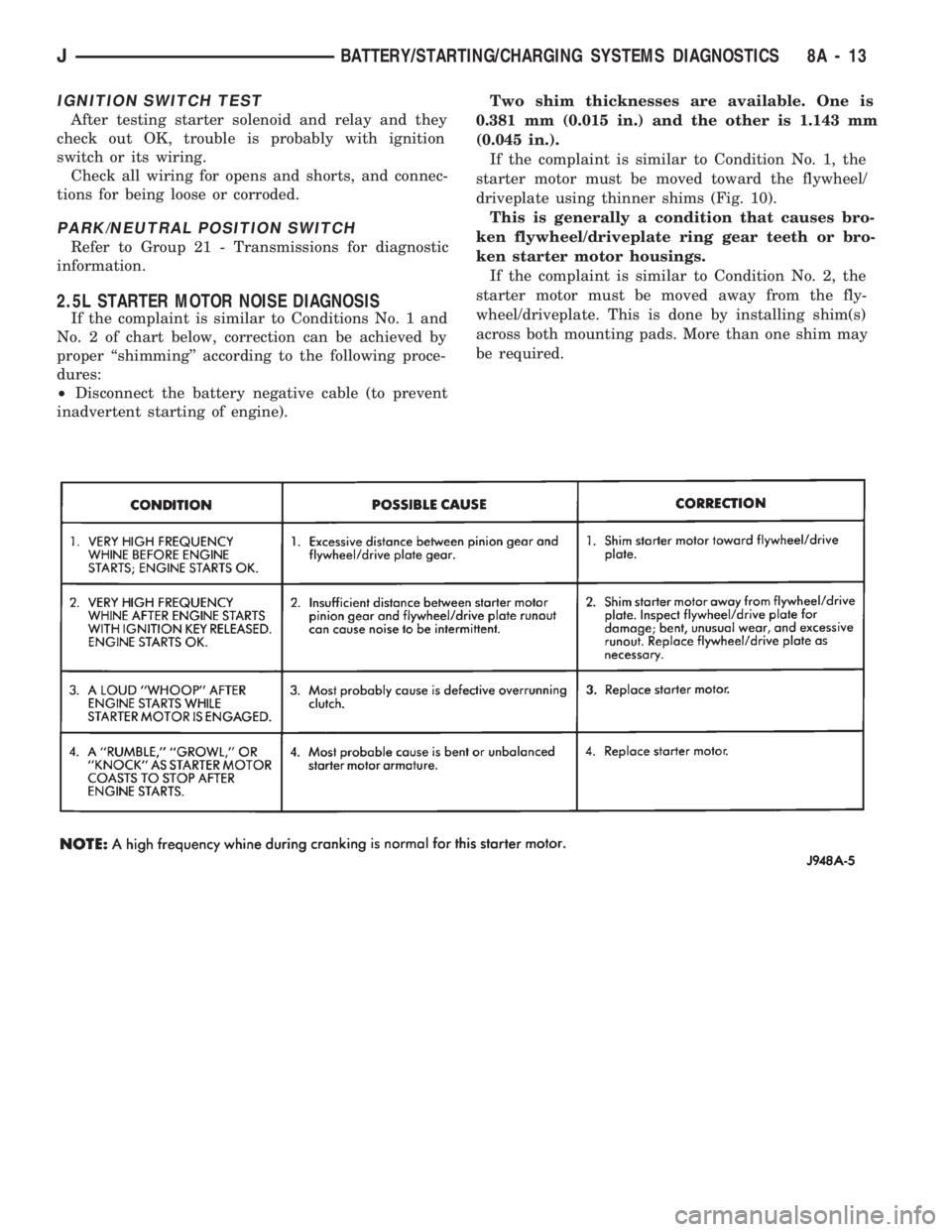
2.5L STARTER MOTOR NOISE DIAGNOSIS
If the complaint is similar to Conditions No. 1 and
No. 2 of chart below, correction can be achieved by
proper ``shimming'' according to the following proce-
dures:
²Disconnect the battery negative cable (to prevent
inadvertent starting of engine).Two shim thicknesses are available. One is
0.381 mm (0.015 in.) and the other is 1.143 mm
(0.045 in.).
If the complaint is similar to Condition No. 1, the
starter motor must be moved toward the flywheel/
driveplate using thinner shims (Fig. 10).
This is generally a condition that causes bro-
ken flywheel/driveplate ring gear teeth or bro-
ken starter motor housings.
If the complaint is similar to Condition No. 2, the
starter motor must be moved away from the fly-
wheel/driveplate. This is done by installing shim(s)
across both mounting pads. More than one shim may
be required.
JBATTERY/STARTING/CHARGING SYSTEMS DIAGNOSTICS 8A - 13
Page 322 of 1784
(8) If voltage is not present at supply wire, check
for voltage at pin 7 of Powertrain Control Module
(PCM) 60-way connector. Leave the PCM connector
connected for this test.
(9) If voltage is still not present, perform vehicle
test using the DRB scan tool.
(10) If voltage is present at pin 7, but not at the
supply wire:
(a) Check continuity between the supply wire.
This is checked between the distributor connector
and pin 7 at the PCM. If continuity is not present,
repair the harness as necessary.
(b) Check for continuity between the camshaft
position sensor output wire and pin 44 at the PCM.
If continuity is not present, repair the harness as
necessary.
(c) Check for continuity between the ground cir-
cuit wire at the distributor connector and ground.
If continuity is not present, repair the harness as
necessary.
(11) While observing the voltmeter, crank the en-
gine with ignition switch. The voltmeter needle
should fluctuate between 0 and 5 volts while the en-
gine is cranking. This verifies that the camshaft po-
sition sensor in the distributor is operating properly
and a sync pulse signal is being generated.
If sync pulse signal is not present, replacement of
the camshaft position sensor is necessary.
For removal or installation of ignition system com-
ponents, refer to the Component Removal/Installa-
tion section of this group.
For system operation and component identification,
refer to the Component Identification/System Opera-
tion section of this group.
CRANKSHAFT POSITION SENSOR TEST
To perform a complete test of this sensor and its
circuitry, refer to the DRB scan tool. Also refer to the
appropriate Powertrain Diagnostics Procedures man-
ual. To test the sensor only, refer to the following:
The sensor is located on the transmission bellhous-
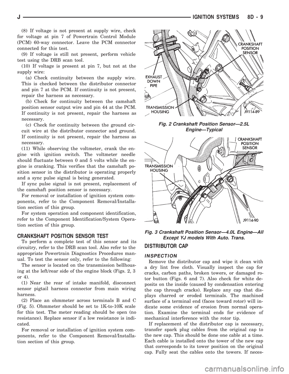
ing at the left/rear side of the engine block (Figs. 2, 3
or 4).
(1) Near the rear of intake manifold, disconnect
sensor pigtail harness connector from main wiring
harness.
(2) Place an ohmmeter across terminals B and C
(Fig. 5). Ohmmeter should be set to 1K-to-10K scale
for this test. The meter reading should be open (no
resistance). Replace sensor if a low resistance is indi-
cated.
For removal or installation of ignition system com-
ponents, refer to the Component Removal/Installa-
tion section of this group.
DISTRIBUTOR CAP
INSPECTION
Remove the distributor cap and wipe it clean with
a dry lint free cloth. Visually inspect the cap for
cracks, carbon paths, broken towers, or damaged ro-
tor button (Figs. 6 and 7). Also check for white de-
posits on the inside (caused by condensation entering
the cap through cracks). Replace any cap that dis-
plays charred or eroded terminals. The machined
surface of a terminal end (faces toward rotor) will in-
dicate some evidence of erosion from normal opera-
tion. Examine the terminal ends for evidence of
mechanical interference with the rotor tip.
If replacement of the distributor cap is necessary,
transfer spark plug cables from the original cap to
the new cap. This should be done one cable at a time.
Each cable is installed onto the tower of the new cap
that corresponds to its tower position on the original
cap. Fully seat the cables onto the towers. If neces-
Fig. 2 Crankshaft Position SensorÐ2.5L
EngineÐTypical
Fig. 3 Crankshaft Position SensorÐ4.0L EngineÐAll
Except YJ models With Auto. Trans.
JIGNITION SYSTEMS 8D - 9
Page 324 of 1784
IGNITION COIL
To perform a complete test of the ignition coil and
its circuitry, refer to the DRB scan tool. Also refer to
the appropriate Powertrain Diagnostics Procedures
manual. To test the coil only, refer to the following:
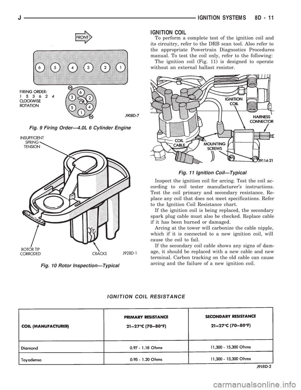
The ignition coil (Fig. 11) is designed to operate
without an external ballast resistor.
Inspect the ignition coil for arcing. Test the coil ac-
cording to coil tester manufacturer's instructions.
Test the coil primary and secondary resistance. Re-
place any coil that does not meet specifications. Refer
to the Ignition Coil Resistance chart.
If the ignition coil is being replaced, the secondary
spark plug cable must also be checked. Replace cable
if it has been burned or damaged.
Arcing at the tower will carbonize the cable nipple,
which if it is connected to a new ignition coil, will
cause the coil to fail.
If the secondary coil cable shows any signs of dam-
age, it should be replaced with a new cable and new
terminal. Carbon tracking on the old cable can cause
arcing and the failure of a new ignition coil.
IGNITION COIL RESISTANCE
Fig. 9 Firing OrderÐ4.0L 6 Cylinder Engine
Fig. 10 Rotor InspectionÐTypical
Fig. 11 Ignition CoilÐTypical
JIGNITION SYSTEMS 8D - 11
Page 325 of 1784
ENGINE COOLANT TEMPERATURE SENSOR TEST
To perform a complete test of this sensor and its
circuitry, refer to the DRB scan tool. Also refer to the
appropriate Powertrain Diagnostics Procedures man-
ual. To test the sensor only, refer to the following:
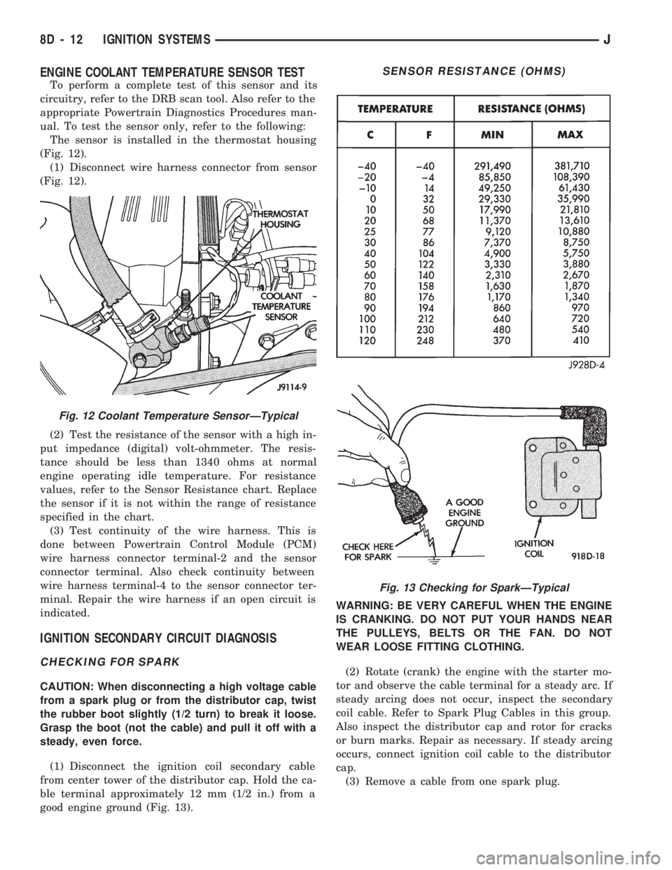
The sensor is installed in the thermostat housing
(Fig. 12).
(1) Disconnect wire harness connector from sensor
(Fig. 12).
(2) Test the resistance of the sensor with a high in-
put impedance (digital) volt-ohmmeter. The resis-
tance should be less than 1340 ohms at normal
engine operating idle temperature. For resistance
values, refer to the Sensor Resistance chart. Replace
the sensor if it is not within the range of resistance
specified in the chart.
(3) Test continuity of the wire harness. This is
done between Powertrain Control Module (PCM)
wire harness connector terminal-2 and the sensor
connector terminal. Also check continuity between
wire harness terminal-4 to the sensor connector ter-
minal. Repair the wire harness if an open circuit is
indicated.
IGNITION SECONDARY CIRCUIT DIAGNOSIS
CHECKING FOR SPARK
CAUTION: When disconnecting a high voltage cable
from a spark plug or from the distributor cap, twist
the rubber boot slightly (1/2 turn) to break it loose.
Grasp the boot (not the cable) and pull it off with a
steady, even force.
(1) Disconnect the ignition coil secondary cable
from center tower of the distributor cap. Hold the ca-
ble terminal approximately 12 mm (1/2 in.) from a
good engine ground (Fig. 13).WARNING: BE VERY CAREFUL WHEN THE ENGINE
IS CRANKING. DO NOT PUT YOUR HANDS NEAR
THE PULLEYS, BELTS OR THE FAN. DO NOT
WEAR LOOSE FITTING CLOTHING.
(2) Rotate (crank) the engine with the starter mo-
tor and observe the cable terminal for a steady arc. If
steady arcing does not occur, inspect the secondary
coil cable. Refer to Spark Plug Cables in this group.
Also inspect the distributor cap and rotor for cracks
or burn marks. Repair as necessary. If steady arcing
occurs, connect ignition coil cable to the distributor
cap.
(3) Remove a cable from one spark plug.
Fig. 12 Coolant Temperature SensorÐTypical
SENSOR RESISTANCE (OHMS)
Fig. 13 Checking for SparkÐTypical
8D - 12 IGNITION SYSTEMSJ