1994 JEEP CHEROKEE tow
[x] Cancel search: towPage 16 of 1784
ENGINE OIL CHANGE AND FILTER REPLACEMENT
WARNING: CARE SHOULD BE TAKEN WHEN
CHANGING OIL. PROTECTIVE CLOTHING AND
GLOVES SHOULD BE WORN. EXPOSED SKIN
SHOULD BE WASHED WITH SOAP AND WATER TO
REMOVE ANY ENGINE OIL. DO NOT USE GASO-
LINE, THINNER, OR SOLVENTS TO REMOVE EN-
GINE OIL FROM SKIN.
REQUIRED MAINTENANCE
With normal driving conditions, engine oil and fil-
ter must be changed after each 12 000-km (7,500-
miles)/12-month interval. If the vehicle is involved
with a severe driving condition, after each 4 800-km
(3,000-miles)/3-month interval. A severe driving con-
dition includes:
²frequent short trip driving less than 24 km (15
miles);
²frequent driving in a dusty environment;
²trailer towing;
²extensive engine idling;
²sustained high-speed operation;
²desert operation;
²frequent starting and stopping;
²cold-climate operation;
²off-road driving; or
²commercial service.
OIL CHANGE AND FILTER REPLACEMENT
(1) Drain the engine oil from the crankcase. Wait
until after the engine has attained the normal oper-
ating temperature to ensure complete drainage of oil.
(2) Install the drain-hole plug with a replacement
gasket.
The oil filter should be replaced during every
engine oil change.
(3)
Rotate the oil filter counterclockwise to remove
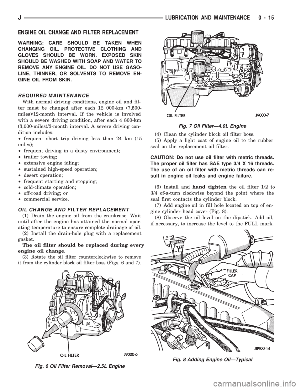
it from the cylinder block oil filter boss (Figs. 6 and 7).
(4) Clean the cylinder block oil filter boss.
(5) Apply a light coat of engine oil to the rubber
seal on the replacement oil filter.
CAUTION: Do not use oil filter with metric threads.
The proper oil filter has SAE type 3/4 X 16 threads.
The use of an oil filter with metric threads can re-
sult in engine oil leaks and engine failure.
(6) Install andhand tightenthe oil filter 1/2 to
3/4 of-a-turn clockwise beyond the point where the
seal first contacts the cylinder block.
(7) Add engine oil in fill hole located on top of en-
gine cylinder head cover (Fig. 8).
(8) Observe the oil level on the dipstick. Add oil,
if necessary, to increase the level to the FULL mark.
Fig. 6 Oil Filter RemovalÐ2.5L Engine
Fig. 7 Oil FilterÐ4.0L Engine
Fig. 8 Adding Engine OilÐTypical
JLUBRICATION AND MAINTENANCE 0 - 15
Page 19 of 1784

In areas of the country where carbon monoxide lev-
els are high, gasolines are being treated with oxy-
genated materials such as MTBE, ETBE and
ethanol.
Chrysler Corporation supports these efforts toward
cleaner air and recommends the use of these gaso-
lines as they become available.
IGNITION CABLES, DISTRIBUTOR CAP AND
ROTOR
REQUIRED IGNITION SYSTEM MAINTENANCE
The ignition cables, distributor cap and rotor must
be replaced after each 96 000-km (60,000-miles). Re-
fer to Group 8DÐIgnition Systems for additional in-
formation.
IGNITION TIMING
The ignition timing for 2.5L and 4.0L engines is
not adjustable. Refer to the specifications listed on
the engine Emission Control Information Label. Re-
fer to Group 25ÐEmission Control Systems for addi-
tional information.
SPARK PLUGS
REQUIRED MAINTENANCE
The spark plugs must be replaced after each 48
000-km (30,000-miles). Refer to the Spark Plugs
chart below and to Group 8DÐIgnition Systems for
additional information.
BATTERY
RECOMMENDED MAINTENANCE
The battery electrolyte level should be checked and
the cable clamps should be inspected for corrosion.
This should be done when the oil is changed and the
oil filter is replaced.
The battery cables should be inspected for abnor-
mal clamp and battery terminal post corrosion. Ser-
vice the terminals and cable clamps as necessary.In addition, the general condition of the battery
should be determined before the start of cold and hot
weather seasons. If the battery condition is marginal
or worse, it should be replaced.
Care should be taken when disposing a bat-
tery after removal from a vehicle. Lead-acid bat-
teries are highly poisonous and, when
indiscriminately disposed, could create a prob-
lem for the environment. Contact the applicable
local city or county government agency to deter-
mine where automobile (lead-acid) batteries can
be properly disposed in the local area.
INSPECTION/SERVICE
WARNING: WEAR SAFETY GLASSES, RUBBER
GLOVES AND PROTECTIVE CLOTHING WHEN HAN-
DLING/SERVICING A BATTERY. THE BATTERY
ELECTROLYTE CONTAINS SULFURIC ACID AND
WILL CAUSE HARM IF IT CONTACTS SKIN, EYES
OR CLOTHING. IT WILL ALSO DAMAGE PAINTED
(AS WELL AS UN-PAINTED) SURFACES OF A VEHI-
CLE. IF SULFURIC ACID CONTACTS ANY OF
THESE, FLUSH IMMEDIATELY WITH LARGE
AMOUNTS OF WATER. IF SULFURIC ACID CON-
TACTS SKIN OR EYES, GET IMMEDIATE MEDICAL
ATTENTION. DO NOT SMOKE IN THE VICINITY OF
A BATTERY. KEEP OPEN FLAMES AND SPARKS
AWAY FROM BATTERY FILLER CAPS BECAUSE
EXPLOSIVE GAS IS ALWAYS PRESENT.
(1) Disconnect the battery negative cable and then
the positive cable.
(2) Clean the battery cable clamps and terminal
posts with a wire brush and a battery terminal
cleaner.
(3) Pry the battery cell filler caps upward to re-
move them and inspect each filler well (low-mainte-
nance batteries only, not applicable to maintenance-
free batteries). It could possibly be necessary to
loosen the battery holddown clamp to remove the
caps. Maintain the electrolyte level above the battery
plates and at the bottom of the filler well ring. Add
distilled water or low-mineral content drinking wa-
ter, if necessary. In freezing weather (below 0ÉC/
32ÉF), add the water just before driving to ensure
that it mixes thoroughly with the electrolyte. This
will prevent it from freezing.
(4) Remove the battery holddown strap and clean
the battery case/battery tray.Clean with bicarbonate
of soda (baking soda) and water. Rinse and dry the
battery case/tray thoroughly after cleaning.
(5) Position the battery in the tray and install the
holddown strap.Do not over-tighten the nuts.
(6) Connect the battery positive cable and then the
negative cable to the battery.
SPARK PLUGS
0 - 18 LUBRICATION AND MAINTENANCEJ
Page 27 of 1784
If the transfer case ATF is warm, it is accept-
able for the fluid to drip out of the fill hole. If
the fluid gushes out of the fill hole, the level is
too high.
(3) If the level is low, raise it to the bottom edge of
the fill hole with MOPAR ATF PLUS type 7176 or
an equivalent MerconŸ/Dexron IIŸ ATF.
(4) Install the fill-hole plug. Tighten the plug with
47 NIm (35 ft. lbs.) torque.
(5) Remove the support and lower the vehicle.
FLUID CHANGE
When it becomes necessary to change the ATF in a
Jeepttransfer case, use the following procedure.
(1) Raise and support the vehicle.
(2) Remove the fill-hole plug from the transfer
case.
(3) Place an appropriate container under the trans-
fer case drain-hole plug.
(4) Remove the drain-hole plug and drain the ATF
from the transfer case into the container.
Care should be exercised when disposing used
ATF after it has been drained from a transfer
case.
CAUTION: Do not over-tighten the drain and fill-hole
plugs. Over-tightening can strip the hole threads
and/or crack the aluminum housing.
(5) Install the drain-hole plug in the transfer case.
Tighten the plug with 47 NIm (35 ft. lbs.) torque.
(6) Fill the transfer case to the bottom edge of the
fill hole with MOPAR ATF PLUS type 7176 (or an
equivalent MerconŸ/Dexron IIŸ ATF).
(7) Install the fill-hole plug in the transfer case.
Tighten the plug with 47 NIm (35 ft. lbs.) torque.
(8) Remove the support and lower the vehicle.
FRONT AND REAR AXLES
RECOMMENDED MAINTENANCE
The lubricant level in axle differential housings
should be determined at the same time as the engine
oil is changed and the oil filter is replaced. Add lu-
bricant as necessary.
In addition, with normal driving conditions, the
axle lubricant should be changed after each 48
000-km (30,000-miles). With severe driving condi-
tions, after each 29 000-km (12,000-miles).
LUBRICANT SPECIFICATIONS
For normal vehicle operation, use SAE 75W-90,
API Quality Grade GL-5 gear lubricant in all Jeept
front (4WD only) and rear axles. Vehicles equipped
with a Trac-Loc rear axle also require a friction mod-
ifier additive with the gear lubricant.
When involved in trailer towing applications
use SAE 80W-140, API Quality Grade GL-5 gearlubricant in the rear axle. XJ Vehicles equipped
with a class III trailer hitch require SAE
75W-140 synthetic gear lubricant in the rear
axle.
LUBRICANT LEVEL
Determine the axle differential housing lubricant
level according to the following procedure.
(1) Raise and support the vehicle.
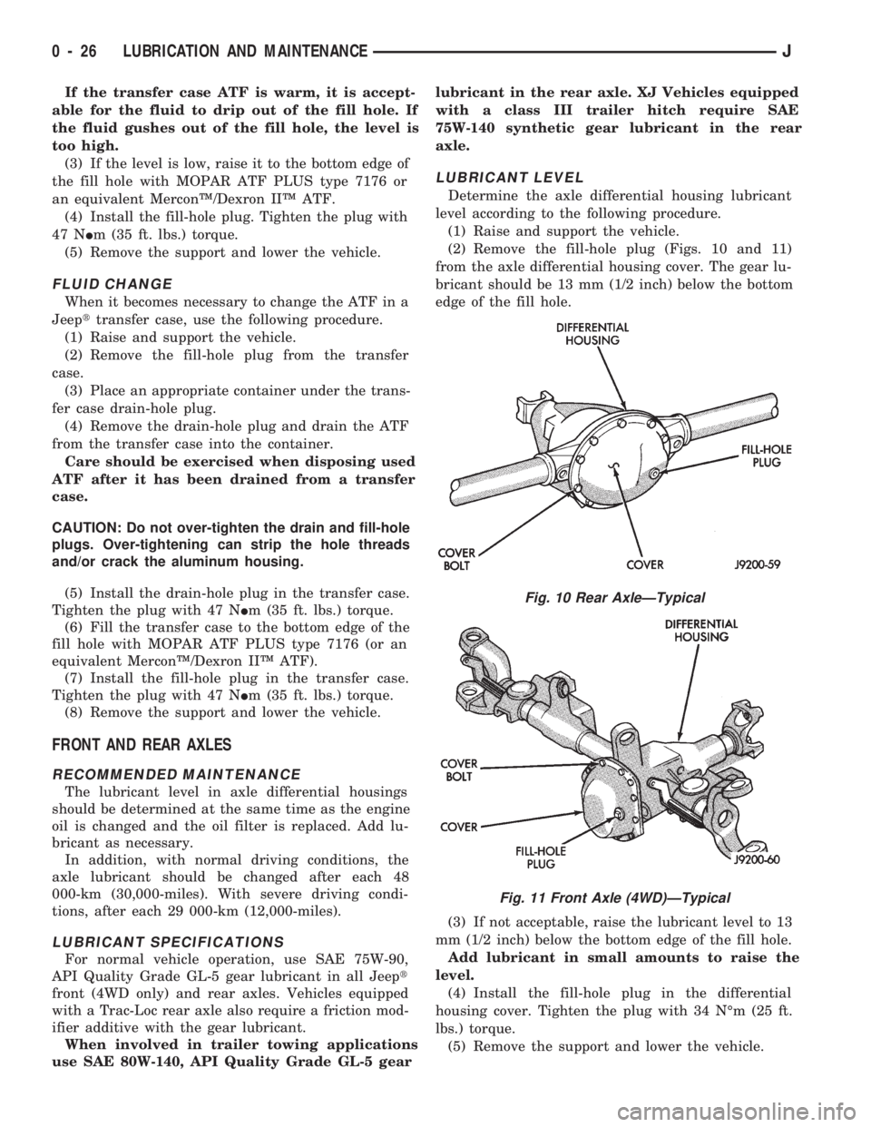
(2) Remove the fill-hole plug (Figs. 10 and 11)
from the axle differential housing cover. The gear lu-
bricant should be 13 mm (1/2 inch) below the bottom
edge of the fill hole.
(3) If not acceptable, raise the lubricant level to 13
mm (1/2 inch) below the bottom edge of the fill hole.
Add lubricant in small amounts to raise the
level.
(4) Install the fill-hole plug in the differential
housing cover. Tighten the plug with 34 NÉm (25 ft.
lbs.) torque.
(5) Remove the support and lower the vehicle.
Fig. 10 Rear AxleÐTypical
Fig. 11 Front Axle (4WD)ÐTypical
0 - 26 LUBRICATION AND MAINTENANCEJ
Page 43 of 1784
not change except when a spindle or ball stud is
damaged or bent. The angle is not adjustable and the
damaged component(s) must be replaced to correct
mis-alignment.
CAUTION:Do not attempt to modify any suspension
or steering component by heating and bending.
PRE-ALIGNMENT INSPECTION
Before starting a front wheel alignment, the follow-
ing inspection and necessary corrections must be
completed.
(1) Tires with the same recommended air pressure,
size, and thread wear. Refer to Group 22, Tires And
Wheels for diagnosis information.
(2) Front wheel bearings for wear.
(3) Ball studs, steering linkage pivot points and
steering gear for looseness, roughness, binding or
wear. Refer to Group 19, Steering for additional in-
formation.
(4) Front wheels for excessive radial or lateral
runout and unbalance. Refer to Group 22, Tires And
Wheels for diagnosis information.
(5) Suspension components for wear and noise.
Check components for correct torque. Refer to Groups
2 and 3, Suspension and Axle for additional informa-
tion.
ALIGNMENT MEASUREMENTS AND ADJUSTMENTS
Before each alignment reading, the vehicle should
be jounced (rear first, then front). Grasp each bumper
at the center and jounce the vehicle up and down
several times. Always release the bumper in the
down position.Set the front end alignment to
specifications with the vehicle at its NOR-
MALLY RIDE HEIGHT.
CAMBER
The wheel camber angle (Fig. 1) is preset at ZERO
DEGREES (0É). The angle is not adjustable and can-
not be altered.
CASTER
The caster angle (Fig. 1) is set at:
²XJ manual transmission, POSITIVE 6.5 DE-
GREES (+6.5É).
²XJ automatic transmission, POSITIVE 8.0 DE-
GREES (+8.0É).
²YJ all transmissions, POSITIVE 6.0 DEGREES
(+6.0É).
Before checking the caster of the front axle for cor-
rect angle. Be sure the axle is not bent or twisted.
Road test the vehicle, and make left and right
turns. If the steering wheel returns to the center po-
sition unassisted, the caster angle is correct. How-ever, if steering wheel does not return toward the
center position unassisted, an incorrect caster angle
is probable.
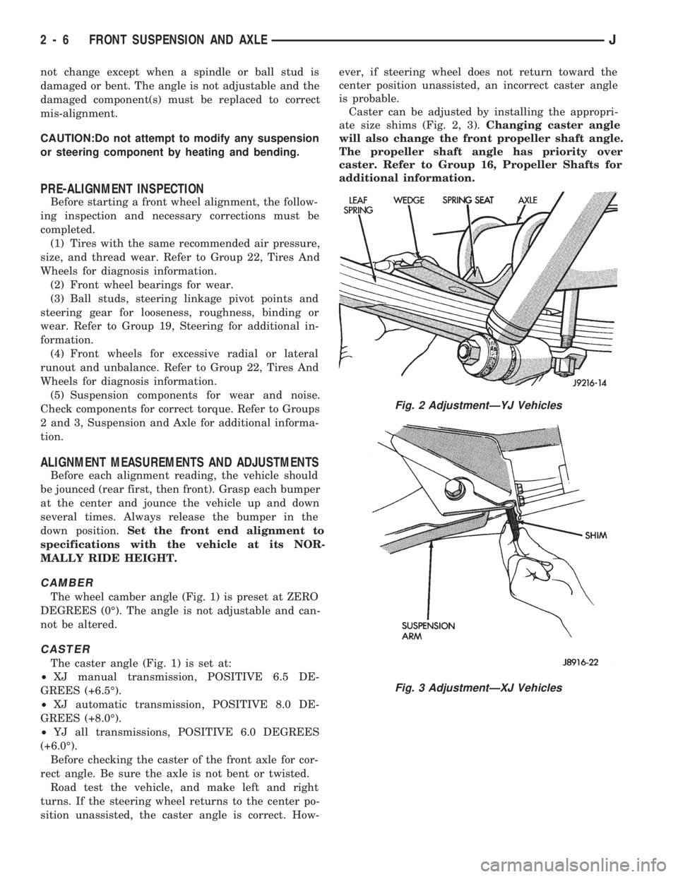
Caster can be adjusted by installing the appropri-
ate size shims (Fig. 2, 3).Changing caster angle
will also change the front propeller shaft angle.
The propeller shaft angle has priority over
caster. Refer to Group 16, Propeller Shafts for
additional information.
Fig. 2 AdjustmentÐYJ Vehicles
Fig. 3 AdjustmentÐXJ Vehicles
2 - 6 FRONT SUSPENSION AND AXLEJ
Page 49 of 1784
(2) Install the bolts and finger tighten the nuts
(Fig. 3).
(3) Remove support and lower the vehicle.
(4) Tighten the front and rear nuts to 115 Nzm (85
ft. lbs.) torque.
SPRING AND SHOCK DIAGNOSIS
A squeak noise from the shock absorber can be pro-
duced if movement between the rubber bushings and
the metal occurs. This noise can usually be stopped
by tightening the attaching nuts. If the squeak noisepersists, inspect for damaged and worn bushings, and
attaching components. Repair as necessary.
The shock absorber bushings do not require any
type of lubrication. Do not lubricate the bushings to
reduce bushing noise. Grease or mineral oil-base lu-
bricants will deteriorate the bushing rubber.
The shock absorbers are not refillable or adjust-
able. If a malfunction occurs, the shock absorber
must be replaced. To test a shock absorber, hold it in
an upright position and force the piston into and out
of the cylinder four or five times. The action through-
out each stroke should be smooth and even.
SHOCK ABSORBER
REMOVAL
(1) Remove the nut, retainer and grommet from
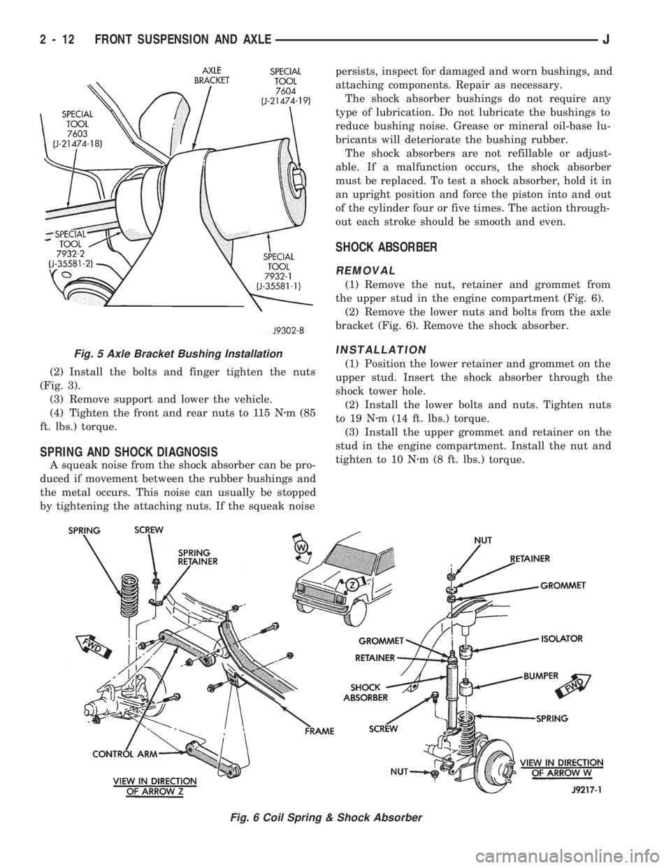
the upper stud in the engine compartment (Fig. 6).
(2) Remove the lower nuts and bolts from the axle
bracket (Fig. 6). Remove the shock absorber.
INSTALLATION
(1) Position the lower retainer and grommet on the
upper stud. Insert the shock absorber through the
shock tower hole.
(2) Install the lower bolts and nuts. Tighten nuts
to 19 Nzm (14 ft. lbs.) torque.
(3) Install the upper grommet and retainer on the
stud in the engine compartment. Install the nut and
tighten to 10 Nzm (8 ft. lbs.) torque.
Fig. 6 Coil Spring & Shock Absorber
Fig. 5 Axle Bracket Bushing Installation
2 - 12 FRONT SUSPENSION AND AXLEJ
Page 51 of 1784
STABILIZER BAR
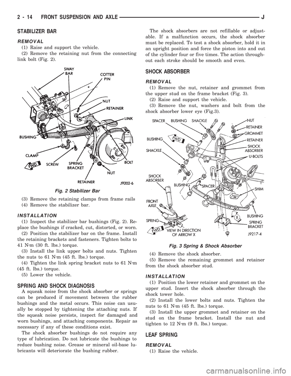
REMOVAL
(1) Raise and support the vehicle.
(2) Remove the retaining nut from the connecting
link bolt (Fig. 2).
(3) Remove the retaining clamps from frame rails
(4) Remove the stabilizer bar.
INSTALLATION
(1) Inspect the stabilizer bar bushings (Fig. 2). Re-
place the bushings if cracked, cut, distorted, or worn.
(2) Position the stabilizer bar on the frame. Install
the retaining brackets and fasteners. Tighten bolts to
41 Nzm (30 ft. lbs.) torque.
(3) Install the link upper bolts and nuts. Tighten
the nuts to 61 Nzm (45 ft. lbs.) torque.
(4) Tighten the link spring bracket nuts to 61 Nzm
(45 ft. lbs.) torque.
(5) Lower the vehicle.
SPRING AND SHOCK DIAGNOSIS
A squeak noise from the shock absorber or springs
can be produced if movement between the rubber
bushings and the metal occurs. This noise can usu-
ally be stopped by tightening the attaching nuts. If
the squeak noise persists, inspect for damaged and
worn bushings, and attaching components. Repair as
necessary if any of these conditions exist.
The shock absorber bushings do not require any
type of lubrication. Do not lubricate the bushings to
reduce bushing noise. Grease or mineral oil-base lu-
bricants will deteriorate the bushing rubber.The shock absorbers are not refillable or adjust-
able. If a malfunction occurs, the shock absorber
must be replaced. To test a shock absorber, hold it in
an upright position and force the piston into and out
of the cylinder four or five times. The action through-
out each stroke should be smooth and even.
SHOCK ABSORBER
REMOVAL
(1) Remove the nut, retainer and grommet from
the upper stud on the frame bracket (Fig. 3).
(2) Raise and support the vehicle.
(3) Remove the nut, washers and bolt from the
shock absorber lower eye (Fig.3).
(4) Remove the shock absorber.
(5) Remove the remaining grommet and retainer
from the shock absorber stud.
INSTALLATION
(1) Position the lower retainer and grommet on the
upper stud. Insert the shock absorber through the
shock tower hole.
(2) Install the lower bolts and nuts. Tighten the
nuts to 61 Nzm (45 ft. lbs.) torque.
(3) Install the upper grommet and retainer on the
stud on the frame bracket. Install the nut and
tighten to 12 Nzm (9 ft. lbs.) torque.
LEAF SPRING
REMOVAL
(1) Raise the vehicle.
Fig. 2 Stabilizer Bar
Fig. 3 Spring & Shock Absorber
2 - 14 FRONT SUSPENSION AND AXLEJ
Page 53 of 1784
AXLE NOISE/VIBRATION DIAGNOSIS
INDEX
page page
Driveline Snap........................... 17
Gear and Bearing Noise................... 16
General Information....................... 16Low Speed Knock........................ 17
Vibration............................... 17
GENERAL INFORMATION
Axle bearing problem conditions are usually caused
by:
²Insufficient or incorrect lubricant
²Foreign matter/water contamination
²Incorrect bearing preload torque adjustment
²Incorrect backlash (to tight)
When serviced, the bearings must be cleaned thor-
oughly. They should be dried with lint-free shop tow-
els.Never dry bearings with compressed air.
This will overheat them and brinell the bearing
surfaces. This will result in noisy operation after
repair.
Axle gear problem conditions are usually the result
of:
²Insufficient lubrication
²Incorrect or contaminated lubricant
²Overloading (excessive engine torque) or exceeding
vehicle weight capacity
²Incorrect clearance or backlash adjustment
Insufficient lubrication is usually the result of a
housing cover leak. It can also be from worn axle
shaft or pinion gear seals. Check for cracks or porous
areas in the housing or tubes.
Using the wrong lubricant will cause overheating
and gear failure. Gear tooth cracking and bearing
spalling are indicators of this.
Axle component breakage is most often the result
of:
²Severe overloading
²Insufficient lubricant
²Incorrect lubricant
²Improperly tightened components
Overloading occurs when towing heavier than rec-
ommended loads. Component breakage can occur
when the wheels are spun excessively. Incorrect lu-
bricant quantity contributes to breakage. Loose dif-
ferential components can also cause breakage.
Incorrect bearing preload or gear backlash will not
result in component breakage. Mis-adjustment will
produce enough noise to cause service repair before a
failure occurs. If a mis-adjustment condition is not
corrected, component failure can result.
Excessive bearing preload may not be noisy. This
condition will cause high temperature which can re-
sult in bearing failure.
GEAR AND BEARING NOISE
GEAR NOISE
Axle gear noise can be caused by insufficient lubri-
cant. Incorrect backlash, tooth contact, or worn/dam-
aged gears can cause noise.
Gear noise usually happens at a specific speed
range. The range is 30 to 40 mph, or above 50 mph.
The noise can also occur during a specific type of
driving condition. These conditions are acceleration,
deceleration, coast, or constant load.
When road testing, accelerate the vehicle to the
speed range where the noise is the greatest. Shift
out-of-gear and coast through the peak-noise range.
If the noise stops or changes greatly, check for insuf-
ficient lubricant. Incorrect ring gear backlash, or
gear damage can cause noise changes.
Differential side and pinion gears can be checked
by turning the vehicle. They usually do not cause
noise in straight-ahead driving. These gears are
loaded during vehicle turns. If noise does occur dur-
ing vehicle turns, the side or pinion gears could be
worn or damaged. A worn pinion gear mate shaft can
also cause a snapping or a knocking noise.
BEARING NOISE
The axle shaft, differential and pinion gear bear-
ings can all produce noise when worn or damaged.
Bearing noise can be either a whining, or a growling
sound.
Pinion gear bearings have a constant-pitch noise.
This noise changes only with vehicle speed. Pinion
bearing noise will be higher because it rotates at a
faster rate. Drive the vehicle and load the differen-
tial. If bearing noise occurs the pinion rear bearing is
the source of the noise. If the bearing noise is heard
during a coast, front bearing is the source.
Worn, damaged differential bearings usually pro-
duce a low pitch noise. Differential bearing noise is
similar to pinion bearing. The pitch of differential
bearing noise is also constant and varies only with
vehicle speed.
Axle shaft bearings produce noise and vibration
when worn or damaged. The noise generally changes
when the bearings are loaded. Road test the vehicle.
Turn the vehicle sharply to the left and to the right.
This will load the bearings and change the noise
2 - 16 FRONT SUSPENSION AND AXLEJ
Page 66 of 1784
SHIFT MOTOR Ð REMOVAL/DISASSEMBLY
(1) Disconnect the vacuum and wiring connector
from the shift housing.
(2) Remove indicator switch.
(3) Remove the shift motor housing cover, gasket
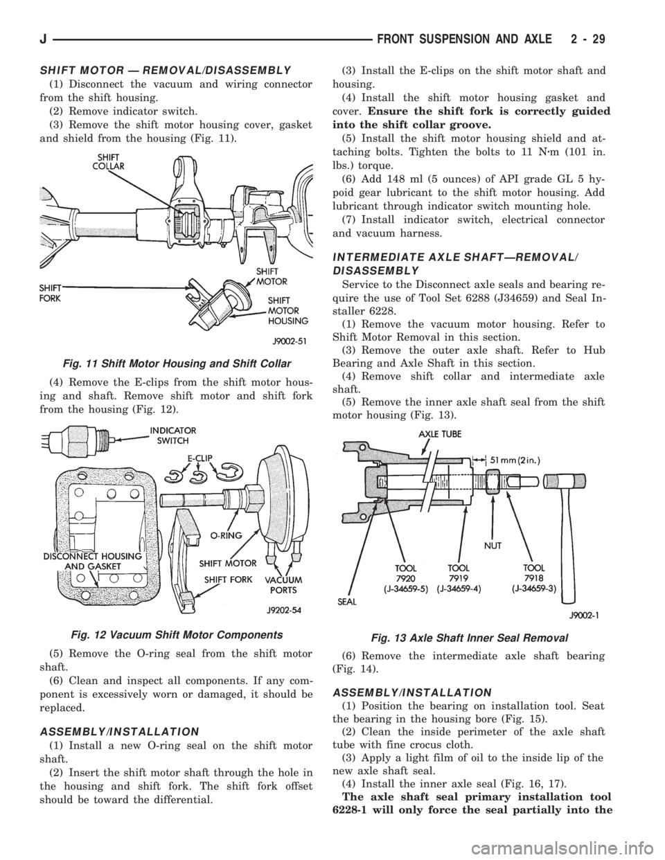
and shield from the housing (Fig. 11).
(4) Remove the E-clips from the shift motor hous-
ing and shaft. Remove shift motor and shift fork
from the housing (Fig. 12).
(5) Remove the O-ring seal from the shift motor
shaft.
(6) Clean and inspect all components. If any com-
ponent is excessively worn or damaged, it should be
replaced.
ASSEMBLY/INSTALLATION
(1) Install a new O-ring seal on the shift motor
shaft.
(2) Insert the shift motor shaft through the hole in
the housing and shift fork. The shift fork offset
should be toward the differential.(3) Install the E-clips on the shift motor shaft and
housing.
(4) Install the shift motor housing gasket and
cover.Ensure the shift fork is correctly guided
into the shift collar groove.
(5) Install the shift motor housing shield and at-
taching bolts. Tighten the bolts to 11 Nzm (101 in.
lbs.) torque.
(6) Add 148 ml (5 ounces) of API grade GL 5 hy-
poid gear lubricant to the shift motor housing. Add
lubricant through indicator switch mounting hole.
(7) Install indicator switch, electrical connector
and vacuum harness.
INTERMEDIATE AXLE SHAFTÐREMOVAL/
DISASSEMBLY
Service to the Disconnect axle seals and bearing re-
quire the use of Tool Set 6288 (J34659) and Seal In-
staller 6228.
(1) Remove the vacuum motor housing. Refer to
Shift Motor Removal in this section.
(3) Remove the outer axle shaft. Refer to Hub
Bearing and Axle Shaft in this section.
(4) Remove shift collar and intermediate axle
shaft.
(5) Remove the inner axle shaft seal from the shift
motor housing (Fig. 13).
(6) Remove the intermediate axle shaft bearing
(Fig. 14).
ASSEMBLY/INSTALLATION
(1) Position the bearing on installation tool. Seat
the bearing in the housing bore (Fig. 15).
(2) Clean the inside perimeter of the axle shaft
tube with fine crocus cloth.
(3) Apply a light film of oil to the inside lip of the
new axle shaft seal.
(4) Install the inner axle seal (Fig. 16, 17).
The axle shaft seal primary installation tool
6228-1 will only force the seal partially into the
Fig. 11 Shift Motor Housing and Shift Collar
Fig. 12 Vacuum Shift Motor ComponentsFig. 13 Axle Shaft Inner Seal Removal
JFRONT SUSPENSION AND AXLE 2 - 29