1994 JEEP CHEROKEE tow
[x] Cancel search: towPage 143 of 1784
(3) Lower the vehicle.
PARK NEUTRAL SWITCH
Refer to Group 21, Transmissions for park neutral
switch service.
POWER STEERING PRESSURE SWITCHÐ2.5L
ENGINE ONLY
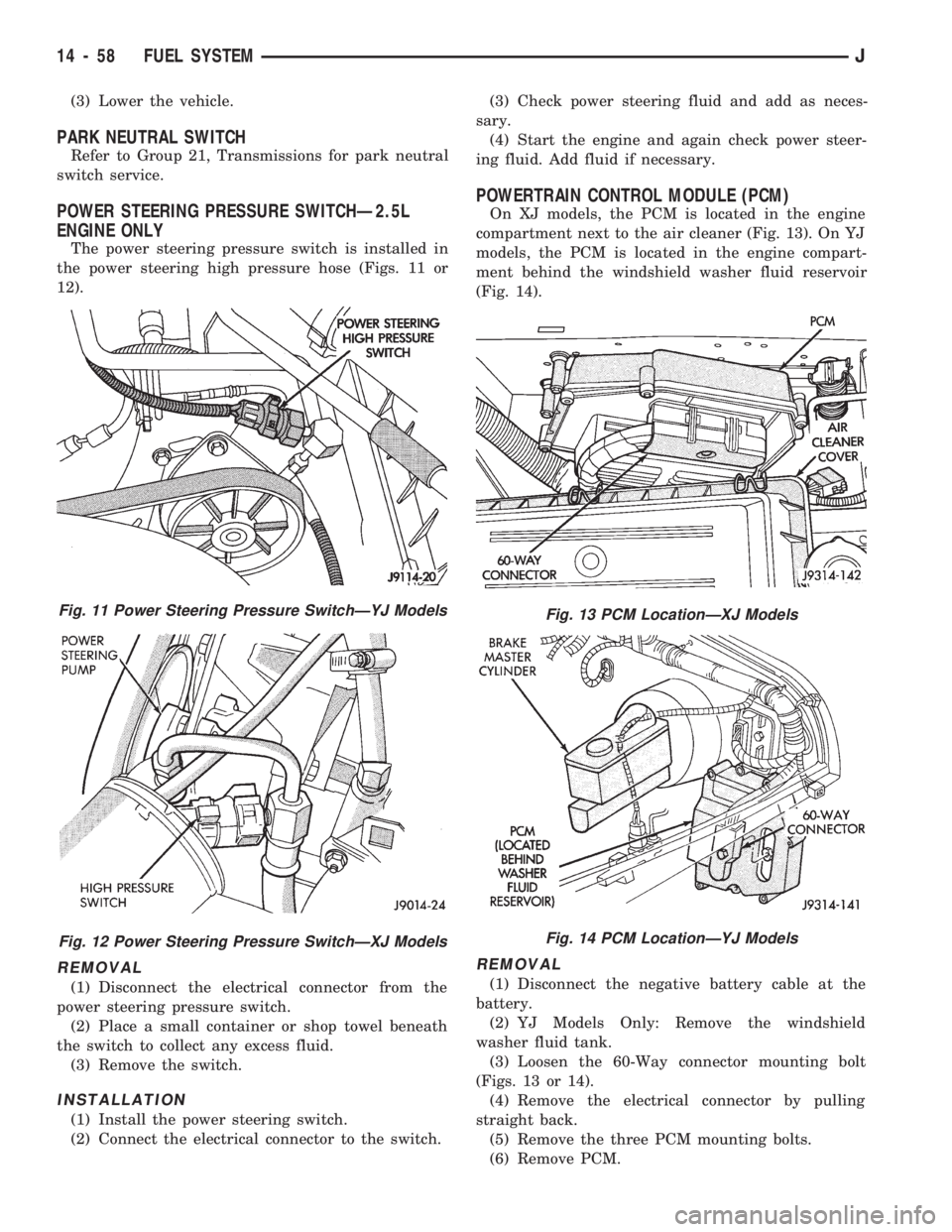
The power steering pressure switch is installed in
the power steering high pressure hose (Figs. 11 or
12).
REMOVAL
(1) Disconnect the electrical connector from the
power steering pressure switch.
(2) Place a small container or shop towel beneath
the switch to collect any excess fluid.
(3) Remove the switch.
INSTALLATION
(1) Install the power steering switch.
(2) Connect the electrical connector to the switch.(3) Check power steering fluid and add as neces-
sary.
(4) Start the engine and again check power steer-
ing fluid. Add fluid if necessary.
POWERTRAIN CONTROL MODULE (PCM)
On XJ models, the PCM is located in the engine
compartment next to the air cleaner (Fig. 13). On YJ
models, the PCM is located in the engine compart-
ment behind the windshield washer fluid reservoir
(Fig. 14).
REMOVAL
(1) Disconnect the negative battery cable at the
battery.
(2) YJ Models Only: Remove the windshield
washer fluid tank.
(3) Loosen the 60-Way connector mounting bolt
(Figs. 13 or 14).
(4) Remove the electrical connector by pulling
straight back.
(5) Remove the three PCM mounting bolts.
(6) Remove PCM.
Fig. 11 Power Steering Pressure SwitchÐYJ Models
Fig. 12 Power Steering Pressure SwitchÐXJ Models
Fig. 13 PCM LocationÐXJ Models
Fig. 14 PCM LocationÐYJ Models
14 - 58 FUEL SYSTEMJ
Page 160 of 1784
BRAKE BLEEDINGÐBRAKE FLUID AND LEVELÐBRAKELINES AND HOSES
INDEX
page page
Brake BleedingÐXJ/YJ with ABS Brakes....... 14
Brake BleedingÐXJ/YJ with Standard Brakes . . . 13
Brake Fluid Contamination.................. 13
Brake Fluid Level........................ 13Brakeline Charts......................... 15
Brakelines and Hoses..................... 15
Combination Valve....................... 15
Recommended Brake Fluid................. 13
RECOMMENDED BRAKE FLUID
The only brake fluid recommended for Jeep vehi-
cles with standard or antilock brakes, is Mopar brake
fluid, or an equivalent fluid meeting SAE J1703 and
DOT 3 standards.
Use new brake fluid only to top off the master
cylinder or refill the system. Never use re-
claimed fluid, fluid not meeting the SAE/DOT
standards or fluid from an unsealed container.
Do not use fluid from any container that has
been left open for any length of time. Fluid in
open containers can absorb moisture.
BRAKE FLUID LEVEL
Always clean the master cylinder and cover before
checking fluid level. If not cleaned, dirt from the
cover could enter the fluid. Also check the cover seal
and replace it if torn or distorted.
Correct fluid level is to within 6 mm (1/4 in.) of the
reservoir rim, or to the fill mark on models with a
plastic reservoir. Refer to the Antilock Brake section
for fluid levels on models equipped with ABS brakes.
BRAKE FLUID CONTAMINATION
Oil in the fluid will cause brake system rubber
seals to soften and swell. The seals may also become
porous and begin to deteriorate.
If fluid contamination is suspected, drain off a sam-
ple from the master cylinder. A suction gun or simi-
lar device can be used for this purpose.
Empty the drained fluid into a glass container.
Contaminants in the fluid will cause the fluid to sep-
arate into distinct layers. If contamination has oc-
curred, the system rubber seals, hoses and cups must
be replaced and the system thoroughly flushed with
clean brake fluid.
BRAKE BLEEDINGÐXJ/YJ WITH STANDARD
BRAKES
Use Mopar DOT 3 brake fluid, or an equivalent
meeting SAE/DOT standards J1703-F and DOT 3, to
fill and bleed the system.
On standard brake models, bleeding can be per-
formed either manually or with pressure equipment.
However, if pressure equipment is used, it will be
necessary to hold the front brake metering valveopen in order to bleed the front brakes. The valve
can be held open with a tension clip tool or by hand.
It will also be necessary that a suitable size pressure
tank hose adapter be available for use on the master
cylinder.
MANUAL BLEEDING PROCEDURE
(1) If master cylinder has been overhauled or a
new cylinder will be installed, bleed cylinder on
bench before installation. This shortens time needed
to bleed system and ensures proper cylinder opera-
tion.
(2) Wipe master cylinder reservoir and cap clean
with shop towels.
(3) Remove cover and fill master cylinder reservoir
with Mopar, or equivalent DOT 3 brake fluid.
(4) Open all caliper and wheel cylinder bleed
screws.
(5) Close bleed screws after fluid begins flowing
from each bleed screw.
(6) Top off master cylinder reservoir again.
(7) Use following bleed sequence:
²master cylinder
²right rear
²left rear
²right front
²left front
(8) Observe following brake bleeding precautions:
²Do not pump brake pedal at any time while bleed-
ing. Air in system will be compressed into small bub-
bles that are distributed throughout hydraulic
system. This will make a second and third bleeding
operation necessary.
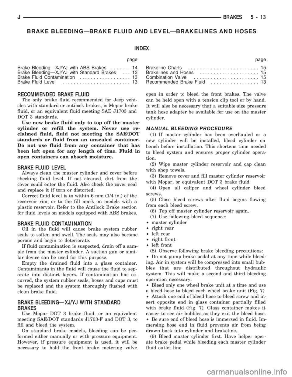
²Bleed only one wheel brake unit at a time and use
a bleed hose to bleed each wheel brake unit (Fig. 7).
²Attach one end of bleed hose to bleed screw and in-
sert opposite end in glass container partially filled
with brake fluid (Fig. 7). Glass container makes it
easier to see air bubbles as they exit the bleed hose.
²Be sure end of bleed hose is immersed in fluid. Im-
mersing hose end in fluid prevents air from being
drawn back into cylinder and brakeline.
(9) Bleed master cylinder first. Have helper oper-
ate brake pedal while bleeding each master cylinder
fluid outlet line.
JBRAKES 5 - 13
Page 167 of 1784
STANDARD MASTER CYLINDER
INDEX
page page
General Service Information................ 20
Master Cylinder Installation................. 20Master Cylinder Overhaul.................. 20
Master Cylinder Removal.................. 20
GENERAL SERVICE INFORMATION
The service information in this section covers the
standard (non-ABS) master cylinder only. The center
feed master cylinder used with the ABS system is
covered in the antilock brake component service sec-
tion.
MASTER CYLINDER REMOVAL
(1) Disconnect brake lines at master cylinder.
(2) Remove cylinder mounting nuts and remove
master cylinder.
(3) Remove cylinder cover and drain fluid.
MASTER CYLINDER INSTALLATION
(1) Bleed master cylinder on bench before installa-
tion. Refer to overhaul assembly procedure in this
section for bleeding method.
(2) Install cylinder on brake booster studs and in-
stall cylinder attaching nuts. Tighten nuts to 21 NIm
(15 ft. lbs.).
(3) Connect brakelines to cylinder.
(4) Fill and bleed brake system.
MASTER CYLINDER OVERHAUL
CYLINDER DISASSEMBLY
(1) Remove cylinder cover and drain fluid.
(2) Examine cylinder cover seal. Discard seal if
torn or distorted.
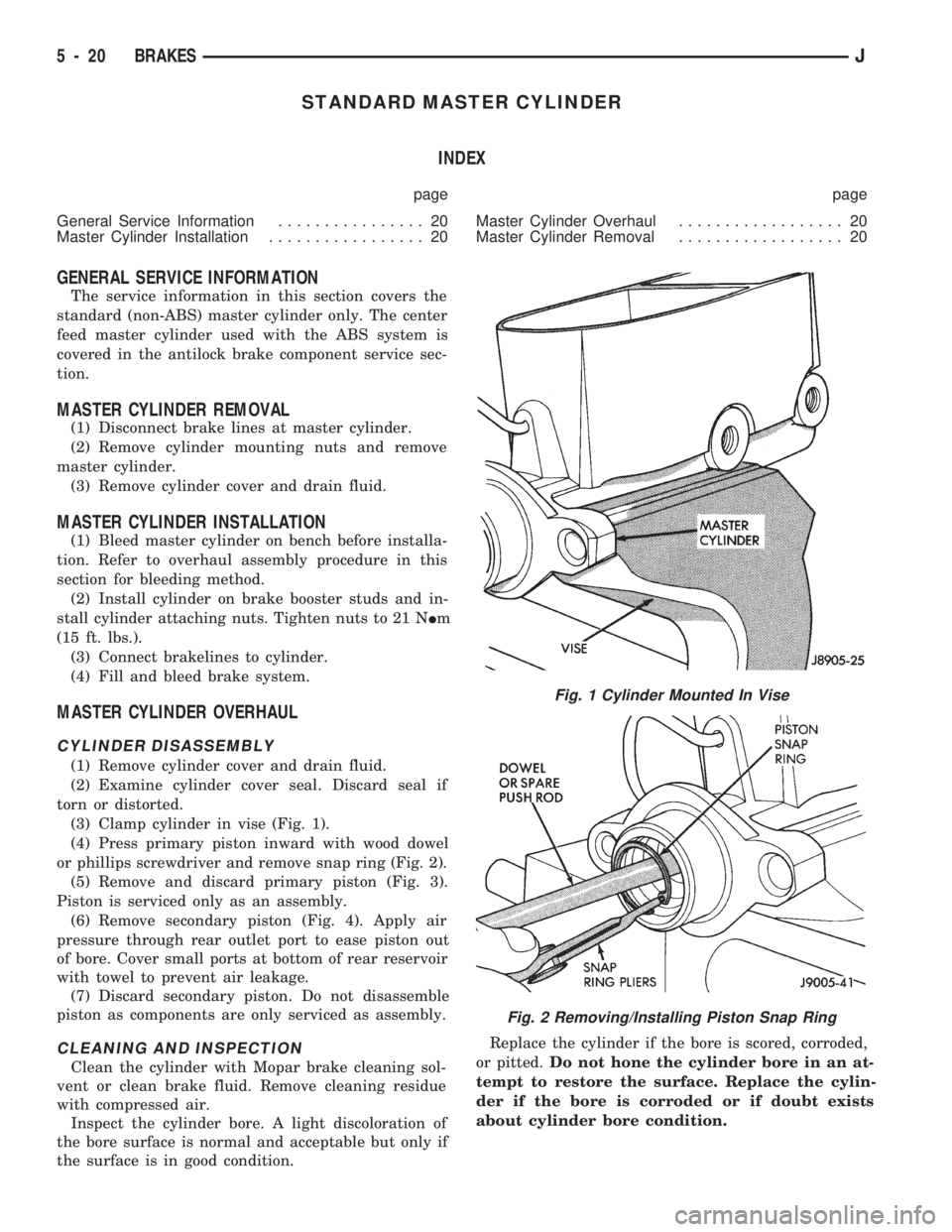
(3) Clamp cylinder in vise (Fig. 1).
(4) Press primary piston inward with wood dowel
or phillips screwdriver and remove snap ring (Fig. 2).
(5) Remove and discard primary piston (Fig. 3).
Piston is serviced only as an assembly.
(6) Remove secondary piston (Fig. 4). Apply air
pressure through rear outlet port to ease piston out
of bore. Cover small ports at bottom of rear reservoir
with towel to prevent air leakage.
(7) Discard secondary piston. Do not disassemble
piston as components are only serviced as assembly.
CLEANING AND INSPECTION
Clean the cylinder with Mopar brake cleaning sol-
vent or clean brake fluid. Remove cleaning residue
with compressed air.
Inspect the cylinder bore. A light discoloration of
the bore surface is normal and acceptable but only if
the surface is in good condition.Replace the cylinder if the bore is scored, corroded,
or pitted.Do not hone the cylinder bore in an at-
tempt to restore the surface. Replace the cylin-
der if the bore is corroded or if doubt exists
about cylinder bore condition.
Fig. 1 Cylinder Mounted In Vise
Fig. 2 Removing/Installing Piston Snap Ring
5 - 20 BRAKESJ
Page 173 of 1784
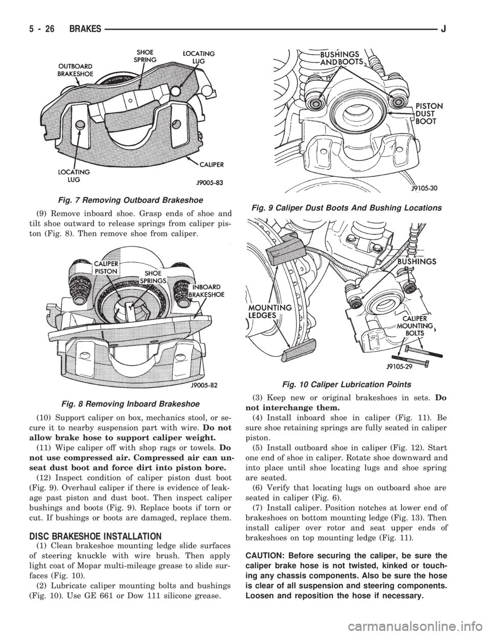
(9) Remove inboard shoe. Grasp ends of shoe and
tilt shoe outward to release springs from caliper pis-
ton (Fig. 8). Then remove shoe from caliper.
(10) Support caliper on box, mechanics stool, or se-
cure it to nearby suspension part with wire.Do not
allow brake hose to support caliper weight.
(11) Wipe caliper off with shop rags or towels.Do
not use compressed air. Compressed air can un-
seat dust boot and force dirt into piston bore.
(12) Inspect condition of caliper piston dust boot
(Fig. 9). Overhaul caliper if there is evidence of leak-
age past piston and dust boot. Then inspect caliper
bushings and boots (Fig. 9). Replace boots if torn or
cut. If bushings or boots are damaged, replace them.
DISC BRAKESHOE INSTALLATION
(1) Clean brakeshoe mounting ledge slide surfaces
of steering knuckle with wire brush. Then apply
light coat of Mopar multi-mileage grease to slide sur-
faces (Fig. 10).
(2) Lubricate caliper mounting bolts and bushings
(Fig. 10). Use GE 661 or Dow 111 silicone grease.(3) Keep new or original brakeshoes in sets.Do
not interchange them.
(4) Install inboard shoe in caliper (Fig. 11). Be
sure shoe retaining springs are fully seated in caliper
piston.
(5) Install outboard shoe in caliper (Fig. 12). Start
one end of shoe in caliper. Rotate shoe downward and
into place until shoe locating lugs and shoe spring
are seated.
(6) Verify that locating lugs on outboard shoe are
seated in caliper (Fig. 6).
(7) Install caliper. Position notches at lower end of
brakeshoes on bottom mounting ledge (Fig. 13). Then
install caliper over rotor and seat upper ends of
brakeshoes on top mounting ledge (Fig. 11).
CAUTION: Before securing the caliper, be sure the
caliper brake hose is not twisted, kinked or touch-
ing any chassis components. Also be sure the hose
is clear of all suspension and steering components.
Loosen and reposition the hose if necessary.
Fig. 7 Removing Outboard Brakeshoe
Fig. 8 Removing Inboard Brakeshoe
Fig. 9 Caliper Dust Boots And Bushing Locations
Fig. 10 Caliper Lubrication Points
5 - 26 BRAKESJ
Page 174 of 1784

(8) Install and tighten caliper mounting bolts to
10-20 Nzm (7-15 ft. lbs.) torque.
CAUTION: If new caliper bolts are being installed,
or if the original reason for repair was a drag/pull
condition, check caliper bolt length before proceed-
ing. If the bolts have a shank length greater than
67.6 mm (2.66 in.), they will contact the inboard
brakeshoe causing a partial apply condition. Refer
to Figure 14 for required caliper bolt length.
(9) Install wheels. Tighten lug nuts to 102 Nzm (75
ft. lbs.) torque.
(10) Pump brake pedal until caliper pistons and
brakeshoes are seated.
(11) Top off brake fluid level if necessary. Use Mo-
par brake fluid or equivalent meeting SAE J1703
and DOT 3 standards only.
CALIPER REMOVAL
(1) Raise vehicle and remove front wheels.
(2) Remove caliper mounting bolts (Fig. 4).(3) Rotate caliper rearward by hand or with pry
tool (Fig. 5). Then rotate caliper and brakeshoes off
mounting ledges.
(4) Remove caliper hose fitting bolt and disconnect
front brake hose at caliper. Discard fitting bolt wash-
ers. They are not reusable and should be replaced.
(5) Remove caliper from vehicle.
CALIPER DISASSEMBLY
(1) Remove brakeshoes from caliper.
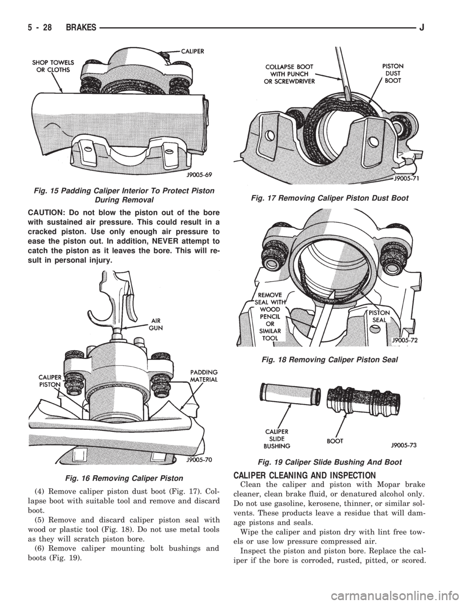
(2) Pad interior of caliper with minimum, 2.54 cm
(1 in.) thickness of shop towels or rags (Fig. 15). Tow-
els are needed to protect caliper piston during re-
moval.
(3) Remove caliper piston withshort burstsof low
pressure compressed air. Direct air through fluid in-
let port and ease piston out of bore (Fig. 16).
Fig. 11 Installing Inboard Brakeshoe
Fig. 12 Installing Outboard Brakeshoe
Fig. 13 Caliper Installation
Fig. 14 Caliper Mounting Bolt Dimensions
JBRAKES 5 - 27
Page 175 of 1784
CAUTION: Do not blow the piston out of the bore
with sustained air pressure. This could result in a
cracked piston. Use only enough air pressure to
ease the piston out. In addition, NEVER attempt to
catch the piston as it leaves the bore. This will re-
sult in personal injury.
(4) Remove caliper piston dust boot (Fig. 17). Col-
lapse boot with suitable tool and remove and discard
boot.
(5) Remove and discard caliper piston seal with
wood or plastic tool (Fig. 18). Do not use metal tools
as they will scratch piston bore.
(6) Remove caliper mounting bolt bushings and
boots (Fig. 19).
CALIPER CLEANING AND INSPECTION
Clean the caliper and piston with Mopar brake
cleaner, clean brake fluid, or denatured alcohol only.
Do not use gasoline, kerosene, thinner, or similar sol-
vents. These products leave a residue that will dam-
age pistons and seals.
Wipe the caliper and piston dry with lint free tow-
els or use low pressure compressed air.
Inspect the piston and piston bore. Replace the cal-
iper if the bore is corroded, rusted, pitted, or scored.
Fig. 15 Padding Caliper Interior To Protect Piston
During Removal
Fig. 16 Removing Caliper Piston
Fig. 17 Removing Caliper Piston Dust Boot
Fig. 18 Removing Caliper Piston Seal
Fig. 19 Caliper Slide Bushing And Boot
5 - 28 BRAKESJ
Page 191 of 1784
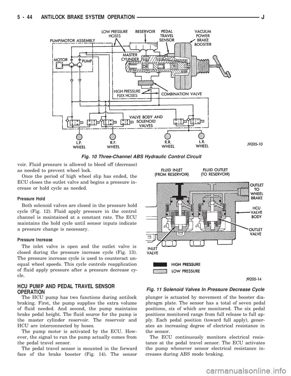
voir. Fluid pressure is allowed to bleed off (decrease)
as needed to prevent wheel lock.
Once the period of high wheel slip has ended, the
ECU closes the outlet valve and begins a pressure in-
crease or hold cycle as needed.
Pressure Hold
Both solenoid valves are closed in the pressure hold
cycle (Fig. 12). Fluid apply pressure in the control
channel is maintained at a constant rate. The ECU
maintains the hold cycle until sensor inputs indicate
a pressure change is necessary.
Pressure Increase
The inlet valve is open and the outlet valve is
closed during the pressure increase cycle (Fig. 13).
The pressure increase cycle is used to counteract un-
equal wheel speeds. This cycle controls reapplication
of fluid apply pressure after a pressure decrease cy-
cle.
HCU PUMP AND PEDAL TRAVEL SENSOR
OPERATION
The HCU pump has two functions during antilock
braking. First, the pump supplies the extra volume
of fluid needed. And second, the pump maintains
brake pedal height. The fluid source for the pump is
the master cylinder reservoir. The reservoir and
HCU are interconnected by hoses.
The pump motor is activated by the ECU. How-
ever, the signal to run the pump actually comes from
the pedal travel sensor.
The pedal travel sensor is mounted in the forward
face of the brake booster (Fig. 14). The sensorplunger is actuated by movement of the booster dia-
phragm plate. The sensor has a total of seven pedal
positions, six of which are monitored. The six pedal
positions monitored range from full release to full ap-
ply. Each pedal position (toward full apply), gener-
ates an increasing degree of electrical resistance in
the sensor.
The ECU continuously monitors electrical resis-
tance at the pedal travel sensor. The ECU activates
the pump whenever sensor electrical resistance in-
creases during ABS mode braking.
Fig. 10 Three-Channel ABS Hydraulic Control Circuit
Fig. 11 Solenoid Valves In Pressure Decrease Cycle
5 - 44 ANTILOCK BRAKE SYSTEM OPERATIONJ
Page 196 of 1784
Clean the reservoir and caps thoroughly before
checking level or adding fluid. Cap open lines and
hoses during service to prevent dirt entry.
Dirt or foreign material entering the ABS hydrau-
lic system through the reservoir opening will circu-
late within the system. The result will be poor brake
performance and possible component failure. Use
clean, fresh fluid only to top off, or refill the system.
WHEEL SENSOR AIR GAP ADJUSTMENT
Only rear sensor air gap is adjustable. The front
sensors are fixed and cannot be adjusted.
A rear sensor air gap adjustment is only
needed when reinstalling an original sensor. Re-
placement sensors have an air gap spacer at-
tached to the sensor pickup face. The spacer
establishes correct air gap when pressed against
the tone ring during installation. As the tone
ring rotates, it peels the spacer off the sensor to
create the required air gap.
Preferred rear sensor air gap is 1.1 mm (0.043 in.).
Acceptable air gap range is 0.92 to 1.275 mm (0.036
to 0.050 in.).
Front sensor air gap is not adjustable. The front
sensors are fixed in position and cannot be adjusted.
Front sensor air gap can only be checked. Air gap
should be 0.040 to 1.3 mm (0.0157 to 0.051 in.). If
front sensor air gap is incorrect, the sensor is either
loose, or damaged.
FRONT WHEEL SENSOR REMOVAL
(1) Raise vehicle and turn wheel outward for eas-
ier access to sensor.
(2) Remove sensor wire from mounting brackets.
(3) Clean sensor and surrounding area before removal.
(4) Remove bolt attaching sensor to steering
knuckle and remove sensor.
(5) Unseat grommet retaining sensor wire in wheel
house panel.
(6) In engine compartment, disconnect sensor wire con-
nector at harness plug. Then remove sensor and wire.
FRONT WHEEL SENSOR INSTALLATION
(1) Apply Mopar Lock N' Seal or Loctite 242 to
bolt that attaches sensor to steering knuckle. Use
new sensor bolt if original bolt is worn or damaged.
(2) Position sensor on steering knuckle. Seat sen-
sor locating tab in hole in knuckle and install sensor
attaching bolt finger tight.
(3) Tighten sensor bolt to 14 NIm (11 ft. lbs.) torque.
(4) Attach sensor wire to steering knuckle bracket
with grommets on sensor wire.
(5) Route sensor wire forward and behind shock
absorber. Then attach sensor wire to spring seat
bracket with grommets on sensor wire.
(6) Route sensor wire to outer sill bracket. Remove
all twists or kinks from wire.(7) Attach sensor wire to sill bracket with grom-
met. Be sure wire is free of twists and kinks.
(8) Verify sensor wire routing. Wire should loop
forward and above sill bracket. Loose end of wire
should be below sill bracket and towards brake hose.
(9) Seat sensor wire grommet in body panel and
clip wire to brake line at grommet location.
(10) Connect sensor wire to harness in engine com-
partment.
REAR WHEEL SENSOR REMOVAL
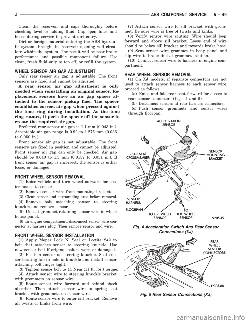
(1) On XJ models, if separate connectors are not
used to attach sensor harness to each sensor wire,
proceed as follows:
(a) Raise and fold rear seat forward for access to
rear sensor connectors (Figs. 4 and 5).
(b) Disconnect sensors at rear harness connectors.
(c) Push sensor grommets and sensor wires
through floorpan.
Fig. 4 Acceleration Switch And Rear Sensor
Connections (XJ)
Fig. 5 Rear Sensor Connections (XJ)
JABS COMPONENT SERVICE 5 - 49