1994 JEEP CHEROKEE tow
[x] Cancel search: towPage 331 of 1784

Check the high-tension cable connections for good
contact at the ignition coil, distributor cap towers
and spark plugs. Terminals should be fully seated.
The terminals and spark plug covers should be in
good condition. Terminals should fit tightly to the ig-
nition coil, distributor cap and spark plugs. The
spark plug cover (boot) of the cable should fit tight
around the spark plug insulator. Loose cable connec-
tions can cause corrosion and increase resistance, re-
sulting in shorter cable service life.
Clean the high tension cables with a cloth moist-
ened with a nonflammable solvent and wipe dry.
Check for brittle or cracked insulation.
When testing secondary cables for damage with an
oscilloscope, follow the instructions of the equipment
manufacturer.
If an oscilloscope is not available, spark plug cables
may be tested as follows:
CAUTION: Do not leave any one spark plug cable
disconnected for longer than necessary during test-
ing. This may cause possible heat damage to the
catalytic converter. Total test time must not exceed
ten minutes.
With the engine not running, connect one end of a
test probe to a good ground. Start the engine and run
the other end of the test probe along the entire
length of all spark plug cables. If cables are cracked
or punctured, there will be a noticeable spark jump
from the damaged area to the test probe. The cable
running from the ignition coil to the distributor cap
can be checked in the same manner. Cracked, dam-
aged or faulty cables should be replaced with resis-
tance type cable. This can be identified by the words
ELECTRONIC SUPPRESSION printed on the cable
jacket.
Use an ohmmeter to test for open circuits, exces-
sive resistance or loose terminals. Remove the dis-
tributor cap from the distributor.Do not remove
cables from cap.Remove cable from spark plug.
Connect ohmmeter to spark plug terminal end of ca-
ble and to corresponding electrode in distributor cap.
Resistance should be 250 to 1000 Ohms per inch of
cable. If not, remove cable from distributor cap tower
and connect ohmmeter to the terminal ends of cable.
If resistance is not within specifications as found in
the Spark Plug Cable Resistance chart, replace the
cable. Test all spark plug cables in this manner.To test ignition coil-to-distributor cap cable, do not
remove the cable from the cap. Connect ohmmeter to
rotor button (center contact) of distributor cap and
terminal at ignition coil end of cable. If resistance is
not within specifications as found in the Spark Plug
Cable Resistance chart, remove the cable from the
distributor cap. Connect the ohmmeter to the termi-
nal ends of the cable. If resistance is not within spec-
ifications as found in the Spark Plug Cable
Resistance chart, replace the cable. Inspect the igni-
tion coil tower for cracks, burns or corrosion.
For removal and installation of spark plug cables,
refer to Spark Plug Secondary Cables in the Compo-
nent Removal/Installation section.
THROTTLE POSITION SENSOR TEST
To perform a complete test of this sensor and its
circuitry, refer to the DRB scan tool. Also refer to the
appropriate Powertrain Diagnostics Procedures man-
ual. To test the sensor only, refer to the following:
The throttle position sensor can be tested with a
digital voltmeter. The center terminal of the sensor
connector is the output terminal (Figs. 30 or 31).
SPARK PLUG CABLE RESISTANCE
Fig. 30 SensorÐ2.5L Engine
Fig. 31 SensorÐ4.0L Engine
8D - 18 IGNITION SYSTEMSJ
Page 342 of 1784
cleaning, file the center electrode flat with a small
point file or jewelers file before adjusting gap.
PLUG GAP ADJUSTMENT
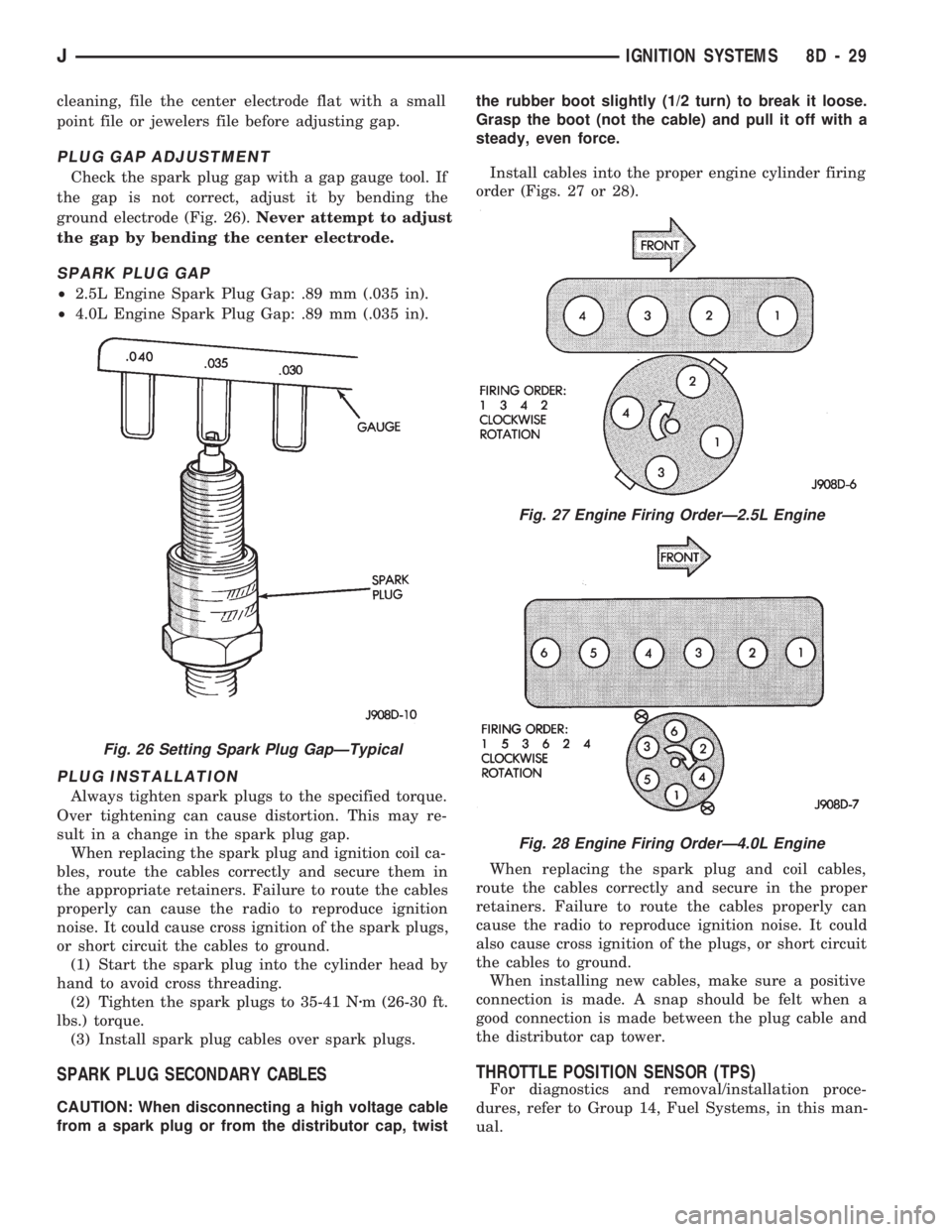
Check the spark plug gap with a gap gauge tool. If
the gap is not correct, adjust it by bending the
ground electrode (Fig. 26).Never attempt to adjust
the gap by bending the center electrode.
SPARK PLUG GAP
²2.5L Engine Spark Plug Gap: .89 mm (.035 in).
²4.0L Engine Spark Plug Gap: .89 mm (.035 in).
PLUG INSTALLATION
Always tighten spark plugs to the specified torque.
Over tightening can cause distortion. This may re-
sult in a change in the spark plug gap.
When replacing the spark plug and ignition coil ca-
bles, route the cables correctly and secure them in
the appropriate retainers. Failure to route the cables
properly can cause the radio to reproduce ignition
noise. It could cause cross ignition of the spark plugs,
or short circuit the cables to ground.
(1) Start the spark plug into the cylinder head by
hand to avoid cross threading.
(2) Tighten the spark plugs to 35-41 Nzm (26-30 ft.
lbs.) torque.
(3) Install spark plug cables over spark plugs.
SPARK PLUG SECONDARY CABLES
CAUTION: When disconnecting a high voltage cable
from a spark plug or from the distributor cap, twistthe rubber boot slightly (1/2 turn) to break it loose.
Grasp the boot (not the cable) and pull it off with a
steady, even force.
Install cables into the proper engine cylinder firing
order (Figs. 27 or 28).
When replacing the spark plug and coil cables,
route the cables correctly and secure in the proper
retainers. Failure to route the cables properly can
cause the radio to reproduce ignition noise. It could
also cause cross ignition of the plugs, or short circuit
the cables to ground.
When installing new cables, make sure a positive
connection is made. A snap should be felt when a
good connection is made between the plug cable and
the distributor cap tower.
THROTTLE POSITION SENSOR (TPS)
For diagnostics and removal/installation proce-
dures, refer to Group 14, Fuel Systems, in this man-
ual.
Fig. 26 Setting Spark Plug GapÐTypical
Fig. 27 Engine Firing OrderÐ2.5L Engine
Fig. 28 Engine Firing OrderÐ4.0L Engine
JIGNITION SYSTEMS 8D - 29
Page 344 of 1784
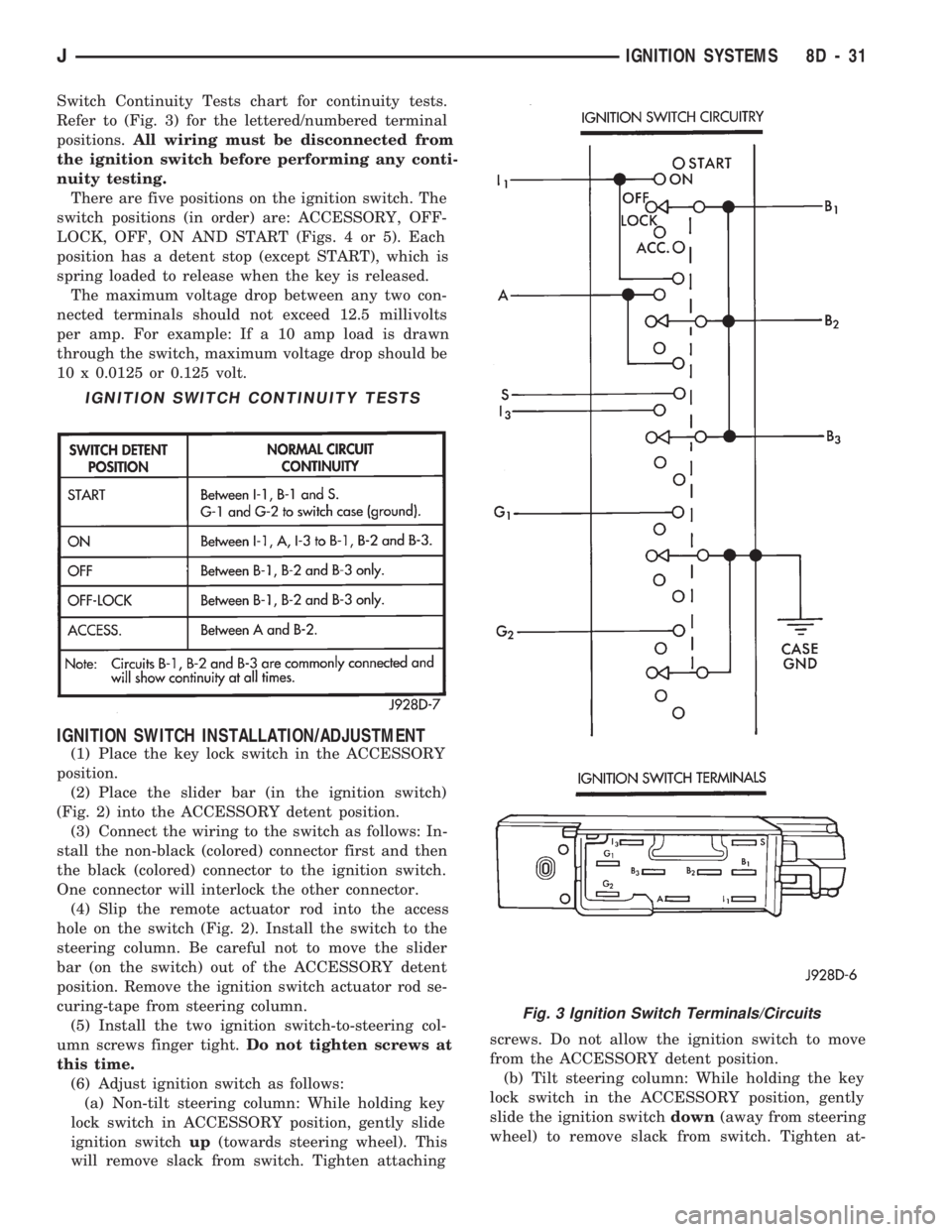
Switch Continuity Tests chart for continuity tests.
Refer to (Fig. 3) for the lettered/numbered terminal
positions.All wiring must be disconnected from
the ignition switch before performing any conti-
nuity testing.
There are five positions on the ignition switch. The
switch positions (in order) are: ACCESSORY, OFF-
LOCK, OFF, ON AND START (Figs. 4 or 5). Each
position has a detent stop (except START), which is
spring loaded to release when the key is released.
The maximum voltage drop between any two con-
nected terminals should not exceed 12.5 millivolts
per amp. For example: If a 10 amp load is drawn
through the switch, maximum voltage drop should be
10 x 0.0125 or 0.125 volt.
IGNITION SWITCH INSTALLATION/ADJUSTMENT
(1) Place the key lock switch in the ACCESSORY
position.
(2) Place the slider bar (in the ignition switch)
(Fig. 2) into the ACCESSORY detent position.
(3) Connect the wiring to the switch as follows: In-
stall the non-black (colored) connector first and then
the black (colored) connector to the ignition switch.
One connector will interlock the other connector.
(4) Slip the remote actuator rod into the access
hole on the switch (Fig. 2). Install the switch to the
steering column. Be careful not to move the slider
bar (on the switch) out of the ACCESSORY detent
position. Remove the ignition switch actuator rod se-
curing-tape from steering column.
(5) Install the two ignition switch-to-steering col-
umn screws finger tight.Do not tighten screws at
this time.
(6) Adjust ignition switch as follows:
(a) Non-tilt steering column: While holding key
lock switch in ACCESSORY position, gently slide
ignition switchup(towards steering wheel). This
will remove slack from switch. Tighten attachingscrews. Do not allow the ignition switch to move
from the ACCESSORY detent position.
(b) Tilt steering column: While holding the key
lock switch in the ACCESSORY position, gently
slide the ignition switchdown(away from steering
wheel) to remove slack from switch. Tighten at-
IGNITION SWITCH CONTINUITY TESTS
Fig. 3 Ignition Switch Terminals/Circuits
JIGNITION SYSTEMS 8D - 31
Page 345 of 1784

taching screws. Do not allow the ignition switch to
move from the ACCESSORY detent position.
Because the ignition switch and the headlamp dim-
mer switch share the same two mounting screws, one
of the screws must be removed from the ignition
switch. This must be doneafterthe ignition switch
has been adjusted andbeforethe dimmer switch has
been installed. Remove one screw.Do notremove
the stud/nut.
(7) Install the headlamp dimmer switch as follows:
Slip switch into actuator rod and position over the ig-
nition switch. Install screws finger tight. Remove the
dimmer switch actuator rod securing-tape from steer-
ing column.
(8) Adjust dimmer switch as follows: Depress the
switch slightly and insert a 3/32-inch drill bit into
the adjustment hole (Fig. 1). This is done to prevent
horizontal switch movement.
(9) Move switch toward steering wheel to remove
any lash from switch actuator rod. Tighten dimmer
and ignition switch fasteners to 4 Nzm (35 in. lbs.)
torque.
(10) XJ models: Install the lower instrument panel
trim assembly. YJ models: Install the windshield
wiper intermittent control module and its bracket (if
equipped).
(11) Install the negative battery cable.
Test dimmer switch. Test ignition switch operation
in all switch positions. If equipped with a tilt steer-
ing column, test operation of dimmer switch and ig-
nition switch in all tilt positions.
Fig. 4 Detent PositionsÐNon-Tilt Steering Column
Fig. 5 Detent PositionsÐTilt Steering Column
8D - 32 IGNITION SYSTEMSJ
Page 364 of 1784

INSTRUMENT CLUSTER SERVICE PROCEDURES
INDEX
page page
Headlamp Switch/Illumination Rheostat........ 21
Indicator Bezel Replacement................ 17
Instrument Cluster Bulb Replacement......... 19
Instrument Cluster Replacement............. 17Printed Circuit Replacement................ 19
Rear Defogger/Fog Lamp/Rear Wiper Switches . . 21
Speedometer Replacement................. 17
Tachometer Replacement.................. 17
INSTRUMENT CLUSTER REPLACEMENT
(1) Remove 6 shroud screws (Fig. 1).
(2) Slide shroud toward steering wheel.
(3) Remove 3 screws holding right side switch
panel (Fig. 2).
(4) Remove 3 screws holding left side switch bezel.(5) Remove 2 screws holding cluster in place.
(6) Lift up top of cluster. Roll cluster out between
steering column and instrument panel far enough to
reach connector located behind tachometer.
(7) Disconnect cluster connector and remove clus-
ter (Fig. 3).
(8) To install cluster, reverse the removal proce-
dures.
TACHOMETER REPLACEMENT
(1) Disconnect negative cable from battery.
(2) Remove instrumentation shroud (Fig. 1). Refer
to Instrument Cluster Replacement.
(3) Remove cluster as described in Instrument
Cluster replacement.
(4) Remove 3 screws and tachometer lens (Fig. 4).
(5) Gently pry up clip to release lens from bezel
(Fig. 5).
(6) Remove 3 screws from rear of housing (Fig. 6).
Remove tachometer.
(7) Install tachometer with 3 screws.
(8) Snap lens into place.
(9) Install lens with 3 screws.
(10) To install the cluster, reverse the removal pro-
cedures.
SPEEDOMETER REPLACEMENT
(1) Disconnect negative cable from battery.
(2) Remove instrument shroud (Fig. 1). Refer to In-
strument Cluster Replacement.
(3) Remove cluster as described in Instrument
Cluster Replacement.
(4) Remove 3 screws and speedometer lens (Fig. 7).
(5) Gently pry up clip to release lens from bezel
(Fig. 5).
(6) Remove 3 screws from rear of housing (Fig. 8).
Remove speedometer.
(7) Install speedometer with 3 screws.
(8) Snap lens into place.
(9) Install lens with 3 screws.
(10) To install the cluster, reverse the removal pro-
cedures.
INDICATOR BEZEL REPLACEMENT
(1) Disconnect negative cable from battery.
(2) Remove instrumentation shroud (Fig. 1).
(3) Remove 3 screws and tachometer lens (Fig. 4).
Fig. 2 Cluster Removal
Fig. 1 Instrument Shroud Removal/Installation
JYJ INSTRUMENT PANEL AND GAUGES 8E - 17
Page 367 of 1784
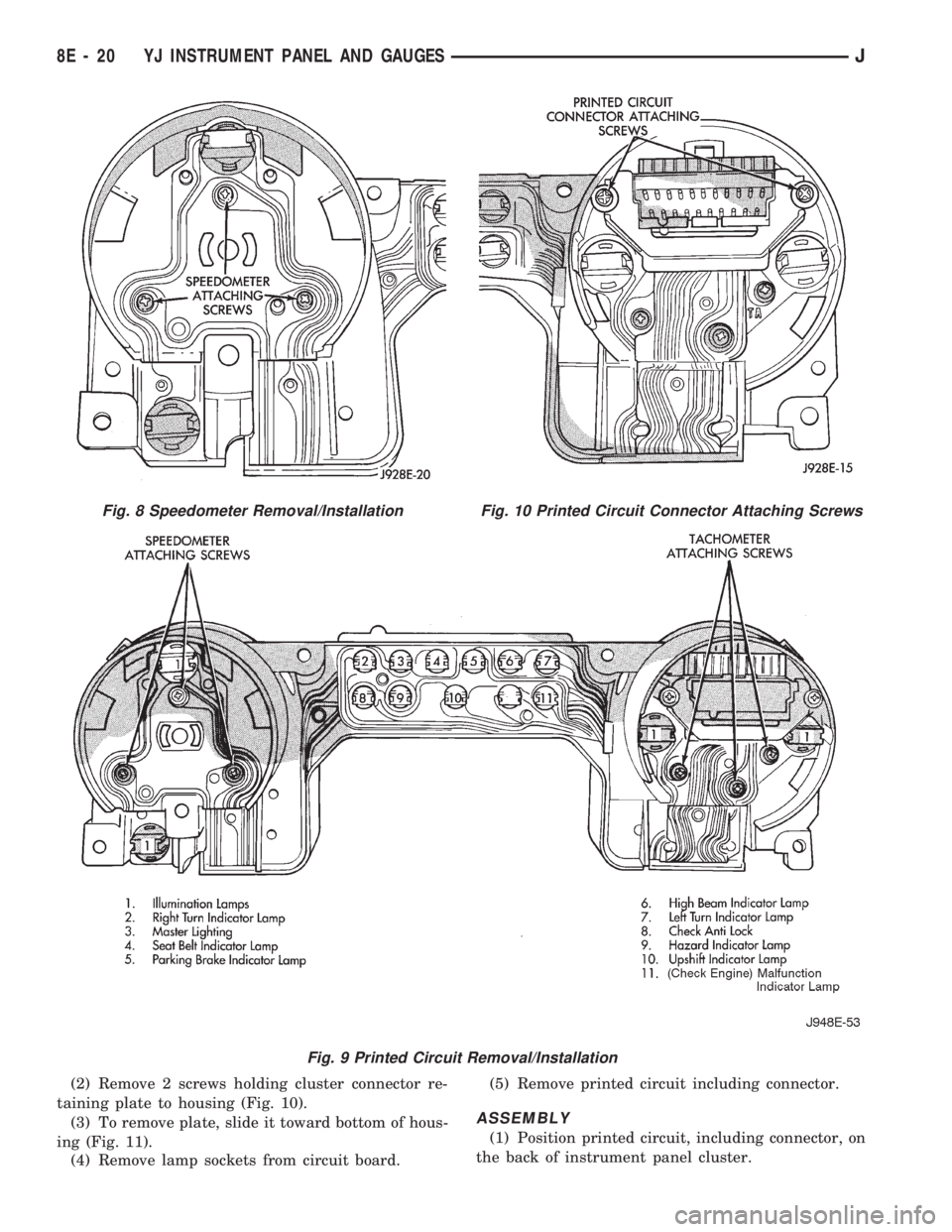
(2) Remove 2 screws holding cluster connector re-
taining plate to housing (Fig. 10).
(3) To remove plate, slide it toward bottom of hous-
ing (Fig. 11).
(4) Remove lamp sockets from circuit board.(5) Remove printed circuit including connector.
ASSEMBLY
(1) Position printed circuit, including connector, on
the back of instrument panel cluster.
Fig. 8 Speedometer Removal/Installation
Fig. 9 Printed Circuit Removal/Installation
Fig. 10 Printed Circuit Connector Attaching Screws
8E - 20 YJ INSTRUMENT PANEL AND GAUGESJ
Page 371 of 1784
GAUGE PACKAGE SERVICE PROCEDURES
PRINTED CIRCUIT REMOVAL
DISASSEMBLY
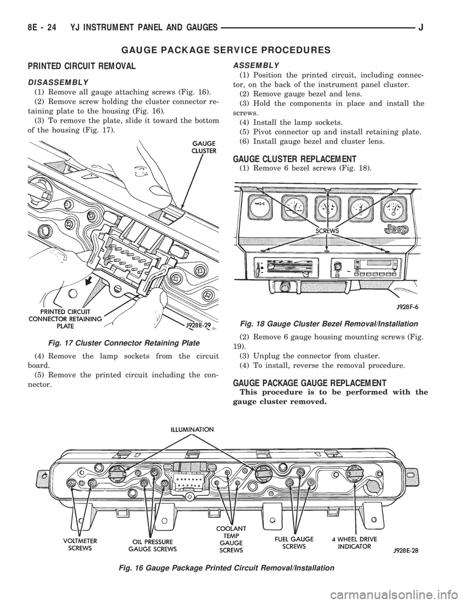
(1) Remove all gauge attaching screws (Fig. 16).
(2) Remove screw holding the cluster connector re-
taining plate to the housing (Fig. 16).
(3) To remove the plate, slide it toward the bottom
of the housing (Fig. 17).
(4) Remove the lamp sockets from the circuit
board.
(5) Remove the printed circuit including the con-
nector.
ASSEMBLY
(1) Position the printed circuit, including connec-
tor, on the back of the instrument panel cluster.
(2) Remove gauge bezel and lens.
(3) Hold the components in place and install the
screws.
(4) Install the lamp sockets.
(5) Pivot connector up and install retaining plate.
(6) Install gauge bezel and cluster lens.
GAUGE CLUSTER REPLACEMENT
(1) Remove 6 bezel screws (Fig. 18).
(2) Remove 6 gauge housing mounting screws (Fig.
19).
(3) Unplug the connector from cluster.
(4) To install, reverse the removal procedure.
GAUGE PACKAGE GAUGE REPLACEMENT
This procedure is to be performed with the
gauge cluster removed.
Fig. 16 Gauge Package Printed Circuit Removal/Installation
Fig. 17 Cluster Connector Retaining Plate
Fig. 18 Gauge Cluster Bezel Removal/Installation
8E - 24 YJ INSTRUMENT PANEL AND GAUGESJ
Page 394 of 1784
TEST PROCEDURES
INDEX
page page
Checking for Diagnostic Trouble Code......... 5
Electrical Tests at Powertrain Control Module.... 6
Electrical Tests at Servo.................... 5
Inoperative System........................ 5
Operational Check (Road Test)............... 7
Road Test............................... 5Speed Control Switch (Turn Signal Lever) Test . . . 7
Stop Lamp Speed Control Switch Test......... 7
Vacuum Supply Test....................... 7
Vehicle Speed Control System Electrical Tests . . . 5
Vehicle Speed Sensor Test.................. 5
ROAD TEST
Refer to Operational Check (Road Test) section to
verify reports of speed control system malfunction.
INOPERATIVE SYSTEM
Road test vehicle to verify reports of speed control
system malfunction. An inspection should be made
for loose electrical and vacuum connections at the
servo.
Check for correct installation of the vacuum check
valve in the hose from servo to vacuum source. The
word VAC on the valve must point toward the vac-
uum source.
Corrosion should be removed from electrical termi-
nals and a light coating of Mopar MultiPurpose
Grease, or equivalent, applied.
Inspection also should be made to verify that both
ends of the speed control cable are securely attached.
CHECKING FOR DIAGNOSTIC TROUBLE CODE
(1) When trying to verify a speed control system
electronic malfunction use a DRB scan tool to find
the cause (refer to Powertrain Diagnostic Procedures
manual).
If DRB is not available, the Diagnostic Trouble
Code (DTC) may be determined with the following
method:
(a) With key inserted in ignition switch, cycle
switch to ON position 3 times. On third cycle, leave
switch in ON position.
(b) After switch has been cycled 3 times, observe
Malfunction Indicator Lamp (CHECK ENGINE)
on instrument cluster. If a DTC is present, the code
will be displayed in a series of flashes representing
digits. Three flashes in rapid succession, a slight
pause, then 4 flashes in rapid succession would in-
dicate DTC 34.
(2) If a DTC 34 is observed, perform tests in the
sections Electrical Tests at Servo and Electrical Tests
at Powertrain Control Module.
If a DTC 15 is observed, perform test for a faulty
vehicle speed sensor.
(3) Correct any problems found when performing
these tests and recheck for DTC if changes were
made.
VEHICLE SPEED SENSOR TEST
For testing of the vehicle speed sensor and related
components, refer to Powertrain Diagnostic Proce-
dures manual.
VEHICLE SPEED CONTROL SYSTEM ELECTRICAL
TESTS
Vehicle speed control systems may be tested using
two different methods. One involves use of a DRB
scan tool. If this test method is desired, refer to Pow-
ertrain Diagnostic Procedures manual.
The other test method uses a voltmeter. The volt-
meter method is described in the following tests.
If any information is needed concerning wiring, re-
fer to Section 8W - Wiring Diagrams.
CAUTION: When test probing for voltage or conti-
nuity at electrical connectors, care must be taken
not to damage connector, terminals, or seals. If
these components are damaged, intermittent or
complete system failure may occur.
ELECTRICAL TESTS AT SERVO
(1) Turn ignition switch to the ON position. With
speed control switch in the ON position, setup a volt-
meter to read battery voltage and connect negative
lead to a good chassis ground.
(2) Disconnect 4-way connector going to servo
(Figs. 2 and 3). Blue wire with red tracer of main
harness 4-way connector should read approximately
battery voltage. If not, check for loose connections,
brake switch adjustment or, repair main harness as
necessary.
(3) Connect a jumper wire between male and fe-
male terminals of blue wire with red tracer. The
other 3 male terminals from servo should show bat-
tery voltage. If not, replace servo.
(4) Using an ohmmeter, connect one lead to a good
body ground. Touch other lead to black wire terminal
in 4-way connector of main harness. Meter should
show continuity. If not, repair ground circuit as nec-
essary.
JVEHICLE SPEED CONTROL SYSTEM 8H - 5