1994 JEEP CHEROKEE tow
[x] Cancel search: towPage 405 of 1784

(a) Remove 6 housing screws (Fig. 4).
(b) Slide housing toward steering wheel.
(18) Remove cover under column.
(19) If vehicle is equipped with a column shift, re-
move PRNDL cable clip (Fig. 5).
(20) Remove 2 nuts holding steering column
bracket to brake sled (Fig. 6).
(21) Remove 4 bolts holding steering column
bracket to column.
(22) Loosen column brace mounting nut at drivers
side kick panel. This will allow column to drop.(23) Push turn/hazard connector up and out of
steering column connector (Fig. 7).
(24) Pry up locking tabs of steering column connec-
tor and remove connector from column bracket.
(25) Tape connector to wires as shown (Fig. 8).
(26) Remove plastic harness cover by pulling it up
and over the weld nuts then open and slide the cover
off the harness (Fig. 9).
Fig. 4 Instrument Housing Removal/InstallationÐYJ
Fig. 5 PRNDL Cable Clip Removal/Installation
Fig. 6 Lower Steering Column
Fig. 7 Turn/Hazard Switch And Steering Column
Connectors
8J - 4 TURN SIGNALS AND HAZARD WARNING FLASHERJ
Page 423 of 1784
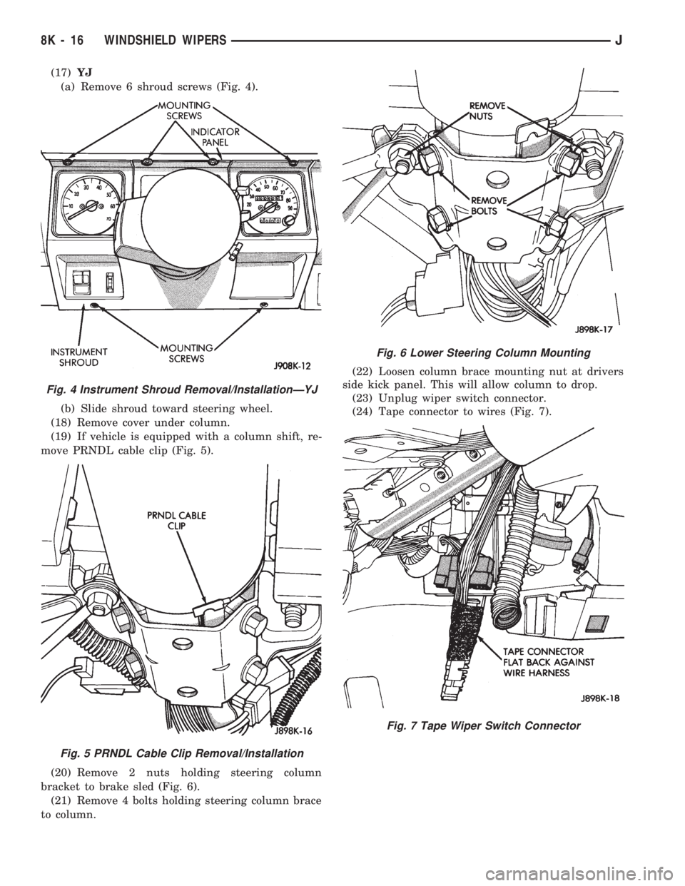
(17)YJ
(a) Remove 6 shroud screws (Fig. 4).
(b) Slide shroud toward steering wheel.
(18) Remove cover under column.
(19) If vehicle is equipped with a column shift, re-
move PRNDL cable clip (Fig. 5).
(20) Remove 2 nuts holding steering column
bracket to brake sled (Fig. 6).
(21) Remove 4 bolts holding steering column brace
to column.(22) Loosen column brace mounting nut at drivers
side kick panel. This will allow column to drop.
(23) Unplug wiper switch connector.
(24) Tape connector to wires (Fig. 7).
Fig. 4 Instrument Shroud Removal/InstallationÐYJ
Fig. 5 PRNDL Cable Clip Removal/Installation
Fig. 6 Lower Steering Column Mounting
Fig. 7 Tape Wiper Switch Connector
8K - 16 WINDSHIELD WIPERSJ
Page 432 of 1784
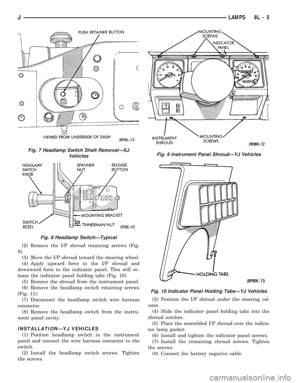
(2) Remove the I/P shroud retaining screws (Fig.
9).
(3) Move the I/P shroud toward the steering wheel.
(4) Apply upward force to the I/P shroud and
downward force to the indicator panel. This will re-
lease the indicator panel holding tabs (Fig. 10).
(5) Remove the shroud from the instrument panel.
(6) Remove the headlamp switch retaining screws
(Fig. 11).
(7) Disconnect the headlamp switch wire harness
connector.
(8) Remove the headlamp switch from the instru-
ment panel cavity.
INSTALLATIONÐYJ VEHICLES
(1) Position headlamp switch in the instrument
panel and connect the wire harness connector to the
switch.
(2) Install the headlamp switch screws. Tighten
the screws.(3) Position the I/P shroud under the steering col-
umn.
(4) Slide the indicator panel holding tabs into the
shroud notches.
(5) Place the assembled I/P shroud over the indica-
tor lamp gasket.
(6) Install and tighten the indicator panel screws.
(7) Install the remaining shroud screws. Tighten
the screws.
(8) Connect the battery negative cable.
Fig. 7 Headlamp Switch Shaft RemovalÐXJ
Vehicles
Fig. 8 Headlamp SwitchÐTypical
Fig. 9 Instrument Panel ShroudÐYJ Vehicles
Fig. 10 Indicator Panel Holding TabsÐYJ Vehicles
JLAMPS 8L - 5
Page 433 of 1784
HEADLAMP DIMMER SWITCH REPLACEMENT
REMOVAL
(1) Disconnect battery negative cable.
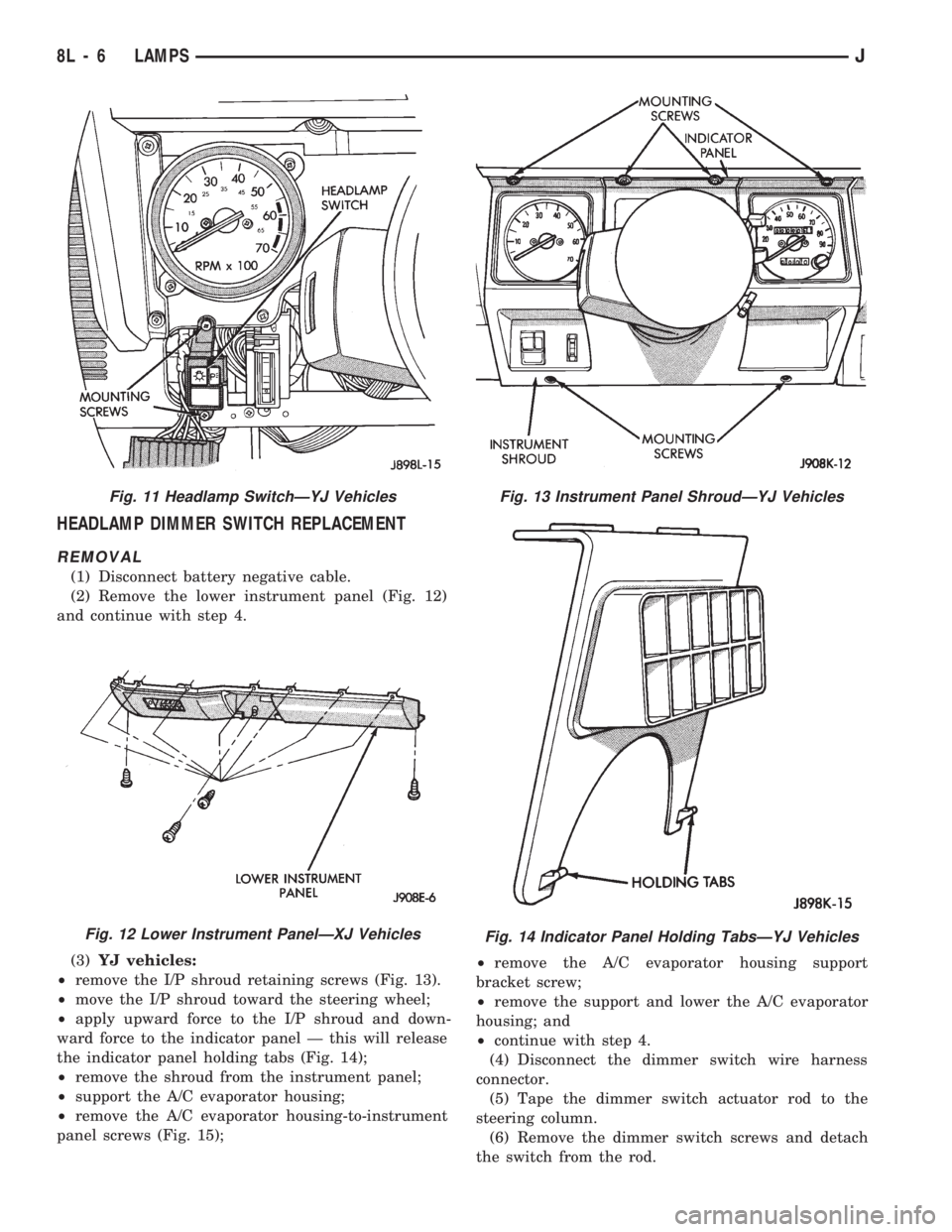
(2) Remove the lower instrument panel (Fig. 12)
and continue with step 4.
(3)YJ vehicles:
²remove the I/P shroud retaining screws (Fig. 13).
²move the I/P shroud toward the steering wheel;
²apply upward force to the I/P shroud and down-
ward force to the indicator panel Ð this will release
the indicator panel holding tabs (Fig. 14);
²remove the shroud from the instrument panel;
²support the A/C evaporator housing;
²remove the A/C evaporator housing-to-instrument
panel screws (Fig. 15);²remove the A/C evaporator housing support
bracket screw;
²remove the support and lower the A/C evaporator
housing; and
²continue with step 4.
(4) Disconnect the dimmer switch wire harness
connector.
(5) Tape the dimmer switch actuator rod to the
steering column.
(6) Remove the dimmer switch screws and detach
the switch from the rod.
Fig. 11 Headlamp SwitchÐYJ Vehicles
Fig. 12 Lower Instrument PanelÐXJ Vehicles
Fig. 13 Instrument Panel ShroudÐYJ Vehicles
Fig. 14 Indicator Panel Holding TabsÐYJ Vehicles
8L - 6 LAMPSJ
Page 434 of 1784
INSTALLATION
(1) Force the dimmer switch onto the actuator rod
and install screws.DO NOT tighten the retaining
screws at this time.
(2) Remove the tape attaching the actuator rod to
the steering column.
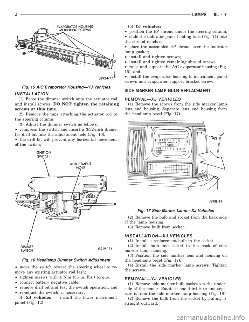
(3) Adjust the dimmer switch as follows:
²compress the switch and insert a 3/32-inch diame-
ter drill bit into the adjustment hole (Fig. 16);
²the drill bit will prevent any horizontal movement
of the switch;
²move the switch toward the steering wheel to re-
move any existing actuator rod lash;
²tighten screws with 4 Nzm (35 in. lbs.) torque.
²connect battery negative cable;
²remove drill bit and test the switch operation; and
²re-adjust the switch, if necessary.
(4)XJ vehiclesÐ install the lower instrument
panel (Fig. 12)(5)YJ vehicles:
²position the I/P shroud under the steering column;
²slide the indicator panel holding tabs (Fig. 14) into
the shroud notches;
²place the assembled I/P shroud over the indicator
lamp gasket;
²install and tighten screws;
²install and tighten remaining shroud screws;
²raise and support the A/C evaporator housing (Fig.
15); and
²install the evaporator housing-to-instrument panel
screws and evaporator support bracket screw.
SIDE MARKER LAMP BULB REPLACEMENT
REMOVALÐXJ VEHICLES
(1) Remove the screws from the side marker lamp
lens and housing. Separate lens and housing from
the headlamp bezel (Fig. 17).
(2) Remove the bulb and socket from the back side
of the lamp housing.
(3) Remove bulb from socket.
INSTALLATIONÐXJ VEHICLES
(1) Install a replacement bulb in the socket.
(2) Install bulb and socket in the back of side
marker lamp housing.
(3) Position the side marker lens and housing on
the headlamp bezel (Fig. 17).
(4) Install the side marker lamp screws. Tighten
the screws.
REMOVALÐYJ VEHICLES
(1) Remove side marker bulb socket via the under-
side of the fender. Rotate it one-third turn and sepa-
rate it from the side marker lamp housing (Fig. 18).
(2) Remove the bulb from the socket by pulling it
straight outward.
Fig. 15 A/C Evaporator HousingÐYJ Vehicles
Fig. 16 Headlamp Dimmer Switch Adjustment
Fig. 17 Side Marker LampÐXJ Vehicles
JLAMPS 8L - 7
Page 441 of 1784
(3) For XJ vehicles, position the bezel and the lens
on the lamp housing. Install the screws that attach
the bezel and lens to the lamp housing. Tighten the
screws securely.
(4) For YJ vehicles, position the stone shield and
reflector on the lamp housing. Install the screws that
attach the stone shield and the reflector to the lamp
housing. Tighten the screws securely.
FOG LAMP SWITCH REPLACEMENT
REMOVALÐXJ VEHICLES
The fog lamp switch is located on the instrument
panel at the left of the steering column.
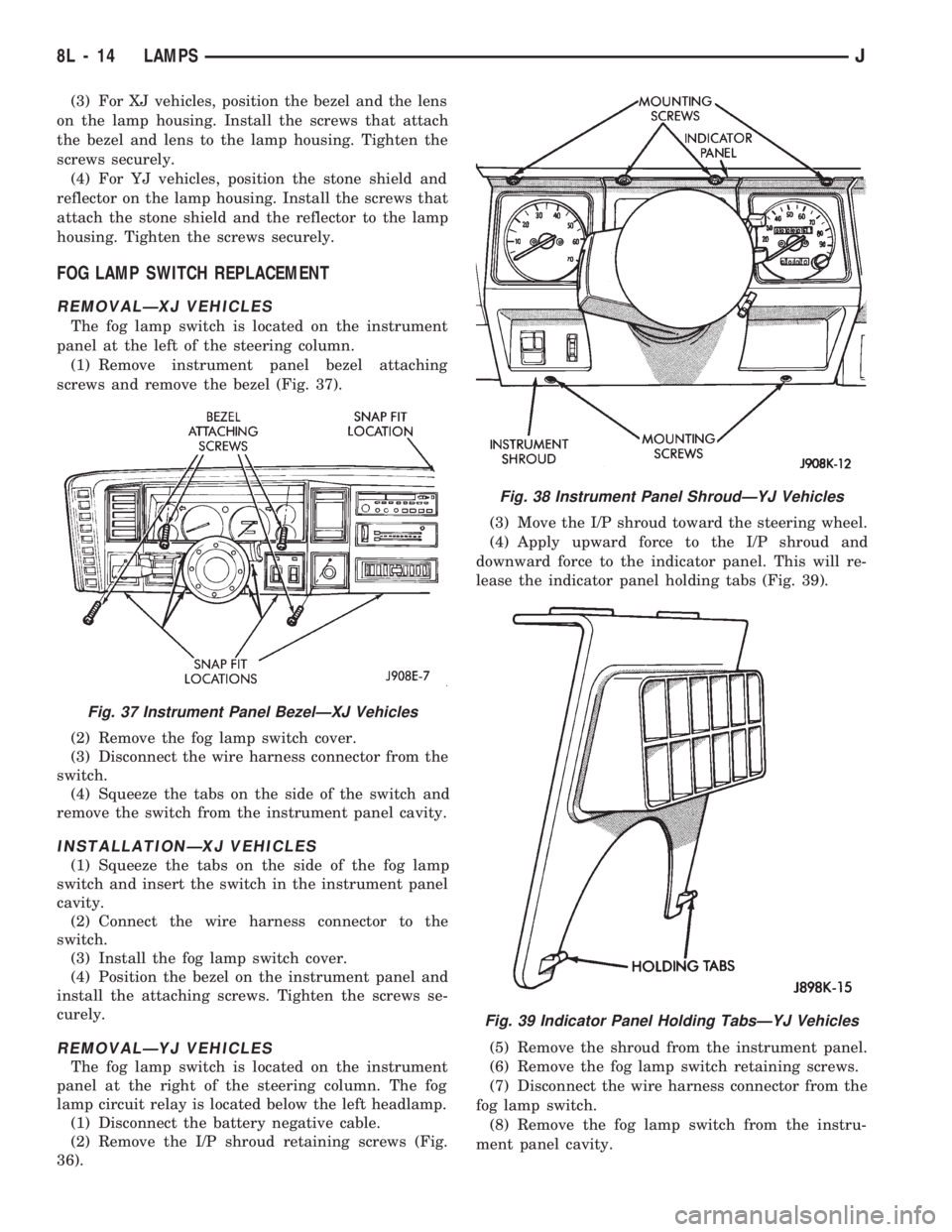
(1) Remove instrument panel bezel attaching
screws and remove the bezel (Fig. 37).
(2) Remove the fog lamp switch cover.
(3) Disconnect the wire harness connector from the
switch.
(4) Squeeze the tabs on the side of the switch and
remove the switch from the instrument panel cavity.
INSTALLATIONÐXJ VEHICLES
(1) Squeeze the tabs on the side of the fog lamp
switch and insert the switch in the instrument panel
cavity.
(2) Connect the wire harness connector to the
switch.
(3) Install the fog lamp switch cover.
(4) Position the bezel on the instrument panel and
install the attaching screws. Tighten the screws se-
curely.
REMOVALÐYJ VEHICLES
The fog lamp switch is located on the instrument
panel at the right of the steering column. The fog
lamp circuit relay is located below the left headlamp.
(1) Disconnect the battery negative cable.
(2) Remove the I/P shroud retaining screws (Fig.
36).(3) Move the I/P shroud toward the steering wheel.
(4) Apply upward force to the I/P shroud and
downward force to the indicator panel. This will re-
lease the indicator panel holding tabs (Fig. 39).
(5) Remove the shroud from the instrument panel.
(6) Remove the fog lamp switch retaining screws.
(7) Disconnect the wire harness connector from the
fog lamp switch.
(8) Remove the fog lamp switch from the instru-
ment panel cavity.
Fig. 37 Instrument Panel BezelÐXJ Vehicles
Fig. 38 Instrument Panel ShroudÐYJ Vehicles
Fig. 39 Indicator Panel Holding TabsÐYJ Vehicles
8L - 14 LAMPSJ
Page 455 of 1784
XJ
REAR WINDOW DEFOGGER SWITCH
REPLACEMENT
(1) Remove the instrument panel bezel; see 8E-In-
strument Panel and Gauges section for the proce-
dure.
(2) Remove the switch housing panel.
(3) Unplug the switch connector. Slightly depress
the switch mounting tabs and remove the switch.
REAR DEFOGGER RELAY
The rear defogger relay is in the relay center. The
relay center is located on the lower instrument panel
trim cover just right of the steering column.
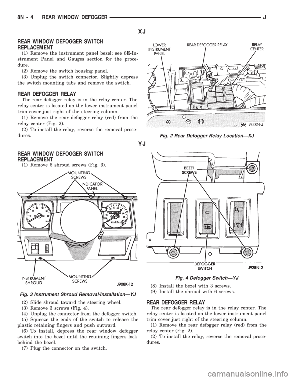
(1) Remove the rear defogger relay (red) from the
relay center (Fig. 2).
(2) To install the relay, reverse the removal proce-
dures.
YJ
REAR WINDOW DEFOGGER SWITCH
REPLACEMENT
(1) Remove 6 shroud screws (Fig. 3).
(2) Slide shroud toward the steering wheel.
(3) Remove 3 screws (Fig. 4).
(4) Unplug the connector from the defogger switch.
(5) Squeeze the ends of the switch to release the
plastic retaining fingers and push outward.
(6) To install, depress the rear window defogger
switch into the bezel until the retaining fingers lock
behind the bezel.
(7) Plug the connector on the switch.(8) Install the bezel with 3 screws.
(9) Install the shroud with 6 screws.
REAR DEFOGGER RELAY
The rear defogger relay is in the relay center. The
relay center is located on the lower instrument panel
trim cover just right of the steering column.
(1) Remove the rear defogger relay (red) from the
relay center (Fig. 2).
(2) To install the relay, reverse the removal proce-
dures.
Fig. 2 Rear Defogger Relay LocationÐXJ
Fig. 3 Instrument Shroud Removal/InstallationÐYJ
Fig. 4 Defogger SwitchÐYJ
8N - 4 REAR WINDOW DEFOGGERJ
Page 464 of 1784
code received matches the code in the receiver memory
circuit, the receiver triggers the door lock/unlock relays.
The relays complete the circuit to the electric door lock
solenoid to either lock or unlock the doors.
SYSTEM OPERATION
To activate the system, aim the transmitter diode
toward the receiver and press the transmitter signal
button to lock or unlock the doors as desired.
Effective transmitter range is 4.75 meters (15 ft.)
with the transmitter positioned no more than 45 de-
grees from the receiver centerline.
For complete circuit diagrams refer to Group
8W - Wiring Diagrams.
TRANSMITTER PROGRAMMING
Up to 4 Transmitter Identification Codes (TIC's) can
be programed into the receiver at any given time.
(1) Open the driver's door of the vehicle. Leave it
open through the programming procedure.
(2) Move the mechanical door lock lever to the
LOCK position.
(3) Turn the ignition switch to the ON position.
(4) Within 20 seconds, aim a transmitter at the re-
ceiver dome and press the LOCK button for at least
5 seconds. Once the receiver accepts the program-
ming code, the driver's door will unlock.
(5) Once the first transmitter has been pro-
grammed, additional transmitters (up to 4) may be
programmed into the receiver. Within 20 seconds of
the previous transmitter programming, move the me-
chanical door lock lever to the LOCK position. Aimanother transmitter at the receiver dome and press
the LOCK button for at least 5 seconds. The door
lock will cycle again.
(6) To lock the programmed codes into the re-
ceiver, the ignition switch must be turned OFF and
back ON within 20 seconds after programming the
last transmitter's code. At that time, all previous
codes are erased from the module.
DIAGNOSING POWER DOOR LOCKS
NO DOOR LOCKS OPERATE, USING
TRANSMITTER
(1) Measure resistance at keyless entry module
terminal 10. Meter should read zero ohms. If not, re-
pair open to ground.
(2) Measure voltage at keyless entry module termi-
nal 1. Meter should read battery voltage.Battery
voltage must be at least 9 volts for this system to
operate.If not, repair open to #9 fuse.
(3) Jumper test leads keyless entry module termi-
nal 1 to terminal 3. Doors should lock. If OK, replace
module. If not, repair open from terminal 3 to lock
relay terminal 1.
(4) Jumper test leads keyless entry module termi-
nal 1 to terminal 4. Door should unlock. If OK, re-
place module. If not, repair open from terminal 4 to
unlock relay terminal 1.
TRANSMITTER SERVICE
If the receiver malfunctions, only the receiver will
have to be replaced. The new receiver will have to be
reprogrammed. If a transmitter is lost, replace the
transmitter and reprogram the receiver.
Batteries may not be supplied with some re-
placement transmitters. Be sure to check a re-
placement transmitter before attempting to
activate the system.
TRANSMITTER BATTERY REPLACEMENT
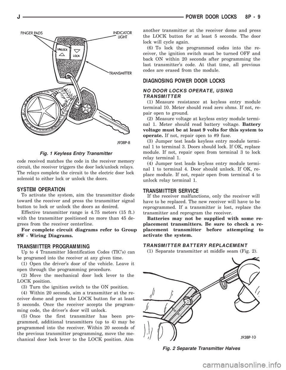
(1) Separate transmitter at middle seam (Fig. 2).
Fig. 2 Separate Transmitter Halves
Fig. 1 Keyless Entry Transmitter
JPOWER DOOR LOCKS 8P - 9