1994 JEEP CHEROKEE recommended oil
[x] Cancel search: recommended oilPage 1229 of 1784
OVERHAUL SERVICE INFORMATION
Inspect the transmission bushings during overhaul.
Bushing condition is important as severely worn, or
scored bushings contribute to low pressures, clutch
slip and accelerated wear of other components.How-
ever, do not replace bushings as a matter of
course. Replace bushings only when they are
actually worn, or scored.
Use recommended tools to replace bushings. The
tools are sized and designed to remove, install and
seat bushings correctly. The bushing replacement
tools are included in Bushing Tool Set C-3887-B. The
tool set is manufactured by Miller Tool Co. and is
available through the dealer tool program.
Pre-sized service bushings are available for replace-
ment purposes. Only the sun gear bushings are not
serviced. Low cost of the sun gear assembly makes it
easier to simply replace the gear and bushings as an
assembly.
Heli-Coil inserts are recommended for repairing
damaged, stripped or worn threads in aluminum
parts. These inserts are available from most automo-
tive jobbers. Stainless steel inserts are preferred.
The use of crocus cloth is permissible where neces-
sary. When used on valves, use care to avoid round-
ing off sharp edges. Sharp edges are vital as they
prevent foreign matter from getting between the
valve and valve bore.
Do not reuse oil seals, gaskets, seal rings, or O-
rings during overhaul. Replace these parts as a mat-
ter of course. Also do not reuse snap rings or E-clips
that are bent or distorted. Replace these parts as
well.
Lubricate transmission parts with Mopar ATF
Plus, Type 7176 transmission fluid during overhaul
and assembly.Use petroleum jelly to hold parts like thrust wash-
ers in place during assembly. Use Ru-Glyde, Door
Eze, or similar products to lubricate piston seals and
O-rings to ease installation. Petroleum jelly can also
be used to prelubricate parts during reassembly if de-
sired.
TRANSMISSION CASE CLEANING AND
INSPECTION
Clean the case in a solvent tank. Flush the case
bores and fluid passages thoroughly with solvent.
Dry the case and all fluid passages with compressed
air. Be sure all solvent is removed from the case and
that all fluid passages are clear.
Do not use shop towels or rags to dry the case
(or any other transmission component) unless
they are made from lint-free materials. Lint will
readily adhere to case surfaces and transmission
components and will circulate throughout the
transmission after assembly. A sufficient quan-
tity of lint can block fluid passages and interfere
with valve body operation.
Inspect the case for cracks, porous spots, worn
bores, or damaged threads. Damaged threads can be
repaired with Helicoil thread inserts. However, the
case will have to be replaced if it exhibits any type of
damage or wear.
Lubricate the front band adjusting screw threads
with petroleum jelly and thread the screw part-way
into the case. Be sure the screw turns freely.
Remount the case in a repair stand after cleaning
and inspection.
OVERRUNNING CLUTCHÐLOW-REVERSE
DRUMÐREAR SUPPORT OVERHAUL
DISASSEMBLING OVERRUNNING CLUTCH/
LOW-REVERSE DRUM
If the clutch assembly came out with the low-re-
verse drum, thread two clutch cam bolts into the
cam. Then lift the cam out of the drum with the bolts
(Fig. 30). Rotate the cam back and forth to ease re-
moval if necessary. Remove the clutch roller and
spring assembly from the race afterward.
CLEANING AND INSPECTION
Clean the overrunning clutch assembly, clutch
cam, low-reverse drum and rear support in solvent.
Dry them with compressed air after cleaning.
Inspect condition of each clutch part after cleaning.
Replace the overrunning clutch roller and spring as-
sembly if any rollers or springs are worn or dam-
aged, or if the roller cage is distorted, or damaged.
Replace the cam if worn, cracked or damaged.
Replace the low-reverse drum if the clutch race,
roller surface or inside diameter is scored, worn or
damaged.Do not remove the clutch race from the
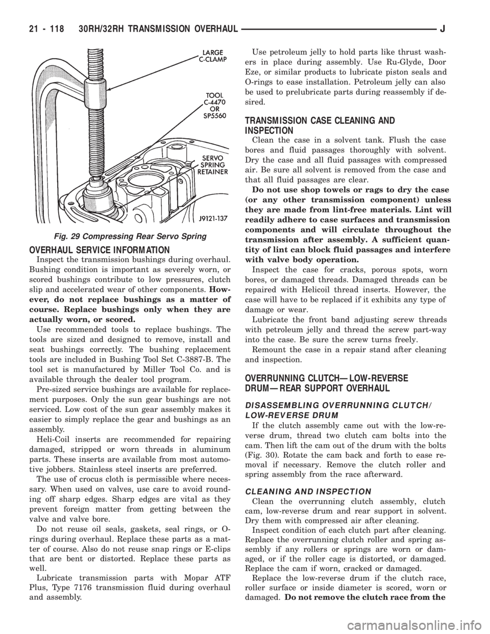
Fig. 29 Compressing Rear Servo Spring
21 - 118 30RH/32RH TRANSMISSION OVERHAULJ
Page 1280 of 1784
PRESSURE TEST ANALYSIS
If pressures in D and Reverse are higher than
specified, check for the following:
²throttle cable loose, worn, binding or out of adjust-
ment
²throttle valve, downshift plug, throttle cam, or pri-
mary regulator valve are sticking, worn or damaged
If pressures in D and Reverse are lower than spec-
ified, check for following:
²throttle cable loose, worn, binding or out of adjust-
ment
²throttle valve, downshift plug, throttle cam stick-
ing, worn or damaged
²primary regulator valve sticking, worn, or dam-
aged
²oil pump gears or housing worn or damaged
²overdrive clutch worn or damaged
If pressures are low in D range only, check for fol-
lowing:
²forward clutch worn or damaged
²fluid leakage in D range circuit (component seal
and O-rings)
If pressures are low in Reverse only, check for fol-
lowing:
²shift cable and manual valve out of adjustment
²fluid leakage in reverse circuit (component seal
and O-rings)
²direct clutch worn or damaged
²first/reverse brake worn or damaged
TORQUE CONVERTER STALL TEST
Stall testing checks the holding ability of the trans-
mission clutches and brakes and of the torque con-
verter stator overrunning clutch.
(1) Be sure transmission fluid is at normal operat-
ing temperature.
(2) Connect tachometer to engine. Position tachom-
eter so it can be viewed from drivers seat.
(3) Apply parking brakes and block wheels.
(4) Apply and hold service brakes.
(5) Shift transfer case into 2H position. On models
with NP249 transfer case, leave transfer case in 4H
position.
(6) Start engine.
WARNING: DO NOT ALLOW ANYONE TO STAND AT
THE FRONT OR REAR OF THE VEHICLE DURING
THE TEST.
(7) Shift transmission into D range.
(8) Press accelerator pedal to wide open throttle
position and note maximum engine rpm. Stall speed
should be 2100 to 2400 rpm in D range.
CAUTION: Do not maintain wide open throttle for
more than 3-4 seconds at a time.(9) Release throttle and shift transmission into
Neutral. Allow transmission fluid to cool for 15-20
seconds.
(10) Shift transmission into Reverse.
(11) Press accelerator down to wide open throttle
position and note maximum engine rpm. Stall speed
should be 2100-to-2400 rpm in Reverse.
STALL SPEED TEST ANALYSIS
If engine rpm is lower than specified in D and Re-
verse, check for the following:
²engine output/performance insufficient
²stator overrunning clutch in torque converter not
holding if engine speed was 1500 rpm or less.
If stall speed in D range is higher than specified,
check for the following:
²line pressure low
²forward clutch slipping
²No. 2 one-way clutch not holding
²overdrive one-way clutch not holding
If stall speed in Reverse was higher than specified,
check for the following:
²line pressure low
²direct clutch slipping
²first/ reverse brake slipping
²overdrive one-way clutch not holding
If stall speeds were higher than specified in both D
and Reverse, check for the following:
²low fluid level
²line pressure low
²overdrive one-way clutch not holding
TIME LAG TEST
This test checks general condition of the overdrive
clutch, forward clutch, rear clutch and first/reverse
brake. Condition is indicated by the amount of time
required for clutch/brake engagement with the en-
gine at curb idle speed. Engagement time is mea-
sured for D and Reverse positions. A stop watch is
recommended for test accuracy.
TEST PROCEDURE
(1) Check and adjust transmission fluid level if
necessary.
(2) Bring transmission to normal operating tem-
perature.
(3) Apply parking brakes and turn off air condi-
tioning unit.
(4) Shift transfer case into 2H range. On models
with NP249 transfer case, leave transfer case in 4H
range.
(5) Start engine and check curb idle speed. Adjust
speed if necessary. Curb idle must be correct to en-
sure accurate test results.
(6) Shift transmission into Neutral and set stop
watch.
(7) During following test steps, start stop watch as
soon as shift lever reaches D and Reverse ranges.
JAW-4 TRANSMISSION DIAGNOSIS 21 - 169
Page 1284 of 1784
AW-4 IN-VEHICLE SERVICE
INDEX
page page
Accumulator Pistons and Springs........... 179
Adapter Housing Seal Replacement.......... 182
Checking Fluid Level and Condition.......... 173
Manual Valve Shaft Seal Replacement....... 178
Park Interlock Cable Adjustment............ 186
Park Rod and Pawl Service................ 181
Park/Neutral Position Switch............... 173
Second Coast Brake Servo................ 181
Shift Cable Adjustment................... 186
Speed Sensor.......................... 182Speed Sensor RotorÐSpeedometer Drive Gear . 183
Throttle Position Sensor (TPS) Service....... 184
Transmission Control Module (TCM) Service . . . 173
Transmission Cooler Line Fittings........... 187
Transmission Cooler Service............... 187
Transmission Throttle Cable Adjustment....... 185
Transmission Throttle Cable Replacement..... 184
Transmission Valve Body Installation......... 177
Transmission Valve Body Removal.......... 176
Transmission Valve Body Solenoids.......... 175
CHECKING FLUID LEVEL AND CONDITION
Recommended fluid for AW-4 transmissions is Mo-
par Dexron IIE/Mercon. Mopar Dexron II may be
used if Mercon fluid is not readily available.
CHECKING FLUID LEVEL
(1) Be sure transmission fluid is at normal operat-
ing temperature. Normal operating temperature is
reached after approximately 15 miles (25 km) of op-
eration.
(2) Position vehicle on level surface. This is impor-
tant for an accurate fluid level check.
(3) Shift transmission through all gear ranges and
back to Park.
(4) Apply parking brakes.
(5) Verify that transmission is in Park.
(6) Wipe off dipstick handle to prevent dirt from
entering fill tube. Then remove dipstick and check
fluid level and condition.
(7) Correct fluid level isto FULL mark on dip-
stick when fluid is at normal operating temper-
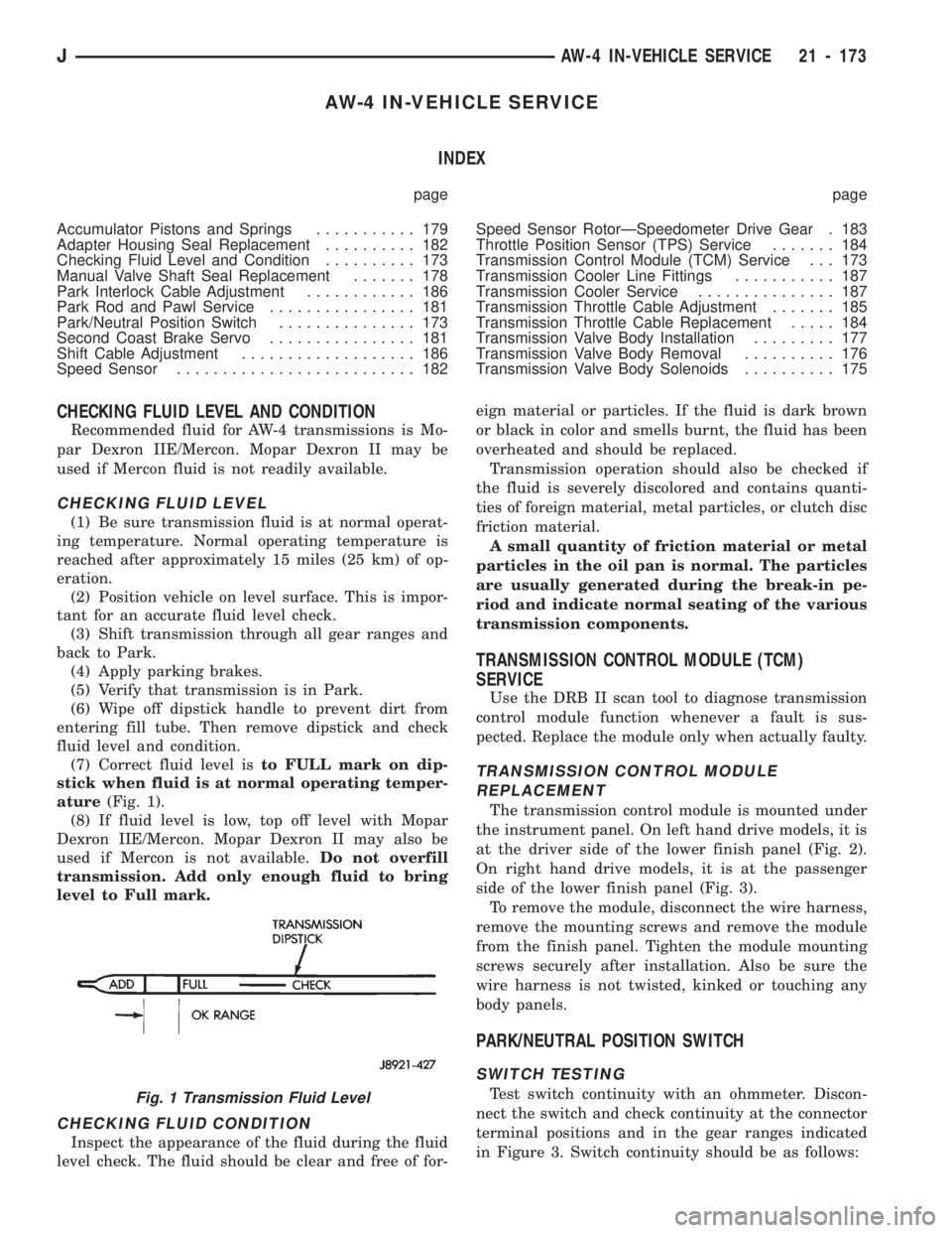
ature(Fig. 1).
(8) If fluid level is low, top off level with Mopar
Dexron IIE/Mercon. Mopar Dexron II may also be
used if Mercon is not available.Do not overfill
transmission. Add only enough fluid to bring
level to Full mark.
CHECKING FLUID CONDITION
Inspect the appearance of the fluid during the fluid
level check. The fluid should be clear and free of for-eign material or particles. If the fluid is dark brown
or black in color and smells burnt, the fluid has been
overheated and should be replaced.
Transmission operation should also be checked if
the fluid is severely discolored and contains quanti-
ties of foreign material, metal particles, or clutch disc
friction material.
A small quantity of friction material or metal
particles in the oil pan is normal. The particles
are usually generated during the break-in pe-
riod and indicate normal seating of the various
transmission components.
TRANSMISSION CONTROL MODULE (TCM)
SERVICE
Use the DRB II scan tool to diagnose transmission
control module function whenever a fault is sus-
pected. Replace the module only when actually faulty.
TRANSMISSION CONTROL MODULE
REPLACEMENT
The transmission control module is mounted under
the instrument panel. On left hand drive models, it is
at the driver side of the lower finish panel (Fig. 2).
On right hand drive models, it is at the passenger
side of the lower finish panel (Fig. 3).
To remove the module, disconnect the wire harness,
remove the mounting screws and remove the module
from the finish panel. Tighten the module mounting
screws securely after installation. Also be sure the
wire harness is not twisted, kinked or touching any
body panels.
PARK/NEUTRAL POSITION SWITCH
SWITCH TESTING
Test switch continuity with an ohmmeter. Discon-
nect the switch and check continuity at the connector
terminal positions and in the gear ranges indicated
in Figure 3. Switch continuity should be as follows:Fig. 1 Transmission Fluid Level
JAW-4 IN-VEHICLE SERVICE 21 - 173
Page 1445 of 1784
TIRE CHAINS
Tire snow chains may be used on certain models.
Refer to Owner's Manual for more information.
CLEANING OF TIRES
Steam cleaning may be used for cleaning.
DO NOT use gasoline or wire brush for cleaning.
DO NOT use mineral oil or an oil-based solvent.
PRESSURE GAUGES
High-quality, dial-type, air-pressure gauges are
recommended. After checking with the gauge, re-
place valve cap and finger tight.
TIRE INFLATION PRESSURES
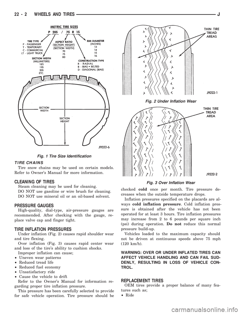
Under inflation (Fig. 2) causes rapid shoulder wear
and tire flexing.
Over inflation (Fig. 3) causes rapid center wear
and loss of the tire's ability to cushion shocks.
Improper inflation can cause;
²Uneven wear patterns
²Reduced tread life
²Reduced fuel economy
²Unsatisfactory ride
²Cause the vehicle to drift
Refer to the Owner's Manual for information re-
garding proper tire inflation pressure.
This pressure has been carefully selected to provide
for safe vehicle operation. Tire pressure should becheckedcoldonce per month. Tire pressure de-
creases when the outside temperature drops.
Inflation pressures specified on the placards are al-
wayscold inflation pressure. Cold inflation pres-
sure is obtained after the vehicle has not been
operated for at least 3 hours. Tire inflation pressures
may increase from 2 to 6 pounds per square inch
(psi) during operation.Do notreduce this normal
pressure build-up.
Vehicles loaded to the maximum capacity should
not be driven at continuous speeds above 75 mph
(120 km/h).
WARNING: OVER OR UNDER INFLATED TIRES CAN
AFFECT VEHICLE HANDLING AND CAN FAIL SUD-
DENLY, RESULTING IN LOSS OF VEHICLE CON-
TROL.
REPLACEMENT TIRES
OEM tires provide a proper balance of many fea-
tures such as;
²Ride
Fig. 1 Tire Size Identification
Fig. 2 Under Inflation Wear
Fig. 3 Over Inflation Wear
22 - 2 WHEELS AND TIRESJ
Page 1449 of 1784
WHEELS
GENERAL INFORMATION
Original equipment wheels are designed for the
specified Maximum Vehicle Capacity.
All models use steel or cast aluminum drop center
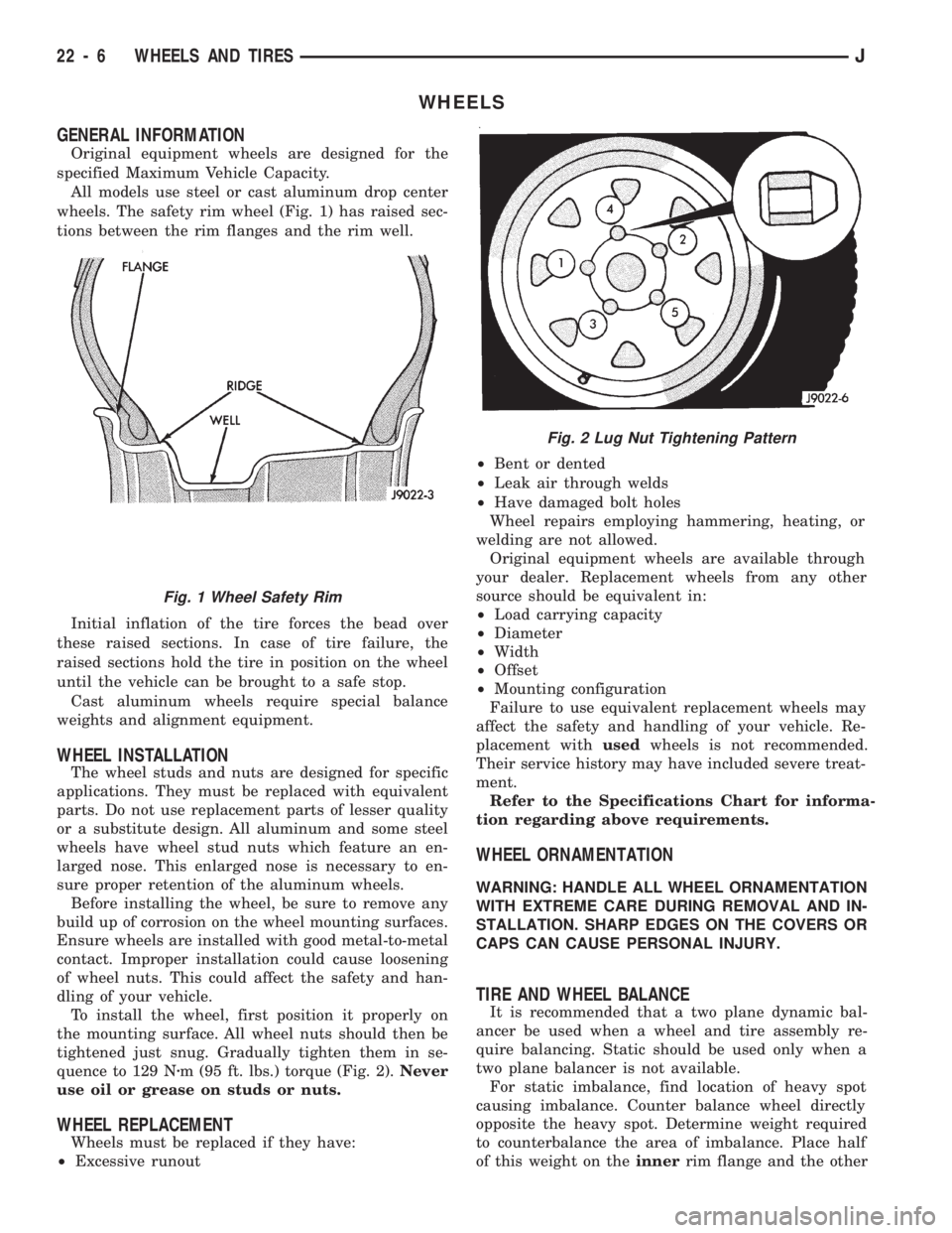
wheels. The safety rim wheel (Fig. 1) has raised sec-
tions between the rim flanges and the rim well.
Initial inflation of the tire forces the bead over
these raised sections. In case of tire failure, the
raised sections hold the tire in position on the wheel
until the vehicle can be brought to a safe stop.
Cast aluminum wheels require special balance
weights and alignment equipment.
WHEEL INSTALLATION
The wheel studs and nuts are designed for specific
applications. They must be replaced with equivalent
parts. Do not use replacement parts of lesser quality
or a substitute design. All aluminum and some steel
wheels have wheel stud nuts which feature an en-
larged nose. This enlarged nose is necessary to en-
sure proper retention of the aluminum wheels.
Before installing the wheel, be sure to remove any
build up of corrosion on the wheel mounting surfaces.
Ensure wheels are installed with good metal-to-metal
contact. Improper installation could cause loosening
of wheel nuts. This could affect the safety and han-
dling of your vehicle.
To install the wheel, first position it properly on
the mounting surface. All wheel nuts should then be
tightened just snug. Gradually tighten them in se-
quence to 129 Nzm (95 ft. lbs.) torque (Fig. 2).Never
use oil or grease on studs or nuts.
WHEEL REPLACEMENT
Wheels must be replaced if they have:
²Excessive runout²Bent or dented
²Leak air through welds
²Have damaged bolt holes
Wheel repairs employing hammering, heating, or
welding are not allowed.
Original equipment wheels are available through
your dealer. Replacement wheels from any other
source should be equivalent in:
²Load carrying capacity
²Diameter
²Width
²Offset
²Mounting configuration
Failure to use equivalent replacement wheels may
affect the safety and handling of your vehicle. Re-
placement withusedwheels is not recommended.
Their service history may have included severe treat-
ment.
Refer to the Specifications Chart for informa-
tion regarding above requirements.
WHEEL ORNAMENTATION
WARNING: HANDLE ALL WHEEL ORNAMENTATION
WITH EXTREME CARE DURING REMOVAL AND IN-
STALLATION. SHARP EDGES ON THE COVERS OR
CAPS CAN CAUSE PERSONAL INJURY.
TIRE AND WHEEL BALANCE
It is recommended that a two plane dynamic bal-
ancer be used when a wheel and tire assembly re-
quire balancing. Static should be used only when a
two plane balancer is not available.
For static imbalance, find location of heavy spot
causing imbalance. Counter balance wheel directly
opposite the heavy spot. Determine weight required
to counterbalance the area of imbalance. Place half
of this weight on theinnerrim flange and the other
Fig. 2 Lug Nut Tightening Pattern
Fig. 1 Wheel Safety Rim
22 - 6 WHEELS AND TIRESJ
Page 1668 of 1784
(2) Close all the hand valves.
(3) Connect the red charging hose to the discharge
service valve.
(4) Connect the blue charging hose to the inlet
(suction) service valve.
(5) Discharge the system. Leave the suction and
discharge service valves in the mid-position.
CAUTION: The system must be completely dis-
charged into a recovery device before evacuating. If
the system is still charged, refrigerant can enter
and damage the vacuum pump.
(6) Connect the vacuum pump hose to the vacuum
pump inlet.
(7) Open the low and high pressure control valves
on the charging station.
(8) Start the vacuum pump. Open the vacuum con-
trol valve and note the vacuum reading.
(9) Test the system for leaks as follows:
²Close the manifold hand valves.
²Stop the vacuum pump and observe the vacuum
reading.
²If the system is leak-free, vacuum will hold steady
at the level indicated when the pump was stopped. If
vacuum remains steady for 3-5 minutes, resume and
continue evacuation for a minimum of 30 minutes.
²If the system has a leak, vacuum will fall off or
rapidly drop to a 0 reading. If a leak exists, partially
charge the system. Find and repair the leak and re-
sume evacuation.
(10) Continue evacuating the system for a mini-
mum of 30 minutes after attaining the lowest vac-
uum level.
(11) Fill the station charging cylinder while the
system is evacuating.
(12) Close the vacuum control valve and stop the
vacuum pump.
(13) Observe low pressure gauge to determine if a
system leak exists. If the system is leak-free, the sys-
tem is now ready for charging.
SYSTEM CHARGE
CHARGE CAPACITY
The recommended system charge is 1.1 kg (38 oz.)
of R-12 refrigerant for XJ vehicles and 0.9 kg (32 oz.)
for YJ vehicles.
Add an additional 28 grams (1 fluid oz.) of
compressor oil to the system when a hose, re-
ceiver-drier, condenser, expansion valve or
evaporator core is replaced.
PORTABLE SERVICE STATION
(1) Fill the station charging cylinder. Refrigerant
should be observed rising in the cylinder sight glass.
(2) Slightly open the valve at the top of the cylin-
der when pressure in the charging cylinder and re-frigerant supply tank are equal. This relieves head
pressure allowing refrigerant to continue filling the
cylinder.
(3) Observe the pressure gauge at the top of the
cylinder. Rotate the plastic cover on the cylinder un-
til the pressure heading column corresponds with the
gauge pressure in-line with the sight glass.
FOR EXAMPLE:ÐThe pressure gauge at the top
of the cylinder indicates 483 kPa (70 psi). Locate the
column with the pressure heading of 483 (70) and ro-
tate the cover so the 483 (70) column aligns with the
sight glass.
(4) When refrigerant reaches the correct level in
the sight glass, close the right hand valve at cylinder
base and on the refrigerant drum.
(5) Close the valve at the top of the charging cyl-
inder.
(6) Check for bubbles in the refrigerant using the
cylinder sight glass. If bubbles appear in the refrig-
erant, tilt the charging station rearward momen-
tarily.
(7) Connect the heating element cord to the power
pack receptacle and turn the heater switch ON.
(8) Allow the refrigerant to warm for about 10
minutes while the vacuum pump is operating.
WARNING: WEAR GOGGLES TO PROTECT THE
EYES.
(9) Discharge and evacuate the system.
(10) Close the low pressure valve on the charging
station.
(11) Fully open the left hand refrigerant control
valve at the base of the cylinder and the high pres-
sure valve on the charging station.
(12) Charge the system.
(13) Close the refrigerant control valve and the
high pressure valve on the charging station.
CAUTION: DO NOT permit the liquid level to drop
below 0 on the cylinder sight glass.
(14) Close the manifold gauges after completion of
the charging operation and check the high and low
side pressures.
(15) Check system operation.
CAUTION: DO NOT check system pressures until
the high and low pressure valves on the charging
station are closed. The low pressure gauge could
be damaged if the valves are open.
(16) Close all the valves on the charging station
and close the refrigerant drum valve when all the op-
erations are completed.
(17) Back-seat the service valves by turning them
fully counterclockwise. Install the quick seal caps on
the valves afterward.
JHEATING AND AIR CONDITIONING 24 - 5
Page 1712 of 1784
WARNINGS AND CAUTIONS FOR R134A SYSTEM
WARNING: AVOID BREATHING A/C REFRIGERANT
AND LUBRICANT VAPOR OR MIST. EXPOSURE MAY
IRRITATE EYES, NOSE AND/OR THROAT. WEAR
EYE PROTECTION WHEN SERVICING THE AIR
CONDITIONING REFRIGERANT SYSTEM. SERIOUS
EYE INJURY CAN RESULT FROM EYE CONTACT
WITH REFRIGERANT. IF EYE CONTACT IS MADE,
SEEK MEDICAL ATTENTION IMMEDIATELY.
WARNING: DO NOT EXPOSE REFRIGERANT TO
OPEN FLAME. POISONOUS GAS IS CREATED
WHEN REFRIGERANT IS BURNED. AN ELEC-
TRONIC LEAK DETECTOR IS RECOMMENDED.
WARNING: IF ACCIDENTAL SYSTEM DISCHARGE
OCCURS, VENTILATE THE WORK AREA BEFORE
RESUMING SERVICE. LARGE AMOUNTS OF RE-
FRIGERANT RELEASED IN A CLOSED WORK AREA
WILL DISPLACE THE OXYGEN AND CAUSE SUFFO-
CATION.
WARNING: THE EVAPORATION RATE OF R-134A
REFRIGERANT AT AVERAGE TEMPERATURE AND
ALTITUDE IS EXTREMELY HIGH. AS A RESULT,
ANYTHING THAT COMES IN CONTACT WITH THE
REFRIGERANT WILL FREEZE. ALWAYS PROTECT
SKIN OR DELICATE OBJECTS FROM DIRECT CON-
TACT WITH REFRIGERANT.WARNING: R-134A SERVICE EQUIPMENT OR VEHI-
CLE A/C SYSTEM SHOULD NOT BE PRESSURE
TESTED OR LEAK TESTED WITH COMPRESSED
AIR. SOME MIXTURES OF AIR AND R-134A HAVE
BEEN SHOWN TO BE COMBUSTIBLE AT ELEVATED
PRESSURES. THESE MIXTURES ARE POTENTIALLY
DANGEROUS AND MAY RESULT IN FIRE OR EX-
PLOSION CAUSING INJURY OR PROPERTY DAM-
AGE.
CAUTION: Liquid refrigerant is corrosive to metal
surfaces. Follow the operating instructions supplied
with equipment being used.
CAUTION: Never add R-12 to a system designed to
use R-134a. Damage to the system will result.
CAUTION: R-12 compressor oil can not be mixed
with the R-134a compressor oil. They ARE NOT
compatible.
CAUTION: DO NOT use R-12 equipment or parts on
the R-134a system. Damage to the system will re-
sult.
SERVICE PRECAUTIONS
Never open or loosen a connection before discharg-
ing the system refrigerant.
The A/C system must always be evacuated before
charging.
DO NOT open a refrigerant system or uncap a re-
placement component unless it is as close as possible
to room temperature. This will prevent condensation
from forming inside of a component which is cooler
than the surrounding air.
Before disconnecting a component from the system,
clean the outside of the fittings thoroughly.
Immediately after disconnecting a component from
the system, seal the open fittings with a cap or plug.
Before connecting an open fitting always insall a
new seal/gasket. Coat the fitting and seal with clean
refrigerant oil before connecting.
DO NOT remove the sealing caps from a replace-
ment component until ready to install.When installing a refrigerant line avoid sharp
bends. Position the line away from the exhaust or
any sharp edges which may chafe the line.
Tighten fittings only to the specified torque. The
aluminum fittings used in the A/C system will not
tolerate over tightening.
When disconnecting a fitting use a wrench on both
halves of the fitting. This will prevent twisting of the
refrigerant lines or tubes.
Refrigerant oil will absorb moisture from the atmo-
sphere if left uncapped. DO NOT open an oil con-
tainer until ready to use and install the cap
immediately after using. Store the oil only in a clean
moisture-free container.
Keep service tools and the work area clean. Con-
tamination of A/C system through careless work hab-
its must be avoided.
JAIR CONDITIONING3
Page 1753 of 1784
FILTER REPLACEMENT, OIL.............21-100
FILTER SHIELD AND BRACKET, FUEL.......13-17
FINAL ASSEMBLY; FRONT SUSPENSION
AND AXLE...........................2-44
FINAL ASSEMBLY; REAR SUSPENSION
AND AXLES..........................3-26
FIRING ORDERÐ2.5L ENGINE, ENGINE....8D-33
FIRING ORDERÐ4.0L ENGINE, ENGINE....8D-33
FIRST GEAR (1) POSITION, HYDRAULIC
FLOW IN MANUAL...................21-94
FIRST GEAR, HYDRAULIC FLOW IN D
RANGE.............................21-87
FIRST-REVERSE BRAKE PISTON AND
TRANSMISSION CASE OVERHAUL......21-237
FIRST, SYMPTOM AND ACTIONÐSEE
PRELIMINARY CHECKS..................7-6
FIRSTÐTHIRDÐREVERSE GEAR
COMPONENTS......................21-159
FITTING CHART, CONNECTING ROD
BEARING........................9-36,9-76
FITTING CHART, MAIN BEARING.......9-43,9-83
FITTING O-RING SEAL, FLOW CONTROL
VALVE .............................19-12
FITTINGS, QUICK-CONNECT..........14-9,14-59
FITTINGS, SERVICING TRANSMISSION
COOLER LINES.....................21-106
FITTINGS, TRANSMISSION COOLER LINE . . 21-187
FIXED GLASS WATER LEAK DETECTION
AND REPAIR ..................23-83,23-189
FIXED WINDOW GLASS...........23-73,23-183
FIXED WINDOW GLASS, REAR DOOR......23-53
FLARE, FENDER......................23-144
FLARES AND LINERS, REAR
WHEELHOUSE.......................23-18
FLASHER, TURN SIGNALS AND HAZARD
WARNING...........................8A-1
FLOOR BRACKETSÐXJ VEHICLES,
SPARE TIRE/WHEEL HOLDDOWN.......23-128
FLOOR CONSOLEÐXJ VEHICLES, FULL . . . 23-125
FLOOR CONSOLES....................23-197
FLOOR MATS, CARPETS................23-129
FLOW CONTROL VALVE FITTING O-RING
SEAL..............................19-12
FLOW DURING FULL THROTTLE 3-2
DOWNSHIFT, HYDRAULIC..............21-92
FLOW DURING PART THROTTLE 3-2
DOWNSHIFT, HYDRAULIC..............21-91
FLOW IN D RANGE FIRST GEAR,
HYDRAULIC.........................21-87
FLOW IN D RANGE SECOND GEAR,
HYDRAULIC.........................21-88
FLOW IN D RANGE THIRD GEAR,
HYDRAULIC.........................21-89
FLOW IN MANUAL FIRST GEAR
(1) POSITION, HYDRAULIC.............21-94
FLOW IN MANUAL SECOND (2) RANGE,
HYDRAULIC.........................21-93
FLOW IN PARK AND NEUTRAL,
HYDRAULIC.........................21-86
FLOW IN REVERSE, HYDRAULIC..........21-95
FLOW IN THIRD GEAR (CONVERTER
CLUTCH ENGAGED), HYDRAULIC........21-90
FLOW TESTING, TRANSMISSION
COOLER...........................21-106
FLUID AND LEVELÐBRAKELINES
AND HOSES, BRAKE BLEEDINGÐ
BRAKE..............................5-13
FLUID CAPACITIES.......................0-4
FLUID, CLUTCH LINKAGE
..................6-1
FLUID CONTAMINATION, BRAKE
...........5-13
FLUID, IMPORTANCE OF CLEAN BRAKE
.....5-48
FLUID LEVEL AND CONDITION
...........21-69
FLUID LEVEL AND CONDITION,
CHECKING
....................21-96,21-173
FLUID LEVEL, BRAKE
....................5-13
FLUID LEVEL, CLUTCH
...................6-14
FLUID LEVEL, CORRECT
.................5-48
FLUID, RECOMMENDED
............21-66,21-96
FLUID, RECOMMENDED BRAKE; BRAKES
....5-13,
5-48
FLUID TUBE RETAINER CLIP, FUEL AND
BRAKE; BODY COMPONENTSÐXJ
VEHICLES
..........................23-86
FLUID TUBE RETAINER CLIP, FUEL
AND BRAKE; FRAME AND BUMPERS
.....13-16FLUID/LUBRICANTS/CLEANING
SOLVENTS, BRAKE.....................5-1
FLUSHING, COOLING SYSTEM CLEANING/
REVERSE............................7-17
FLUSHING, TRANSMISSION COOLER
REVERSE..........................21-105
FLYWHEEL SERVICE.....................6-15
FOG LAMP BEAM ADJUSTMENT..........8L-12
FOG LAMP BULB/ELEMENT
REPLACEMENT......................8L-13
FOG LAMP REPLACEMENT..............8L-15
FOG LAMP SERVICE INFORMATION........8L-12
FOG LAMP SWITCH REPLACEMENT.......8L-14
FOG LAMP TROUBLE DIAGNOSIS.........8L-12
FOG LAMPÐYJ RENEGADE VEHICLES....23-150
FORM-IN-PLACE GASKETS.................9-1
FORMULAS AND EQUIVALENT VALUES,
CONVERSION.....................INTRO.-8
FORWARD CLUTCH OVERHAUL..........21-223
FOURTH GEAR OVERDRIVE COMPONENTS . . 21-158
FRAME ALIGNMENT....................13-10
FRAME, BUCKET SEATBACK COVER......23-100
FRAME CROSSMEMBER COVER..........13-14
FRAME INSPECTION/MEASUREMENTS.....13-10
FRAME REPAIR SERVICE................13-13
FRAME WEATHERSTRIP SEAL,
WINDSHIELD.......................23-185
FRAME, WINDSHIELD.................23-184
FRAME, YJ............................13-8
FRESH AIR DOOR VACUUM MOTOR.......24-41
FRESH AIR INTAKE DUCT...............24-41
FRESH AIR VENTILATION................24-39
FRONT AND REAR AXLES................0-26
FRONT AXLE, MODEL 30.................2-46
FRONT BAND ADJUSTMENT.............21-99
FRONT BUCKET SEATS..................23-97
FRONT BUMPER...................13-3,13-14
FRONT CABLE REPLACEMENT (YJ),
PARKING BRAKE......................5-62
FRONT CARPET/MATÐXJ VEHICLES......23-129
FRONT CLUTCH OVERHAUL.............21-125
FRONT DOOR SPACER BLOCKSÐTWO-
DOOR VEHICLES.....................23-60
FRONT DOOR VENT WINDOW............23-50
FRONT DOOR WINDOW GLASS...........23-49
FRONT DOOR WINDOW GLASS
REGULATOR........................23-48
FRONT DRIVE AXLE......................2-3
FRONT FASCIA AND SKID PLATEÐYJ
RENEGADE VEHICLES................23-148
FRONT FENDER.......................23-14
FRONT FENDER EXTENSION PANELÐYJ
RENEGADE VEHICLES................23-149
FRONT INNER SCUFF PLATE/COWL SIDE
TRIM PANELÐXJ VEHICLES...........23-114
FRONT PARK/TURN SIGNAL LAMP BULB
REPLACEMENT.......................8L-8
FRONT PLANETARY GEAR OVERHAUL.....21-228
FRONT SERVO AND BAND OVERHAUL....21-136
FRONT SHOULDER BELT/BUCKLEÐXJ
VEHICLES.........................23-119
FRONT SHOULDER BELTS..............23-196
FRONT SKID PLATE....................23-84
FRONT SUPPORT CUSHION, ENGINE.......13-15
FRONT SUSPENSION.....................2-1
FRONT SUSPENSION COMPONENTS, XJ.....2-47
FRONT SUSPENSION COMPONENTS, YJ.....2-47
FRONT SUSPENSION, XJ.................2-10
FRONT SUSPENSION, YJ.................2-13
FRONT TOW HOOKS
....................13-5
FRONT WHEEL ALIGNMENT
................2-5
FRONT WHEEL BEARINGS
................0-31
FRONT WHEEL SENSOR INSTALLATION
.....5-49
FRONT WHEEL SENSOR REMOVAL
.........5-49
FRONT WIPER ARM AND PIVOT
ASSEMBLY REPLACEMENT
..............8K-9
FRONT WIPER ARM REPLACEMENT
........8K-8
FRONT WIPER BLADE REPLACEMENT
......8K-8
FRONT WIPER MOTOR
.................8K-10
FRONT WIPERS/WASHERS
...............8K-1
FRONT WIPERS/WASHERS GENERAL
INFORMATION
........................8K-8
FUEL AND BRAKE FLUID TUBE RETAINER
CLIP; BODY COMPONENTSÐXJ
VEHICLES
..........................23-86FUEL AND BRAKE FLUID TUBE
RETAINER CLIP; FRAME AND BUMPERS . . . 13-16
FUEL DELIVERY SYSTEM.................14-2
FUEL FILLER DOOR BUMPERS...........23-31
FUEL FILLER HOSE SPLASH SHIELDÐXJ
VEHICLES..........................23-86
FUEL FILLER NOZZLE/TUBE..............23-30
FUEL FILLER PROTECTOR/NOZZLE.......23-158
FUEL FILTER......................14-8,14-55
FUEL FILTER BRACKET..................23-86
FUEL FILTER SHIELD AND BRACKET.......13-17
FUEL GAUGE..........................8E-2
FUEL GAUGE INOPERATIVE...............8E-3
FUEL GAUGE SENDING UNIT.............14-15
FUEL INJECTION (MFI)ÐCOMPONENT
DESCRIPTION/SYSTEM OPERATION,
MULTI-PORT........................14-17
FUEL INJECTION (MFI)ÐCOMPONENT
REMOVAL/INSTALLATION, MULTI-PORT . . . 14-54
FUEL INJECTION (MFI)ÐGENERAL
DIAGNOSIS, MULTI-PORT..............14-32
FUEL INJECTOR.......................14-55
FUEL INJECTORSÐPCM OUTPUT.........14-25
FUEL PRESSURE LEAK DOWN TEST........14-7
FUEL PRESSURE REGULATOR............14-30
FUEL PRESSURE RELEASE PROCEDURE.....14-5
FUEL PUMP CAPACITY TEST..............14-7
FUEL PUMP ELECTRICAL CONTROL........14-5
FUEL PUMP MODULE..............14-2,14-56
FUEL PUMP RELAY....................14-56
FUEL PUMP RELAYÐPCM OUTPUT.......14-25
FUEL PUMP RELAY TESTING.............14-44
FUEL RAIL...........................14-30
FUEL RAIL ASSEMBLY..................14-56
FUEL REQUIREMENTS....................0-2
FUEL SYSTEM........................14-62
FUEL SYSTEM PRESSURE RELEASE
PROCEDURE........................14-56
FUEL SYSTEM PRESSURE TEST......14-5,14-48
FUEL TANK...........................14-12
FUEL TANK CAPACITIES............14-12,14-62
FUEL TANK FILLER TUBE CAP;
EMISSION CONTROL SYSTEMS......25-4,25-9
FUEL TANK FILLER TUBE CAP; FUEL
SYSTEM............................14-12
FUEL TANK FILLER TUBE, NO-LEAD.......14-12
FUEL TANK PRESSURE RELIEF/
ROLLOVER VALVE...............14-15,14-56
FUEL TANK SKID PLATE; BODY
COMPONENTSÐXJ VEHICLES..........23-84
FUEL TANK SKID PLATE; FRAME AND
BUMPERS..........................13-16
FUEL TANK SUPPORT STRAP............23-86
FUEL TANKS.....................14-12,14-56
FUEL TUBES/LINES/HOSES AND CLAMPS . . . 14-9,
14-56
FUEL USAGE STATEMENT................14-1
FUEL USAGE STATEMENTÐGAS
ENGINES............................0-17
FUEL WARNING INOPERATIVE, LOW........8E-4
FUEL WARNING LAMP, LOW..............8E-2
FULL FLOOR CONSOLEÐXJ VEHICLES....23-125
FULL-METAL DOOR ASSIST HANDLE.....23-175
FULL-METAL DOOR HINGES............23-179
FULL-METAL DOOR KEY LOCK
CYLINDER.........................23-178
FULL-METAL DOOR LATCH.............23-179
FULL-METAL DOOR LATCH EXTERNAL
RELEASE HANDLE...................23-178
FULL-METAL DOOR LATCH INSIDE
RELEASE AND LOCK HANDLE..........23-175
FULL-METAL DOOR SERVICE............23-181
FULL-METAL DOOR TRIM PANEL........23-175
FULL-METAL DOOR VENT WINDOW
GLASS............................23-177
FULL-METAL DOOR WATERDAM.........23-176
FULL-METAL DOOR WEATHERSTRIP
SEALS............................23-180
FULL-METAL DOOR WINDOW GLASS.....23-178
FULL-METAL DOOR WINDOW GLASS
REGULATOR
.......................23-177
FULL-METAL DOOR WINDOW GLASS
REGULATOR HANDLE
................23-175
FUNCTION TROUBLE DIAGNOSISÐXJ
VEHICLES, HEADLAMP DELAY
..........8L-16
FUSE CHARTS AND RELAY BANKS
.........8W-8
JINDEX9
Description Group-Page Description Group-Page Description Group-Page